TROUBLE DIAGNOSIS
ATC-59
C
D
E
F
G
H
I
K
L
MA
B
AT C
Revision: 2006 November2007 350Z
9. CHECK MODE DOOR MOTOR AND AIR MIX DOOR MOTOR OPERATION
1. Turn ignition switch OFF.
2. Disconnect intake door motor connector.
3. Reconnect air mix door motor connector.
4. Turn ignition switch ON.
5. Confirm operation of mode door motor and air mix door motor.
OK or NG
OK >> Mode door motor and air mix door motor operate normally.
�Replace intake door motor.
NG >> Mode door motor and air mix door motor does not operate normally.
�Replace unified meter and A/C amp.
ATC-70
TROUBLE DIAGNOSIS
Revision: 2006 November2007 350Z
SYSTEM DESCRIPTION
Component Parts
Fan speed control system components are:
�Unified meter and A/C amp.
�A/C LAN system (PBR built-in mode door motor, air mix door motor and intake door motor)
�In-vehicle sensor
�Ambient sensor
�Sunload sensor
�Intake sensor
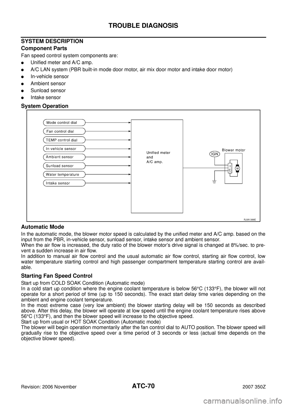
System Operation
Automatic Mode
In the automatic mode, the blower motor speed is calculated by the unified meter and A/C amp. based on the
input from the PBR, in-vehicle sensor, sunload sensor, intake sensor and ambient sensor.
When the air flow is increased, the duty ratio of the blower motor’s drive signal is changed at 8%/sec. to pre-
vent a sudden increase in air flow.
In addition to manual air flow control and the usual automatic air flow control, starting air flow control, low
water temperature starting control and high passenger compartment temperature starting control are avail-
able.
Starting Fan Speed Control
Start up from COLD SOAK Condition (Automatic mode)
In a cold start up condition where the engine coolant temperature is below 56°C (133°F), the blower will not
operate for a short period of time (up to 150 seconds). The exact start delay time varies depending on the
ambient and engine coolant temperature.
In the most extreme case (very low ambient) the blower starting delay will be 150 seconds as described
above. After this delay, the blower will operate at low speed until the engine coolant temperature rises above
56°C (133°F), and then the blower speed will increase to the objective speed.
Start up from usual or HOT SOAK Condition (Automatic mode)
The blower will begin operation momentarily after the fan control dial to AUTO position. The blower speed will
gradually rise to the objective speed over a time period of 3 seconds or less (actual time depends on the
objective blower speed).
RJIA1388E
ATC-140
REFRIGERANT LINES
Revision: 2006 November2007 350Z
CHECKING PROCEDURE
To prevent inaccurate or false readings, make sure there is no refrigerant vapor, shop chemicals, or cigarette
smoke in the vicinity of the vehicle. Perform the leak test in calm area (low air/wind movement) so that the
leaking refrigerant is not dispersed.
1. Stop the engine.
2. Connect a suitable A/C manifold gauge set (SST:J-39183) to the A/C service valves.
3. Check if the A/C refrigerant pressure is at least 345 kPa (3.52 kg/cm
2 , 50 psi) above 16°C (61°F). If less
than specification, recover/evacuate and recharge the system with the specified amount of refrigerant.
NOTE:
At temperatures below 16°C (61°F), leaks may not be detected since the system may not reach 345 kPa
(3.52 kg/cm
2 , 50 psi).
4. Perform the leak test from the high-pressure side (compressor discharge a to evaporator inlet g) to the
low-pressure side (evaporator drain hose h to shaft seal l). Refer to ATC-125, "
Components" . Perform a
leak check for the following areas carefully. Clean the component to be checked and move the leak
detected probe completely around the connection/component.
Compressor
Check the fitting of high- and low-pressure flexible hoses, relief valve and shaft seal.
Condenser
Check the fitting of high-pressure flexible hose and pipe.
Liquid tank
Check the fitting of refrigerant connection.
Service valves
Check all around the service valves. Ensure service valve caps are secured on the service valves (to pre-
vent leaks).
NOTE:
After removing A/C manifold gauge set from service valves, wipe any residue from valves to prevent any
false readings by leak detector.
Cooling unit (Evaporator)
With engine OFF, turn blower fan on “High” for at least 15 seconds to dissipate any refrigerant trace in the
cooling unit. Wait a minimum of 10 minutes accumulation time (refer to the manufacturer’s recommended
procedure for actual wait time) before inserting the leak detector probe into the drain hose.
Keep the probe inserted for at least 10 seconds. Use caution not to contaminate the probe tip with water
or dirt that may be in the drain hose.
5. If a leak detector detects a leak, verify at least once by blowing compressed air into area of suspected
leak, then repeat check as outlined above.
6. Do not stop when one leak is found. Continue to check for additional leaks at all system components.
If no leaks are found, perform steps 7 - 10.
7. Start the engine.
8. Set the A/C control as follows;
a. A/C switch: ON
b. MODE door position: VENT (Ventilation)
c. Intake door position: Recirculation
d. Temperature setting: Max. cold
e. Fan speed: High
9. Run engine at 1,500 rpm for at least 2 minutes.
10. Stop the engine and perform leak check again following steps 4
through 6 above.
Refrigerant leaks should be checked immediately after stopping
the engine. Begin with the leak detector at the compressor. The
pressure on the high-pressure side will gradually drop after
refrigerant circulation stops and pressure on the low-pressure
side will gradually rise, as shown in the graph. Some leaks are
more easily detected when pressure is high.
SHA839E