Page 398 of 473

397 Practical hints
Replacing bulbs
�Replacing bulbs
Bulbs
Safe vehicle operation depends on proper
exterior lighting and signaling. It is there-
fore essential that all bulbs and lamp as-
semblies are in good working order at all
times.
Correct headlamp adjustment is extremely
important. Have headlamps checked and
readjusted at regular intervals and when a
bulb has been replaced. See an authorized
Mercedes-Benz Center for headlamp ad-
justment.
Warning!
G
Bulbs and bulb sockets can be very hot. Al-
low the lamp to cool down before changing
a bulb.
Keep bulbs out of reach of children.
Halogen lamps contain pressurized gas. A
bulb can explode if you:�
touch or move it when hot
�
drop the bulb
�
scratch the bulb
Wear eye and hand protection.
Because of high voltage in Xenon lamps, it is
dangerous to replace the bulb or repair the
lamp and its components. We recommend
that you have such work done by a qualified
technician.
i
If the headlamps or front fog lamps are
fogged up on the inside as a result of high humid-
ity, driving the vehicle a distance with the lights
on should clear up the fogging.
i
Auxiliary bulbs will be brought into use when
the following lamps malfunction:
�
Turn signal lamps
�
Brake lamps
�
Parking lamps
�
Tail lamps
Observe the messages in the multifunction dis-
play (�page 347).
Page 401 of 473

400 Practical hintsReplacing bulbs4High beam bulbs
5Locking mechanism
6Parking and standing lampsFront turn signal bulb
�
Turn bulb socket 1 counterclockwise
and pull it out.
�
Push the bulb into socket 1, turn
socket 1 counterclockwise and re-
move it.
�
Insert the new bulb in socket 1, push
and turn bulb socket 1 clockwise.
�
Reinsert bulb socket 1 in lamp and
turn bulb socket 1 clockwise.High beam/ high beam flasher bulbs
�
Press ends of headlamp cover tab to-
gether and remove high beam head-
lamp cover 2.
�
Pull the electrical connector off.
�
Turn locking mechanism 5 counter-
clockwise and take out the bulb.
�
Insert the new bulb so that the base lo-
cates in the recess on the holder.
�
Turn locking mechanism 5 clockwise.
�
Plug the connector onto the bulb.
�
Align high beam headlamp cover 2
and click it into place.
Warning!
G
Do not remove the cover for the Xenon or
Bi-Xenon* headlamp. Because of high volt-
age in Xenon and Bi-Xenon* lamps, it is dan-
gerous to replace the bulb or repair the lamp
and its components. We recommend that
you have such work done by a qualified
technician.
Page 404 of 473

403 Practical hints
Replacing wiper blades
�Replacing wiper blades
Placing wiper arms in vertical positionWiper blades in vertical positionVehicles with SmartKey�
Turn SmartKey to starter switch
position1 (
�page 39).
�
Turn combination switch to wiper
settingII (
�page 57).
�
With wiper arms in the vertical position,
turn SmartKey in starter switch to
position0.
�
Remove SmartKey from starter switch.
Warning!
G
For safety reasons, switch off wipers and re-
move SmartKey from starter switch (vehi-
cles with KEYLESS-GO*: Make sure the
vehicle’s on-board electronics have
status0) before replacing a wiper blade.
Otherwise the wiper motor could suddenly
turn on and cause injury. Warning!
G
Wiper blades are components that are sub-
ject to wear and tear. Change the wiper
blades twice a year, preferably in the spring
and fall. Otherwise the windows will not be
properly wiped. As a result, you may not be
able to observe surrounding traffic condi-
tions and could cause an accident.
!
To avoid damage to the hood:
�
The wiper arms should only be folded for-
ward when in the vertical position.
�
Never open the hood when the wiper arm is
folded forward.
!
Never open the hood when the wiper arms
are folded forward.
Hold on to the wiper when folding the wiper arm
back. If released, the force of the impact from
the tensioning spring could crack the windshield.
Do not allow the wiper arms to contact the wind-
shield glass without a wiper blade inserted.
Make sure the wiper blades are properly in-
stalled. Improperly installed wiper blades may
cause windshield damage.
For your convenience, we recommend that you
have this work carried out by an authorized
Mercedes-Benz Center.
Page 406 of 473

405 Practical hints
Flat tire
�Flat tire
Preparing the vehicle�
Park the vehicle in a safe distance from
moving traffic on a hard, flat surface
when possible.
�
Turn on the hazard warning flashers.
�
Turn the steering wheel so that the
front wheels are in a straight ahead po-
sition.
�
Set the parking brake.
�
Move the gear selector lever to P.
Vehicles with SmartKey:
�
Turn off the engine (
�page 62).
�
Remove the SmartKey from the starter
switch.
Vehicles with KEYLESS-GO*:�
Turn off the engine by pressing the
KEYLESS-GO* button on the gear
selector lever once (
�page 62).
�
Open the driver’s door (this puts
the starter switch in position 0,
same as with the SmartKey re-
moved from the starter switch). The
driver’s door then can be closed
again.
�
Have any passenger exit the vehicle at
a safe distance from the roadway.
Mounting the spare wheel
i
Open door only when conditions are safe to
do so.
Warning!
G
The dimensions of the spare wheel are dif-
ferent from those of the road wheels. As a
result, the vehicle handling characteristics
change when driving with a mounted spare
wheel. Adapt your driving style accordingly.
The spare wheel is for temporary use only.
When driving with spare wheel mounted, en-
sure proper tire inflation pressure and do
not exceed vehicle speed of 50 mph
(80 km/h).
Drive to the nearest Mercedes-Benz Center
as soon as possible to have the spare wheel
replaced with a regular road wheel.
Never operate the vehicle with more than
one spare wheel mounted.
Do not switch off the ESP
® when a spare
wheel is mounted.
Page 408 of 473
.
�
On wheel to be changed, loosen but do
not yet remove the")
407 Practical hints
Flat tire
�
Take the vehicle tool kit and the jack
out of the storage compartment under
the trunk floor (
�page 388).
�
On wheel to be changed, loosen but do
not yet remove the wheel bolts (ap-
proximately one full turn with wrench).
The jack support tubes are located behind
the front wheel housings and in front of the
rear wheel housings.
Warning!
G
The jack is designed exclusively for jacking
up the vehicle at the jack tubes built into
both sides of the vehicle. To help avoid per-
sonal injury, use the jack only to lift the ve-
hicle during a wheel change. Never get
beneath the vehicle while it is supported by
the jack. Keep hands and feet away from the
area under the lifted vehicle. Always firmly
set parking brake and block wheels before
raising vehicle with jack.
Do not disengage parking brake while the
vehicle is raised. Be certain that the jack is
always vertical (plumb line) when in use, es-
pecially on hills. Always try to use the jack
on level surface. Be sure that the jack arm is
fully inserted in the jack tube. Always lower
the vehicle onto sufficient capacity jack-
stands before working under the vehicle.
Warning!
G
When turning the wheel wrench to loosen
the wheel bolts, make sure you position
hands on the wrench in such a way that you
avoid injury to yourself, such as scraping
your hands against the wheel. Make sure
turning the wheel wrench will not scratch or
damage the wheel rim.
��
Page 409 of 473
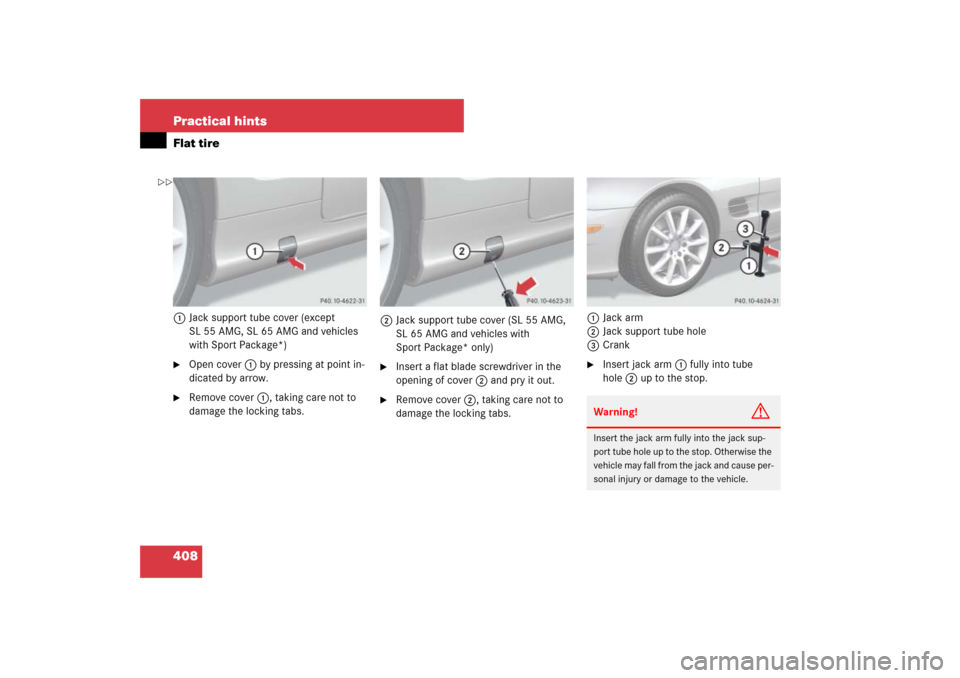
408 Practical hintsFlat tire1Jack support tube cover (except
SL 55 AMG, SL 65 AMG and vehicles
with Sport Package*)�
Open cover1 by pressing at point in-
dicated by arrow.
�
Remove cover1, taking care not to
damage the locking tabs.2Jack support tube cover (SL 55 AMG,
SL 65 AMG and vehicles with
Sport Package* only)
�
Insert a flat blade screwdriver in the
opening of cover2 and pry it out.
�
Remove cover2, taking care not to
damage the locking tabs.1Jack arm
2Jack support tube hole
3Crank
�
Insert jack arm1 fully into tube
hole2 up to the stop.Warning!
G
Insert the jack arm fully into the jack sup-
port tube hole up to the stop. Otherwise the
vehicle may fall from the jack and cause per-
sonal injury or damage to the vehicle.
��
Page 410 of 473
409 Practical hints
Flat tire
�
Keeping jack in this position, turn
crank3 clockwise until the jack base
meets the ground. Make sure the jack
is vertical (plumb line).
�
Continue to turn the crank until the tire
is a maximum of 1.2 in (3 cm) from the
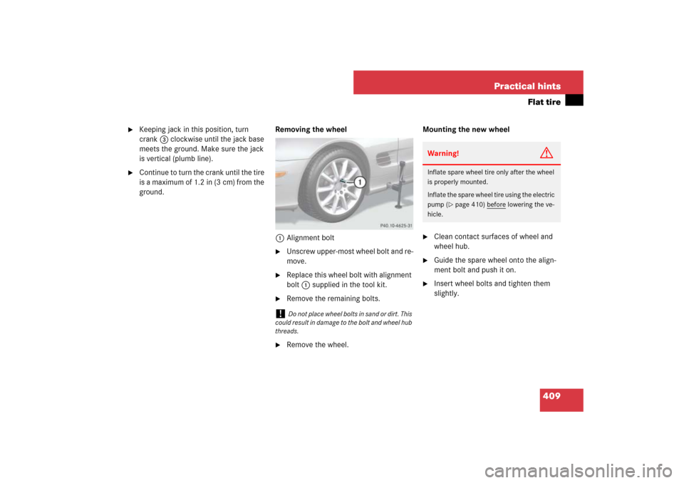
ground.Removing the wheel
1Alignment bolt
�
Unscrew upper-most wheel bolt and re-
move.
�
Replace this wheel bolt with alignment
bolt1 supplied in the tool kit.
�
Remove the remaining bolts.
�
Remove the wheel.Mounting the new wheel
�
Clean contact surfaces of wheel and
wheel hub.
�
Guide the spare wheel onto the align-
ment bolt and push it on.
�
Insert wheel bolts and tighten them
slightly.
!
Do not place wheel bolts in sand or dirt. This
could result in damage to the bolt and wheel hub
threads.
Warning!
G
Inflate spare wheel tire only after the wheel
is properly mounted.
Inflate the spare wheel tire using the electric
pump (
�page 410) before
lowering the ve-
hicle.
Page 411 of 473

�
Take the electric air pump out of the
trunk (
�")
410 Practical hintsFlat tire
�
Unscrew the alignment bolt, install last
wheel bolt and tighten slightly.
Inflating the spare tire (collapsible tire)
�
Take the electric air pump out of the
trunk (
�page 388).1Flap
2Air pump switch
3Electrical plug
4Air hose with pressure gauge and vent
screw
5Union nut
�
Open flap 1 on air pump.
�
Pull out electrical plug 3 and air hose
with the pressure gauge 4.
�
Remove the valve cap from the tire
valve.
�
Screw union nut 5 onto the tire valve.
�
Insert electrical plug 3 into vehicle ci-
gar lighter socket.
Warning!
G
Always replace wheel bolts that are dam-
aged or rusted.
Never apply oil or grease to wheel bolts.
Damaged wheel hub threads should be re-
paired immediately. Do not continue to drive
under these circumstances! Contact an au-
thorized Mercedes-Benz Center or call
Roadside Assistance.
Incorrect wheel bolts or improperly tight-
ened wheel bolts can cause the wheel to
come off. This could cause an accident. Be
sure to use the correct wheel bolts.
Warning!
G
Only use genuine equipment
Mercedes-Benz wheel bolts. They are identi-
fied by the Mercedes star. Other wheel bolts
may come loose.
Do not tighten the wheel bolts when the ve-
hicle is raised. Otherwise the vehicle could
fall off the jack.!
Do not lower the vehicle before inflating the
spare wheel tire. Otherwise the rim may be dam-
aged.
Warning!
G
Observe instructions on air pump label.