Page 243 of 473
242 Controls in detailUseful features1Retracted hardtop
2Luggage cover
3Load assist button
Hardtop 1 can only be raised or lowered
when�
luggage cover 2 is closed
�
the trunk lid is completely openedRaising the hardtop
�
Press button3.
Hardtop 1 rises a short distance.
Button3 comes on brightly. You can
now open luggage cover 2.
Lowering the hardtop
�
Close luggage cover 2.
�
Press button3.
Hardtop 1 lowers. Button3 is dimly
lit.
Power outlet
A power outlet is located on the right side
of the trunk.�
Switch on the ignition (
�page 39).
�
Flip up cover and insert electrical plug
(cigar lighter type).
!
Only close the trunk if the hardtop is com-
pletely lowered. Otherwise you could damage
the hardtop.
If you begin to close the trunk lid before the hard-
top is completely lowered, button3 will flash
and a warning will sound.
i
The power outlet can be used to accommo-
date electrical consumers (e.g. air pump,
auxiliary lamps) up to a maximum of 180 W.
Page 390 of 473
389 Practical hints
Where will I find ...?
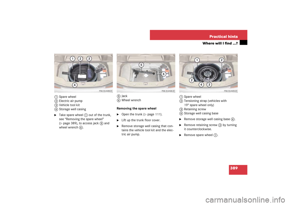
1Spare wheel
2Electric air pump
3Vehicle tool kit
4Storage well casing�
Take spare wheel 1 out of the trunk,
see “Removing the spare wheel”
(�page 389), to access jack 5 and
wheel wrench 6.5Jack
6Wheel wrench
Removing the spare wheel
�
Open the trunk (
�page 111).
�
Lift up the trunk floor cover.
�
Remove storage well casing that con-
tains the vehicle tool kit and the elec-
tric air pump.1Spare wheel
2Tensioning strap (vehicles with
19" spare wheel only)
3Retaining screw
4Storage well casing base
�
Remove storage well casing base 4.
�
Remove retaining screw 3 by turning
it counterclockwise.
�
Remove spare wheel 1.
Page 411 of 473

�
Take the electric air pump out of the
trunk (
�")
410 Practical hintsFlat tire
�
Unscrew the alignment bolt, install last
wheel bolt and tighten slightly.
Inflating the spare tire (collapsible tire)
�
Take the electric air pump out of the
trunk (
�page 388).1Flap
2Air pump switch
3Electrical plug
4Air hose with pressure gauge and vent
screw
5Union nut
�
Open flap 1 on air pump.
�
Pull out electrical plug 3 and air hose
with the pressure gauge 4.
�
Remove the valve cap from the tire
valve.
�
Screw union nut 5 onto the tire valve.
�
Insert electrical plug 3 into vehicle ci-
gar lighter socket.
Warning!
G
Always replace wheel bolts that are dam-
aged or rusted.
Never apply oil or grease to wheel bolts.
Damaged wheel hub threads should be re-
paired immediately. Do not continue to drive
under these circumstances! Contact an au-
thorized Mercedes-Benz Center or call
Roadside Assistance.
Incorrect wheel bolts or improperly tight-
ened wheel bolts can cause the wheel to
come off. This could cause an accident. Be
sure to use the correct wheel bolts.
Warning!
G
Only use genuine equipment
Mercedes-Benz wheel bolts. They are identi-
fied by the Mercedes star. Other wheel bolts
may come loose.
Do not tighten the wheel bolts when the ve-
hicle is raised. Otherwise the vehicle could
fall off the jack.!
Do not lower the vehicle before inflating the
spare wheel tire. Otherwise the rim may be dam-
aged.
Warning!
G
Observe instructions on air pump label.
Page 412 of 473

411 Practical hints
Flat tire
�
Turn the SmartKey in the starter switch
to position1.
or
�
Press the KEYLESS-GO* start/stop
button on the gear selector lever once
without depressing the brake pedal.
�
PressI on the electric air pump
switch2.
The electric air pump should now
switch on and inflate the tire.
�
Inflate the spare tire:�
SL 550 to 36 psi (2.5 bar)
�
SL 600, SL 55 AMG, SL 55 AMG
(Performance Package*), and
SL 65 AMG to 51 psi (3.5 bar)
This takes about 5 minutes.
Air hose4 and union nut5 can be-
come hot during inflation. Exercise
proper caution to avoid burning your-
self when using the equipment.
�
Press0 on the electric air pump
switch2.
�
Turn the SmartKey in the starter switch
to position0.
or
�
Press KEYLESS-GO* start/stop button
on the gear selector lever twice without
depressing the brake pedal.
The electric air pump should now be
switched off.
�
If the spare tire inflation pressure is
above the recommended tire inflation
pressure for the respective collapsible
tire (
�page 440), release excess spare
tire inflation pressure using the vent
screw.
�
Detach the electric air pump.
�
Stow the electrical plug and the air
hose behind the flap and place the air
pump back in the trunk.
!
Compare the recommended tire inflation
pressure for your vehicle with the tire inflation
pressure on the yellow label located on the spare
wheel rim.
If the tire inflation pressure on the yellow label
on the spare wheel rim differs from the values
given in this Operator’s Manual, inflate the tire to
the recommended tire inflation pressure given
on the yellow label on the spare wheel rim.
!
Do not operate the electric air pump longer
than 8 minutes without interruption. Otherwise it
may overheat.
You may operate the air pump again after it has
cooled off.
Warning!
G
Follow recommend inflation pressures.
Do not overinflate tires. Overinflating tires
can result in sudden deflation (blowout) be-
cause they are more likely to become punc-
tured or damaged by road debris, potholes,
etc.
Do not underinflate tires. Underinflated tires
wear unevenly, adversely affect handling
and fuel economy, and are more likely to fail
from being overheated.
��
Page 458 of 473

457 Index
Driving systems 209
ABC 225
Cruise control 209
Distronic* 213
Parktronic* 228
DTR see Distronic*
E
Easy-entry/exit feature 46, 162
Messages in the multifunction
display 375
Electric air pump 389, 410
Electrical outlet see Power outlet
Electro-hydraulic brake system 87, 92
Activation 93
Deactivation 94
Driving hints 95
Messages in the multifunction
display 367, 368
Self-check 94
Warning lamp 92
Electronic Stability Program see ESP
®
Emergency calls
Tele Aid 244, 245
Emergency engine shut-down 426
Emergency operation (Limp-Home
Mode) 179Emergency operations
Automatic transmission (Limp-Home
Mode) 179
Glove box, Unlocking 392
Load assist, Lowering 394
Locking/unlocking the vehicle 391,
393
Remote door unlock, Tele Aid 250
Trunk lid, Releasing from the
inside 117
Trunk lid, Unlocking 392
Emergency Tensioning Device see ETD
Emission control 269
Information label 431
System warranties 10
Vacuum line routing diagram
label 431
Engine
Block heater (Canada only) 317
Break-in recommendations 258
Cleaning 324
Compartment 274
Malfunction indicator lamp 29, 336
Number 431
Poly-V-belt layout 432
Starting 52Tachometer 29
Technical data 433
Turning off 62
Engine coolant see Coolant
Engine oil 275, 446
Adding 278, 444
Additives 446
Checking level, With control
system 276
Checking level, With oil dipstick 278
Consumption 275
Filler neck 278, 279
Messages in the multifunction
display 277, 375
Oil dipstick 278
ESP
®
87, 89
Switch 32
Switching off 91
Switching on 92
Synchronizing 355
Warning lamp 27, 332
ETD 81
Safety guidelines 70
Warning and indictor lamps 342
Exterior lamp switch 128
Exterior rear view mirrors 48, 180