Page 423 of 473

422 Practical hintsTowing the vehicleWarning!
G
The brake system requires electrical power
to operate.
A malfunction in the vehicle’s power supply
or electrical system may impair brake sys-
tem operation and switch it into its emer-
gency operation mode. To brake, the driver
must then apply significantly greater brake
pedal pressure and depress the pedal much
further to obtain the expected braking ef-
fect. If necessary, apply full pressure to the
brake pedal. Brakes are only applied to the
front wheels. Stopping distance is
increased! Adapt your driving style
accordingly. For more information, see
“Electro-hydraulic brake system”
(�page 92).
With the engine not running, there is no
power assistance for the brake and steering
systems. In this case, it is important to keep
in mind that a considerably higher degree of
effort is necessary to brake and steer the ve-
hicle. Adapt your driving accordingly.
!
When towing the vehicle with all wheels on
the ground, please note the following:
With the automatic central locking activated and
the SmartKey in starter switch position2, or
KEYLESS-GO* start/stop button in position2,
the vehicle doors lock if the left front wheel as
well as the right rear wheel are turning at vehicle
speeds of approx. 9 mph (15 km / h) or more.
To prevent the vehicle door locks from locking,
deactivate the automatic central locking
(
�page 119).
Towing of the vehicle should only be done using
the properly installed towing eye bolt. Never
attach tow cable, tow rope or tow rod to the
vehicle chassis, frame or suspension parts.
i
To signal turns while being towed with the
hazard warning flasher in use, turn SmartKey in
starter switch to position2 and activate the
combination switch for the left or right turn
signal in the usual manner – only the selected
turn signal will operate.
Upon canceling the turn signal, the hazard warn-
ing flasher will operate again.
i
If the battery is disconnected or discharged
�
the SmartKey will not turn in the starter
switch
�
the gear selector lever will remain locked in
positionP.
For more information, see “Batteries”
(
�page 414) and “Jump starting” (
�page 419).
Page 425 of 473

424 Practical hintsFusesThe electrical fuses in your vehicle serve to
switch off malfunctioning power circuits.
If a fuse is blown, the components and sys-
tems secured by that fuse will stop operat-
ing.If a newly inserted fuse blows again, have
the cause determined and rectified by an
authorized Mercedes-Benz Center.
The following aids are available to help you
replace fuses. They are located in the trunk
with the vehicle tool kit (
�page 388).
�
Fuse chart
The fuse chart explains the fuse alloca-
tion and fuse amperages.
�
Spare fuses
�
Fuse extractor
The electrical fuses are located in different
fuse boxes:
�
on the driver’s side of the engine com-
partment (
�page 425)
�
on the passenger side of the engine
compartment (
�page 425)
�
under passenger-side rear storage
compartment (
�page 426)
�
in the trunk (
�page 426)Before replacing fuses:
�
Apply the parking brake (
�page 61).
�
Make sure the gear selector lever is set
to position P (
�page 168).
�
Turn off all electrical consumers.
�
Turn off the engine (
�page 62).
�
Remove the SmartKey from the starter
switch.�
Vehicles with KEYLESS-GO*: Open
the driver’s door.
Warning!
G
Only use fuses approved by Mercedes-Benz
with the specified amperage for the system
in question and do not attempt to repair or
bridge a blown fuse. Using other than ap-
proved fuses or using repaired or bridged
fuses may cause an overload leading to a
fire, and/or cause damage to electrical
components and/or systems. Have the
cause determined and remedied by an
authorized Mercedes-Benz Centeri
A blown fuse must be replaced by an appro-
piate spare fuse (recognizable by its color or the
fuse rating given on the fuse) of the amperage
recommended in the fuse chart.
Any Mercedes-Benz Center will be glad to advise
you on this subject.
Page 428 of 473
427 Technical data
Parts service
Warranty coverage
Identification labels
Layout of poly-V-belt drive
Engine
Rims and tires
Electrical system
Main dimensions
Weights
Fuels, coolants, lubricants, etc.
Page 442 of 473
441 Technical data
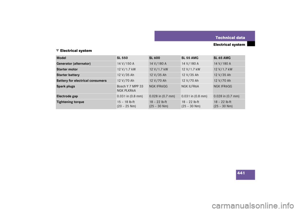
Electrical system
�Electrical system
Model
SL 550
SL 600
SL 55 AMG
SL 65 AMG
Generator (alternator)
14 V/150 A
14 V/180 A
14 V/180 A
14 V/180 A
Starter motor
12 V/1.7 kW
12 V/1.7 kW
12 V/1.7 kW
12 V/1.7 kW
Starter battery
12 V/35 Ah
12 V/35 Ah
12 V/35 Ah
12 V/35 Ah
Battery for electrical consumers
12 V/70 Ah
12 V/70 Ah
12 V/70 Ah
12 V/70 Ah
Spark plugs
Bosch Y 7 MPP 33
NGK PLKR6A
NGK IFR6QG
NGK ILFR6A
NGK IFR6QG
Electrode gap
0.031 in (0.8 mm)
0.028 in (0.7 mm)
0.031 in (0.8 mm)
0.028 in (0.7 mm)
Tightening torque
15 – 18 lb-ft
(20 – 25 Nm)
18 – 22 lb-ft
(25 – 30 Nm)
18 – 22 lb-ft
(25 – 30 Nm)
18 – 22 lb-ft
(25 – 30 Nm)
Page 458 of 473

457 Index
Driving systems 209
ABC 225
Cruise control 209
Distronic* 213
Parktronic* 228
DTR see Distronic*
E
Easy-entry/exit feature 46, 162
Messages in the multifunction
display 375
Electric air pump 389, 410
Electrical outlet see Power outlet
Electro-hydraulic brake system 87, 92
Activation 93
Deactivation 94
Driving hints 95
Messages in the multifunction
display 367, 368
Self-check 94
Warning lamp 92
Electronic Stability Program see ESP
®
Emergency calls
Tele Aid 244, 245
Emergency engine shut-down 426
Emergency operation (Limp-Home
Mode) 179Emergency operations
Automatic transmission (Limp-Home
Mode) 179
Glove box, Unlocking 392
Load assist, Lowering 394
Locking/unlocking the vehicle 391,
393
Remote door unlock, Tele Aid 250
Trunk lid, Releasing from the
inside 117
Trunk lid, Unlocking 392
Emergency Tensioning Device see ETD
Emission control 269
Information label 431
System warranties 10
Vacuum line routing diagram
label 431
Engine
Block heater (Canada only) 317
Break-in recommendations 258
Cleaning 324
Compartment 274
Malfunction indicator lamp 29, 336
Number 431
Poly-V-belt layout 432
Starting 52Tachometer 29
Technical data 433
Turning off 62
Engine coolant see Coolant
Engine oil 275, 446
Adding 278, 444
Additives 446
Checking level, With control
system 276
Checking level, With oil dipstick 278
Consumption 275
Filler neck 278, 279
Messages in the multifunction
display 277, 375
Oil dipstick 278
ESP
®
87, 89
Switch 32
Switching off 91
Switching on 92
Synchronizing 355
Warning lamp 27, 332
ETD 81
Safety guidelines 70
Warning and indictor lamps 342
Exterior lamp switch 128
Exterior rear view mirrors 48, 180
Page 468 of 473

467 Index
Submenus see Control system submenus
Summer opening feature 201
Sun blind see Sunshade
Sun visors 182
Sunshade 208
Closing 208
Opening 208
Suspension tuning
For regular driving style 228
For sporty driving style 228
Suspension tuning (ABC) 225
Switching on headlamps 55
Symbol
Distance warning function* 217
Synchronizing
ESP
®
355
Power windows 198
Synchronizing time with head unit 157
T
Tachometer 29, 138
Tail lamps 398, 402
Cleaning lenses 325
Technical data
Electrical system 441
Main dimensions 442
Rims and tires 435Weights 443
Windshield and headlamp washer
system 452
Tele Aid 244
Emergency calls 245
Information 248
Initiating an emergency call
manually 246
Messages in display 384
Roadside Assistance 247
SOS button 33, 246
Tele Aid system 244
Telephone* 30, 243
Answering a call 166
Dialing 166
Ending a call 167
Loading phone book* 167
Messages in display 384
Operating 165
Redialing 167
Telephones and two-way radios 268
Temperature
Outside temperature indicator 138
Sensor, Interior 33
Tires 292
Tightening torque 412Time
Settings (control system) 157
TIN 314
Tire
Vehicle maximum load on 314
Tire and Loading Information 287
Tire and loading terminology 312
Tire care and maintenance 284
Tire Identification Number see TIN
Tire inflation pressure
Checking 273, 291, 292
Checking tire pressure electronically
with the Advanced Tire Pressure
Monitoring System (Advanced
TPMS)*, (Canada only) 298
Tire inflation pressure see the placard on
the fuel filler flap
Tire inspection 284
Tire load rating 314
Tire ply composition and material
used 314
Tire speed rating 265, 304, 314
Tire terminology 312
Tire traction 265