Page 392 of 473
391 Practical hints
Locking/unlocking in an emergency
�Locking/unlocking in an emergency
Unlocking the vehicle
If you cannot unlock the vehicle using the
SmartKey or KEYLESS-GO*, unlock the
driver’s door and the trunk using the me-
chanical key.
1Mechanical key locking tab
2Mechanical key
�
Move locking tab 1 direction of arrow
and slide the mechanical key 2 out of
the housing.Unlocking the driver’s door
1Unlocking
2Mechanical key
�
Insert mechanical key 2 into the lock
until it stops.
�
Turn mechanical key 2 counterclock-
wise to position 1.
The driver’s door is unlocked. You can
now open the driver’s door.
i
Unlocking the vehicle with the mechanical
key and opening the driver’s door or the trunk
will trigger the anti-theft alarm system
(
�page 96).
To cancel the alarm, insert the SmartKey or the
SmartKey with KEYLESS-GO* in the starter
switch.
Page 393 of 473
 is required to open the trunk lid.
1Unlocking in an emergency
2Handle�
Insert the")
392 Practical hintsLocking/unlocking in an emergencyUnlocking the trunk
A minimum height clearance of 6.2 ft
(1.89 m) is required to open the trunk lid.
1Unlocking in an emergency
2Handle�
Insert the mechanical key into the
trunk lid lock until it stops.
�
Turn the mechanical key counterclock-
wise to position 1.
The trunk is unlocked
�
Pull handle 2 and lift lid.
�
Turn the mechanical key back and re-
move it from the trunk lid lock.Unlocking the glove box
Lockable storage areas in the passenger
compartment include:
�
the glove box
�
the storage compartment under the
armrest
�
the rear storage compartments
If these cannot be unlocked by means of
the SmartKey or the SmartKey with
KEYLESS-GO*, use the mechanical key to
unlock the glove box.1Separately unlocking the glove box
�
Slide mechanical key out of SmartKey
housing (
�page 391).
�
Insert the mechanical key into the
glove box lock and turn it to
position1.
You can now open the glove box.
i
To unlock the remaining storage compart-
ments, the cause for the malfunction of the
SmartKey or the SmartKey with KEYLESS-GO*
must be determined and corrected, see
(
�page 104) and (
�page 109).
Page 394 of 473

393 Practical hints
Locking/unlocking in an emergency
Locking the vehicle
If you cannot lock the vehicle with the
SmartKey, lock it with the mechanical key
as follows:�
Close the passenger door and the
trunk.
�
Press the central locking switch in the
center console (
�page 119).
�
Check whether the locking knob on the
passenger door has moved down.
�
If necessary push it down manually.
�
Remove the mechanical key from of
the SmartKey (
�page 391).
�
Check whether the trunk is locked.
�
If necessary, lock the trunk with the
mechanical key (
�page 117).
Except for the driver’s door, the vehicle
should now be locked.1Locking
2Mechanical key
�
Insert mechanical key 2 (
�page 391)
into the driver’s door lock until it stops.
�
Turn mechanical key 2 clockwise to
position 1.
The driver’s door is locked.
i
Unlocking the glove box with the mechanical
key will trigger the anti-theft alarm system. To
cancel the alarm, do one of the following:
�
Press button Œ or ‹ on the
SmartKey.
�
Insert the SmartKey in the starter switch.
�
Press the KEYLESS-GO* start/stop button
(�page 40).
�
Grasp an outside door handle (vehicles with
KEYLESS-GO* only).
i
This procedure does not arm the anti-theft
alarm system, nor does it lock the fuel filler flap
and the storage compartments.
The storage compartments can be locked
separately (
�page 235).
Page 401 of 473

400 Practical hintsReplacing bulbs4High beam bulbs
5Locking mechanism
6Parking and standing lampsFront turn signal bulb
�
Turn bulb socket 1 counterclockwise
and pull it out.
�
Push the bulb into socket 1, turn
socket 1 counterclockwise and re-
move it.
�
Insert the new bulb in socket 1, push
and turn bulb socket 1 clockwise.
�
Reinsert bulb socket 1 in lamp and
turn bulb socket 1 clockwise.High beam/ high beam flasher bulbs
�
Press ends of headlamp cover tab to-
gether and remove high beam head-
lamp cover 2.
�
Pull the electrical connector off.
�
Turn locking mechanism 5 counter-
clockwise and take out the bulb.
�
Insert the new bulb so that the base lo-
cates in the recess on the holder.
�
Turn locking mechanism 5 clockwise.
�
Plug the connector onto the bulb.
�
Align high beam headlamp cover 2
and click it into place.
Warning!
G
Do not remove the cover for the Xenon or
Bi-Xenon* headlamp. Because of high volt-
age in Xenon and Bi-Xenon* lamps, it is dan-
gerous to replace the bulb or repair the lamp
and its components. We recommend that
you have such work done by a qualified
technician.
Page 403 of 473
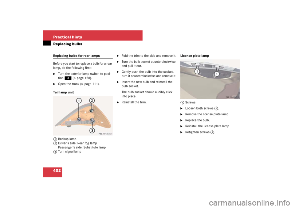
402 Practical hintsReplacing bulbsReplacing bulbs for rear lamps
Before you start to replace a bulb for a rear
lamp, do the following first:�
Turn the exterior lamp switch to posi-
tion M (
�page 128).
�
Open the trunk (
�page 111).
Tail lamp unit
1Backup lamp
2Driver’s side: Rear fog lamp
Passenger’s side: Substitute lamp
3Turn signal lamp
�
Fold the trim to the side and remove it.
�
Turn the bulb socket counterclockwise
and pull it out.
�
Gently push the bulb into the socket,
turn it counterclockwise and remove it.
�
Insert the new bulb and reinstall the
bulb socket.
The bulb socket should audibly click
into place.
�
Reinstall the trim.License plate lamp
1Screws
�
Loosen both screws 1.
�
Remove the license plate lamp.
�
Replace the bulb.
�
Reinstall the license plate lamp.
�
Retighten screws 1.
Page 407 of 473
.
�
Turn spare wheel bracket counter-
clockwise to loosen.
�
Take the spare wheel out of the trunk
(�pag")
406 Practical hintsFlat tirePreparing the vehicle
Prepare the vehicle as described
(�page 405).
�
Turn spare wheel bracket counter-
clockwise to loosen.
�
Take the spare wheel out of the trunk
(�page 389).
Removing tensioning straps
(vehicles with 19" spare wheel only)
A 19" spare wheel has two tensioning
straps on it that must both be removed be-
fore mounting the spare wheel.1Buckle
2Clip
�
Press on both clips 2 simultaneously
to release buckle 1.Lifting the vehicle
�
Prevent the vehicle from rolling away
by blocking wheels with wheel chocks
(not included) or other sizable objects.
When changing wheel on a level sur-
face:�
Place one wheel chock or other
sizable object in front of and anoth-
er wheel chock or sizable object be-
hind the wheel that is diagonally
opposite to the wheel being
changed.
Always try lifting the vehicle using the
jack on a level surface. However,
should circumstances require you to do
so on a hill, place a wheel chock or oth-
er sizable object and the other wheel
chock or sizeable object as follows:
�
Place wheel chocks or other sizable
objects on the downhill side block-
ing both wheels of the axle not be-
ing worked on.
i
The tensioning straps are shown in red for
illustration purposes. The tensioning straps on
the spare wheel of your vehicle are black.
i
Keep the tensioning straps in a safe place.
You will need them to store the spare wheel in
the trunk after use (
�page 390).
Page 410 of 473
409 Practical hints
Flat tire
�
Keeping jack in this position, turn
crank3 clockwise until the jack base
meets the ground. Make sure the jack
is vertical (plumb line).
�
Continue to turn the crank until the tire
is a maximum of 1.2 in (3 cm) from the
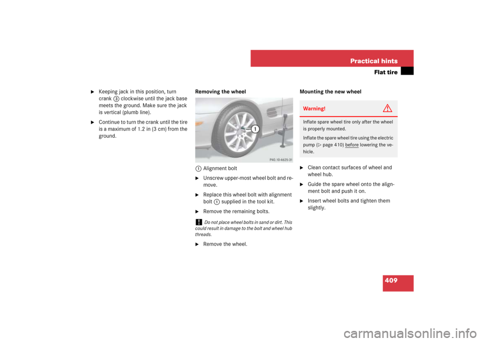
ground.Removing the wheel
1Alignment bolt
�
Unscrew upper-most wheel bolt and re-
move.
�
Replace this wheel bolt with alignment
bolt1 supplied in the tool kit.
�
Remove the remaining bolts.
�
Remove the wheel.Mounting the new wheel
�
Clean contact surfaces of wheel and
wheel hub.
�
Guide the spare wheel onto the align-
ment bolt and push it on.
�
Insert wheel bolts and tighten them
slightly.
!
Do not place wheel bolts in sand or dirt. This
could result in damage to the bolt and wheel hub
threads.
Warning!
G
Inflate spare wheel tire only after the wheel
is properly mounted.
Inflate the spare wheel tire using the electric
pump (
�page 410) before
lowering the ve-
hicle.
Page 413 of 473

412 Practical hintsFlat tireLowering the vehicle�
Lower vehicle by turning crank coun-
terclockwise until the full weight of the
vehicle is resting on the ground.
�
Pull the jack out of the jack support
tube.
1 - 5 Wheel bolts
�
Tighten the five wheel bolts evenly, fol-
lowing the diagonal sequence illustrat-
ed (1 to 5), until all bolts are tight.
Observe a tightening torque of 96 lb-ft
(130 Nm).
�
Before storing the jack in the trunk,
crank back to storage position and fold
in the arm.
Replacing jack support tube cover
�
Slide tongue of cover under the upper
edge of the tube opening.
�
Applying even pressure, press cover
until it snaps into place.
Be careful not to damage the locking
tabs or clamp the plastic retaining
strap.
i
The flat tire may be transported in the trunk
when the retractable hardtop is raised. If avail-
able, use a protective sheet on the spare wheel.
Vehicles with TPMS or Advanced TPMS*:
Do not activate the tire inflation pressure moni-
tor until a full size wheel/tire with functioning
sensor has been placed back into service on the
vehicle.
Warning!
G
Have the tightening torque checked after
changing a wheel. The wheels could come
loose if they are not tightened to a torque of
96 lb-ft (130 Nm).Warning!
G
When turning the wheel wrench to tighten
the wheel bolts, make sure you position
hands on the wrench in such a way that you
avoid injury to yourself, such as scraping
your hands against the wheel. Make sure
turning the wheel wrench will not scratch or
damage the wheel rim.
i
For information on storing the spare wheel
back into the trunk, see “Storing the spare wheel
after use” (
�page 390).
��