Page 497 of 705
.
S 5501Oil dipstick
2Upper mark
3Lower mark�
Pull out oil dipstick1.")
496 OperationEngine compartmentTo check the engine oil level with the oil
dipstick, do the following:�
Open the hood (
�page 492).
S 5501Oil dipstick
2Upper mark
3Lower mark�
Pull out oil dipstick1.
�
Wipe oil dipstick1 clean.
�
Fully insert oil dipstick1 into the dip-
stick guide tube.
�
Pull out oil dipstick1 again after ap-
proximately 3 seconds to obtain accu-
rate reading.The oil level is correct when it is between
lower mark3 (min.) and upper mark2
(max.) mark of the oil dipstick.
�
If necessary, add engine oil.
For adding engine oil (
�page 496).
For more information on engine oil, see the
“Technical data” section (�page 661) and
(
�page 663).
For more information on messages in the
multifunction display concerning engine
oil, see the “Practical hints” section
(�page 602).Adding engine oil
i
The filling quantity between the upper and
lower marks on the oil dipstick is approximately
2.1 US qt. (2.0 l).
!
Only use approved engine oils and oil filters
required for vehicles with Maintenance System
(U.S. vehicles) or FSS PLUS (Canada vehicles).
For a listing of approved engine oils and oil fil-
ters, refer to the Factory Approved Service Prod-
ucts pamphlet in your vehicle literature portfolio,
or contact an authorized Mercedes-Benz Center.
Using engine oils and oil filters of specification
other than those expressly required for the Main-
tenance System (U.S. vehicles) or FSS PLUS
(Canada vehicles), or changing of oil and oil filter
at change intervals longer than those called for
by the Maintenance System (U.S. vehicles) or
FSS PLUS (Canada vehicles) will result in engine
damage not covered by the Mercedes-Benz Lim-
ited Warranty.
Warning!
G
Parts of the engine can become very hot. To
prevent burns, only touch the components
described in the Operator’s Manual and
comply with all relevant safety precautions.
Page 498 of 705

497 Operation
Engine compartment
Example illustration from S 5501Filler cap�
Unscrew filler cap1 from filler neck.
�
Add engine oil as required. Be careful
not to overfill with oil.
Be careful not to spill any oil when adding.
Avoid environmental damage caused by oil
entering the ground or water.
�
Screw filler cap1 back on filler neck.For more information on engine, see the
“Technical data” section (
�page 661) and
(
�page 663).
Transmission fluid level
The transmission fluid level does not need
to be checked. If you notice transmission
fluid loss or gear shifting malfunctions,
have an authorized Mercedes-Benz Center
check the automatic transmission.Active Body Control* (ABC*) fluid level
Regular fluid level check is not required. If
you notice fluid leaks or malfunction mes-
sages in the multifunction display, have an
authorized Mercedes-Benz Center check
the ABC-system.
Coolant level
The engine coolant is a mixture of water
and anticorrosion/antifreeze. To check
the coolant level, the vehicle must be
parked on level ground and the engine
must be cool.
!
Excess oil must be siphoned or drained off.
It will cause damage to the engine and catalytic
converter not covered by the Mercedes-Benz
Limited Warranty.
Warning!
G
In order to avoid any possibly serious burns:�
Use extreme caution when opening the
hood if there are any signs of steam or
coolant leaking from the cooling system,
or if the coolant temperature gauge indi-
cates that the coolant is overheated.
�
Do not remove pressure cap on coolant
reservoir if coolant temperature is
above 158°F (70°C). Allow engine to
cool down before removing cap. The
coolant reservoir contains hot fluid and
is under pressure.
��
Page 499 of 705

498 OperationEngine compartmentThe coolant expansion tank is located on
the passenger side of the engine compart-
ment.Example illustration from S 5501Cap
2Coolant expansion tank
�
Using a rag, turn cap1 slowly approx-
imately one half turn counterclockwise
to release any excess pressure.
�
Continue turning the cap counterclock-
wise and remove it.
The coolant level is correct if the level
�
for cold coolant: reaches the white
marking (plastic bridge) inside the cool-
ant expansion tank
�
for warm coolant: is approximately
0.6 in (1.5 cm) higher
�
Add coolant as required.
�
Replace and tighten cap1.
For more information on coolant, see the
“Technical data” section (
�page 665). Windshield washer system and
headlamp cleaning system
The washer fluid reservoir is located on the
left-hand side of the engine compartment
when looking in the direction of travel. It
supplies the windshield washer system
and headlamp cleaning system* with
washer fluid.S 550 with Airmatic1Cap
�
Using a rag, slowly open the cap approx-
imately
1/2 turn to relieve excess pres-
sure. If opened immediately, scalding
hot fluid and steam will be blown out un-
der pressure.
�
Do not spill antifreeze on hot engine
parts. Antifreeze contains ethylene gly-
col which may burn if it comes into con-
tact with hot engine parts.
��
Page 500 of 705

499 Operation
Engine compartment
Vehicles with ABC*1Cap
Fluid for the windshield washer system and
the headlamp cleaning system is supplied
from the windshield washer reservoir. It
has a capacity of approximately: �
6.93 US qt (6.56 l) in vehicles
with Airmatic*
�
6.76 US qt (6.4 l) in vehicles with ABC*
During all seasons, add MB Windshield
Washer Concentrate “MB SummerFit” to
water. Premix the windshield washer fluid
in a suitable container.
�
To open washer fluid reservoir: pull
tab of cap1 upward.
�
Refill the reservoir with MB Windshield
Washer Concentrate and water (or
commercially available premixed wind-
shield washer solvent/antifreeze, de-
pending on ambient temperatures).
Always use washer solvent/antifreeze
where temperatures may fall below
freezing point. Failure to do so could re-
sult in damage to the washer sys-
tem/reservoir.
�
To close washer fluid reservoir:
press cap1 onto filler hole until it en-
gages.For more information, see “Windshield and
headlamp washer system” (
�page 668).
Warning!
G
Washer solvent/antifreeze is highly flamma-
ble. Do not spill washer solvent/antifreeze
on hot engine parts, because it may ignite
and burn. You could be seriously burned.
!
Only use washer fluid which is suitable for
plastic lenses. Improper washer fluid can dam-
age the plastic lenses of the headlamps.
Page 502 of 705

501 Operation
Tires and wheels
Tire care and maintenance
Regularly check your tire inflation pressure
at least once a month. For more informa-
tion on checking tire inflation pressure,
see “Recommended tire inflation pres-
sure” (
�page 509).Tire inspection
Every time you check your tire inflation
pressure, you should also inspect your
tires for the following:
�
excessive treadwear (
�page 502)
�
cord or fabric showing through the
tire’s rubber
�
bumps, bulges, cuts, cracks or splits in
the tread or side of the tire
Replace the tire if you find any of the above
conditions.
Make sure you also inspect the spare tire
periodically for condition and inflation.
Spare tires will age and degrade over time
even if never used, and thus should be in-
spected and replaced when necessary.Life of tire
The service life of a tire is dependent upon
varying factors including but not limited to:
�
Driving style
�
Tire inflation pressure
�
Distance driven
Warning!
G
Regularly check the tires for damage. Dam-
aged tires can cause tire inflation pressure
loss. As a result, you could lose control of
your vehicle.
Worn, old tires can cause accidents. If the
tire tread is badly worn, or if the tires have
sustained damage, replace them.
Warning!
G
Tires and spare tire should be replaced after
6 years, regardless of the remaining tread.
Page 506 of 705

505 Operation
Tires and wheels
Seating capacity
The seating capacity gives you important
information on the number of occupants
that can be in the vehicle. Observe front
and rear seating capacity. Your vehicle is
equipped with either placard Example A or
placard Example B located on the driver’s
door B-pillar (
�page 503).
Placard (Example A)1Seating capacity
Placard (Example B)1Seating capacitySteps for determining correct load limit
The following steps have been developed
as required of all manufacturers under
Title 49, Code of U.S. Federal Regulations,
Part 575 pursuant to the “National Traffic
and Motor Vehicle Safety Act of 1966”.
Step 1 (Vehicles equipped with placard
Example A)
�
Locate the statement “The combined
weight of occupants and cargo should
never exceed XXX kg or XXX lbs.” on
your vehicle’s placard.
Step 1 (Vehicles equipped with placard
Example B)
�
Locate the heading “Vehicle Capacity
Weight” on your vehicle’s placard.
Step 2
�
Determine the combined weight of the
driver and passengers that will be
riding in your vehicle.
i
Data shown on placard examples are for il-
lustration purposes only. Seating data are specif-
ic to each vehicle and may vary from data shown
in the illustrations below. Refer to placard on ve-
hicle for actual data specific to your vehicle.
��
Page 507 of 705

506 OperationTires and wheelsStep 3�
Subtract the combined weight of the
driver and passengers from XXX kilo-
grams or XXX lbs.
Step 4
�
The resulting figure equals the avail-
able amount of cargo and luggage load
capacity. For example, if the “XXX”
amount equals 1400 lbs. and there will
be five 150 lbs. passengers in your
vehicle, the amount of available cargo
and luggage load capacity is 650 lbs.
(1400 – 750 (5 x 150) = 650 lbs.)
Step 5
�
Determine the combined weight of
luggage and cargo being loaded on the
vehicle. That weight may not safely
exceed the available cargo and luggage
load capacity calculated in step 4.Step 6 (if applicable)
�
If your vehicle will be towing a trailer,
load from your trailer will be trans-
ferred to your vehicle. Consult this
manual to determine how this reduces
the available cargo and luggage load
capacity of your vehicle (
�page 508).
The following table shows examples on
how to calculate total and cargo load
capacities with varying seating configura-
tions and number and size of occupants.
The following examples use a load limit
of 1500 lbs. This is for illustration
purposes only. Make sure you are using
the actual load limit for your vehicle stated
on the vehicle’s placard (
�page 504).
��
Page 508 of 705
507 Operation
Tires and wheels
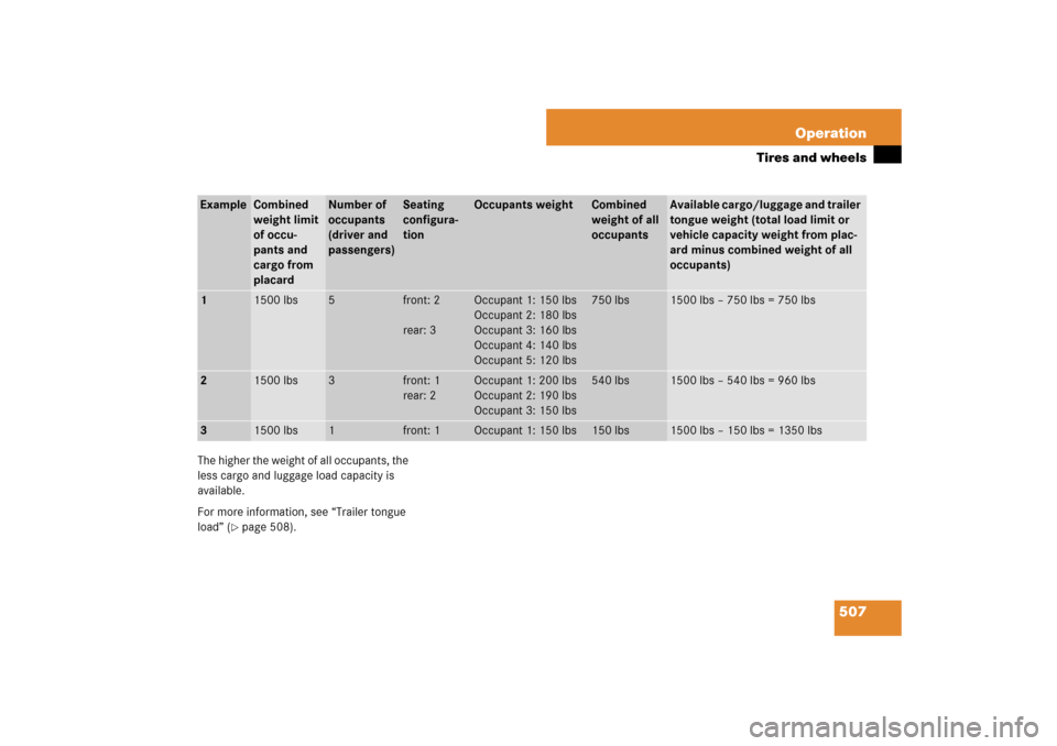
The higher the weight of all occupants, the
less cargo and luggage load capacity is
available.
For more information, see “Trailer tongue
load” (
�page 508).
Example
Combined
weight limit
of occu-
pants and
cargo from
placard
Number of
occupants
(driver and
passengers)
Seating
configura-
tion
Occupants weight
Combined
weight of all
occupants
Available cargo/luggage and trailer
tongue weight (total load limit or
vehicle capacity weight from plac-
ard minus combined weight of all
occupants)
1
1500 lbs
5
front: 2
rear: 3
Occupant 1: 150 lbs
Occupant 2: 180 lbs
Occupant 3: 160 lbs
Occupant 4: 140 lbs
Occupant 5: 120 lbs
750 lbs
1500 lbs – 750 lbs = 750 lbs
2
1500 lbs
3
front: 1
rear: 2
Occupant 1: 200 lbs
Occupant 2: 190 lbs
Occupant 3: 150 lbs
540 lbs
1500 lbs – 540 lbs = 960 lbs
3
1500 lbs
1
front: 1
Occupant 1: 150 lbs
150 lbs
1500 lbs – 150 lbs = 1350 lbs