Page 459 of 570

458 Practical hints
What to do if …
When the message Add 1 qt. engine oil
when next refueling
(Canada: 1 liter)
appears while the engine is running and at
operating temperature, the engine oil level
has dropped to approximately the mini-
mum level.
When this occurs, the warning will first
come on intermittently and then stay on if
the oil level drops further.Visually check for oil leaks. If no obvious oil
leaks are noted, drive to the nearest
service station where the engine oil should
be topped to the required level with an
approved oil specified in the Factory
Approved Service Products pamphlet.
Display symbolDisplay messagePossible cause/consequencePossible solution
NCheck eng. oil level
at next refuelingThe engine oil level is too low.�Check the engine oil level (�page 366).
USA only:
Add 1 qt. engine oil
at next refueling
Canada only:
Add 1 liter engine oil
at next refueling
The engine oil level is too low.�Add engine oil (�page 369) and check
the engine oil level (
�page 366).
Engine oil level
cannot be measuredThe measuring system is
malfunctioning.�Have the measuring system checked by
an authorized Mercedes-Benz Light Truck
Center.
Page 460 of 570
459 Practical hints
What to do if …
Display symbolDisplay messagePossible cause/consequencePossible solution
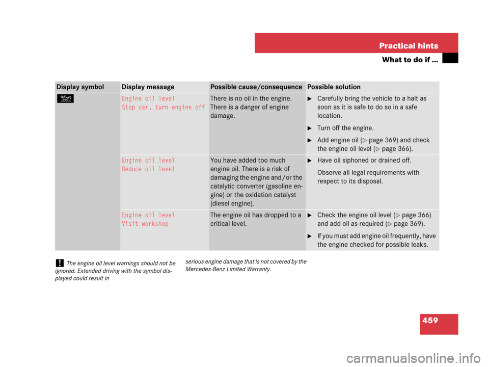
NEngine oil level
Stop car, turn engine offThere is no oil in the engine.
There is a danger of engine
damage.�Carefully bring the vehicle to a halt as
soon as it is safe to do so in a safe
location.
�Turn off the engine.
�Add engine oil (�page 369) and check
the engine oil level (
�page 366).
Engine oil level
Reduce oil levelYou have added too much
engine oil. There is a risk of
damaging the engine and/or the
catalytic converter (gasoline en-
gine) or the oxidation catalyst
(diesel engine).�Have oil siphoned or drained off.
Observe all legal requirements with
respect to its disposal.
Engine oil level
Visit workshopThe engine oil has dropped to a
critical level.�Check the engine oil level (�page 366)
and add oil as required (
�page 369).
�If you must add engine oil frequently, have
the engine checked for possible leaks.
!The engine oil level warnings should not be
ignored. Extended driving with the symbol dis-
played could result inserious engine damage that is not covered by the
Mercedes-Benz Limited Warranty.
Page 475 of 570

474 Practical hints
Where will I find ...?
Vehicle jackThe vehicle jack is located underneath the
storage compartment floor.
Storage position
�Remove vehicle jack from its storage
compartment (
�page 472).
�Push crank handle up.
Operational position
�Turn crank handle clockwise until it
engages (operational position).
Before storing the vehicle jack in its stor-
age compartment:
�The vehicle jack should be fully col-
lapsed.
�The handle must be folded in (storage
position).
Warning!G
The jack is designed exclusively for jacking
up the vehicle at the jack take-up brackets
built into both sides of the vehicle. To help
avoid personal injury, use the jack only to lift
the vehicle during a wheel change. Never
get beneath the vehicle while it is supported
by the jack. Keep hands and feet away from
the area under the lifted vehicle. Always
firmly set parking brake and block wheels
before raising vehicle with jack.
Do not disengage parking brake while the
vehicle is raised. Be certain that the jack is
always vertical (plumb line) when in use,
especially on hills. Always try to use the jack
on level surface.
Make sure the jack arm is fully seated in the
jack take-up bracket. Always lower the
vehicle onto sufficient capacity jackstands
before working under the vehicle.
Page 476 of 570
475 Practical hints
Where will I find ...?
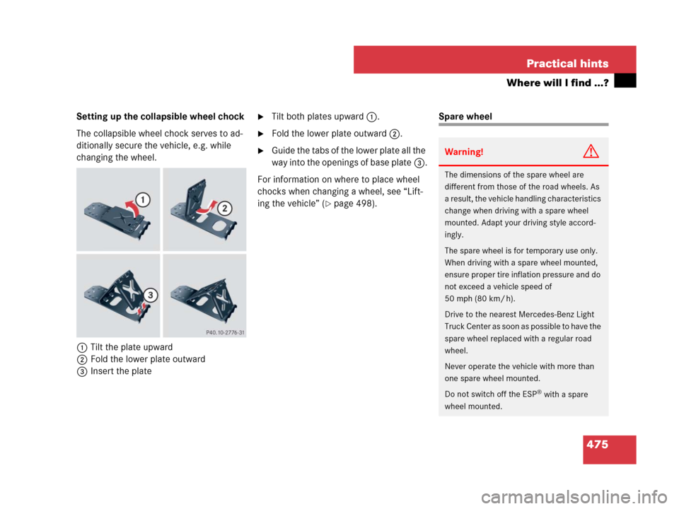
Setting up the collapsible wheel chock
The collapsible wheel chock serves to ad-
ditionally secure the vehicle, e.g. while
changing the wheel.
1Tilt the plate upward
2Fold the lower plate outward
3Insert the plate�Tilt both plates upward1.
�Fold the lower plate outward2.
�Guide the tabs of the lower plate all the
way into the openings of base plate3.
For information on where to place wheel
chocks when changing a wheel, see “Lift-
ing the vehicle” (
�page 498).
Spare wheel
Warning!G
The dimensions of the spare wheel are
different from those of the road wheels. As
a result, the vehicle handling characteristics
change when driving with a spare wheel
mounted. Adapt your driving style accord-
ingly.
The spare wheel is for temporary use only.
When driving with a spare wheel mounted,
ensure proper tire inflation pressure and do
not exceed a vehicle speed of
50 mph (80 km/ h).
Drive to the nearest Mercedes-Benz Light
Truck Center as soon as possible to have the
spare wheel replaced with a regular road
wheel.
Never operate the vehicle with more than
one spare wheel mounted.
Do not switch off the ESP
® with a spare
wheel mounted.
Page 483 of 570
482 Practical hints
Resetting activated head restraints
If the active head restraints have been
triggered in a rear-end collision, the active
head restraints must be reset. Otherwise,
the active head restraints cannot offer any
additional protection in the event of anoth-
er rear-end collision.
You can tell that the active head restraints
have been activated when they have been
moved forward and cannot be adjusted.
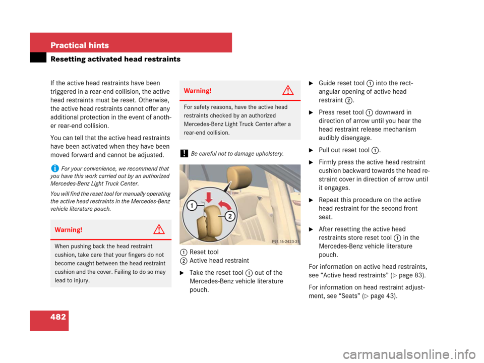
1Reset tool
2Active head restraint
�Take the reset tool1 out of the
Mercedes-Benz vehicle literature
pouch.
�Guide reset tool1 into the rect-
angular opening of active head
restraint2.
�Press reset tool1 downward in
direction of arrow until you hear the
head restraint release mechanism
audibly disengage.
�Pull out reset tool1.
�Firmly press the active head restraint
cushion backward towards the head re-
straint cover in direction of arrow until
it engages.
�Repeat this procedure on the active
head restraint for the second front
seat.
�After resetting the active head
restraints store reset tool1 in the
Mercedes-Benz vehicle literature
pouch.
For information on active head restraints,
see “Active head restraints” (
�page 83).
For information on head restraint adjust-
ment, see “Seats” (
�page 43).
iFor your convenience, we recommend that
you have this work carried out by an authorized
Mercedes-Benz Light Truck Center.
You will find the reset tool for manually operating
the active head restraints in the Mercedes-Benz
vehicle literature pouch.
Warning!G
When pushing back the head restraint
cushion, take care that your fingers do not
become caught between the head restraint
cushion and the cover. Failing to do so may
lead to injury.
Warning!G
For safety reasons, have the active head
restraints checked by an authorized
Mercedes-Benz Light Truck Center after a
rear-end collision.
!Be careful not to damage upholstery.
Page 484 of 570
483 Practical hints
Replacing SmartKey batteries
�Replacing SmartKey batteries
If the batteries in the SmartKey or the
SmartKey with KEYLESS-GO* are
discharged, the vehicle can no longer be
locked or unlocked. It is recommended to
have the batteries replaced at an autho-
rized Mercedes-Benz Light Truck Center.
Batteries contain materials that can harm
the environment if disposed of improperly.
Recycling of batteries is the preferred
method of disposal. Many states require
sellers of batteries to accept old batteries
for recycling.Replacement batteries: Lithium, type
CR 2025 or equivalent.
�Remove the mechanical key from the
SmartKey (
�page 478).
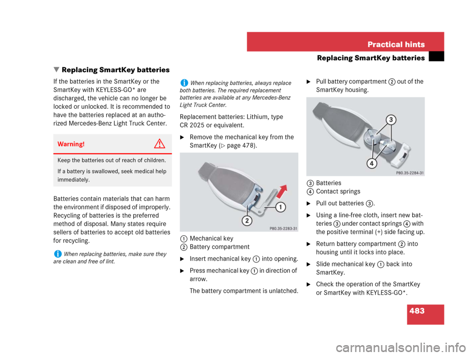
1Mechanical key
2Battery compartment
�Insert mechanical key 1 into opening.
�Press mechanical key 1 in direction of
arrow.
The battery compartment is unlatched.
�Pull battery compartment 2 out of the
SmartKey housing.
3Batteries
4Contact springs
�Pull out batteries3.
�Using a line-free cloth, insert new bat-
teries 3 under contact springs 4 with
the positive terminal (+) side facing up.
�Return battery compartment 2 into
housing until it locks into place.
�Slide mechanical key 1 back into
SmartKey.
�Check the operation of the SmartKey
or SmartKey with KEYLESS-GO*.
Warning!G
Keep the batteries out of reach of children.
If a battery is swallowed, seek medical help
immediately.
iWhen replacing batteries, make sure they
are clean and free of lint.
iWhen replacing batteries, always replace
both batteries. The required replacement
batteries are available at any Mercedes-Benz
Light Truck Center.
Page 487 of 570
486 Practical hints
Replacing bulbs
Notes on bulb replacement
�Only use 12-volt bulbs of the same type
and with the specified watt rating.
�Switch the lights off before changing a
bulb to prevent short circuits.
�Always use a clean lint-free cloth when
handling bulbs.
�Your hands should be dry and free of oil
and grease.
�If the newly installed bulb does not
come on, contact an authorized
Mercedes-Benz Light Truck Center.Have the LEDs and bulbs for the following
lamps replaced by an authorized
Mercedes-Benz Light Truck Center:
�the additional turn signal lamps in the
exterior rear view mirrors
�the high mounted brake lamp
�the Bi-Xenon* low beam lamps
�the Bi-Xenon* high beam flasher spot-
light
�the front side marker lamps
Warning!G
Bulbs and bulb sockets can be very hot.
Allow the lamp to cool down before chang-
ing a bulb.
Keep bulbs out of reach of children.
Halogen lamps contain pressurized gas.
A bulb can explode if you:
�touch or move it when hot
�drop the bulb
�scratch the bulb
Wear eye and hand protection.
Because of high voltage in Xenon lamps, it is
dangerous to replace the bulb or repair the
lamp and its components. We recommend
that you have such work done by a qualified
technician.!Do not replace the bulbs yourself. You could
otherwise damage the LEDs or parts of the vehi-
cle. Only have the LEDs replaced by a qualified
specialist workshop having the necessary skills
and tools for carrying out the work required.
Page 490 of 570
489 Practical hints
Replacing bulbs
Low beam and high beam flasher spot
bulbs
Front turn signal lamp bulbs
�Pull bulb socket 1 out of the head-
lamp housing.
�Pull the turn signal bulb out of bulb
socket 1.
�Insert the new turn signal bulb into bulb
socket 1.
�Insert bulb socket 1 into the head-
lamp housing.Parking and standing lamp bulbs
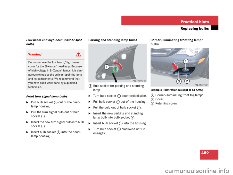
1Bulb socket for parking and standing
lamp
�Turn bulb socket 1 counterclockwise.
�Pull bulb socket 1 out of the housing.
�Pull the bulb out of bulb socket 1.
�Insert the new parking and standing
lamp bulb into bulb socket 1.
�Insert bulb socket 1 into the housing.
�Turn bulb socket 1 clockwise until it
engages.Corner-illuminating front fog lamp*
bulbs
Example illustration (except R 63 AMG)
1Corner-illuminating front fog lamp*
2Cover
3Retaining screw
Warning!G
Do not remove the low beam/high beam
cover for the Bi-Xenon* headlamp. Because
of high voltage in Bi-Xenon* lamps, it is dan-
gerous to replace the bulb or repair the lamp
and its components. We recommend that
you have such work done by a qualified
technician.