Page 474 of 570
473 Practical hints
Where will I find ...?
3Securing hook
�Release securing hook 3 (located be-
low the floor handle) from holder.3Securing hook
4Cargo compartment floor, raised
5Upper cargo compartment lip
�Engage securing hook 3 on upper
cargo compartment lip 5.
You can now access the vehicle tool kit.
To remove the vehicle tool kit storage
well casing, proceed as described
on (
�page 476).6Wheel bolt wrench
7Electric air pump
8Jack
9Spare fuses, fuse extractor, fuse chart
aSpare wheel (collapsible tire)
bAlignment bolt
cTowing eye bolt
dCollapsible wheel chock
eSpare wheel bolts
fVehicle tool kit storage well casing
�To remove jack8, loosen the hook
and loop fastener.
!With the cargo compartment cover blind*
installed behind the third-row seats
(
�page 306), disengage cargo compartment
cover blind* and flip it forward. Otherwise the
strap of the securing hook could damage the
cargo compartment cover blind*.
Page 476 of 570

475 Practical hints
Where will I find ...?
Setting up the collapsible wheel chock
The collapsible wheel chock serves to ad-
ditionally secure the vehicle, e.g. while
changing the wheel.
1Tilt the plate upward
2Fold the lower plate outward
3Insert the plate�Tilt both plates upward1.
�Fold the lower plate outward2.
�Guide the tabs of the lower plate all the
way into the openings of base plate3.
For information on where to place wheel
chocks when changing a wheel, see “Lift-
ing the vehicle” (
�page 498).
Spare wheel
Warning!G
The dimensions of the spare wheel are
different from those of the road wheels. As
a result, the vehicle handling characteristics
change when driving with a spare wheel
mounted. Adapt your driving style accord-
ingly.
The spare wheel is for temporary use only.
When driving with a spare wheel mounted,
ensure proper tire inflation pressure and do
not exceed a vehicle speed of
50 mph (80 km/ h).
Drive to the nearest Mercedes-Benz Light
Truck Center as soon as possible to have the
spare wheel replaced with a regular road
wheel.
Never operate the vehicle with more than
one spare wheel mounted.
Do not switch off the ESP
® with a spare
wheel mounted.
Page 477 of 570
.
Removin")
476 Practical hints
Where will I find ...?
Your vehicle is equipped with a spare
wheel with collapsible tire. The spare
wheel is located underneath the cargo
compartment floor (
�page 472).
Removing the spare wheel
1Retaining screw
2Spare wheel
3Vehicle tool kit storage well casing
�Remove the jack from the vehicle tool
kit (
�page 473).
�Loosen retaining screw 1 by turning it
counterclockwise.
�Turn vehicle tool kit storing well
casing3 by approximately 180°.
The electric air pump (
�page 473)
points towards the rear.
�Remove vehicle tool kit storage well
casing 3.
�Remove spare wheel 2.Reinstalling the spare wheel after use
There are two guide pins in the spare wheel
well that serve to hold the spare wheel in
place.
1Guide pins
iFor information on how to mount the spare
wheel, see “Mounting the spare wheel”
(
�page 498).
iIf retaining screw 1 does not come loose,
turn vehicle tool kit storing well casing 3 slightly
counterclockwise. Retaining screw 1 should
then come loose easily.
Page 498 of 570

497 Practical hints
Flat tire
�Flat tire
Preparing the vehicle
�Park the vehicle in a safe distance from
moving traffic on a hard, flat surface
when possible.
�Turn on the hazard warning flasher
(
�page 152).
�Turn the steering wheel so that the
front wheels are in a straight-ahead
position.
�Set the parking brake (�page 66).
�Set the automatic transmission to
position P (
�page 197).
�Turn off the engine (�page 67).
�Have any passenger exit the vehicle at
a safe distance from the roadway.
�Remove the SmartKey from the starter
switch.Vehicles with KEYLESS-GO*:
�Turn off the engine by pressing the
KEYLESS-GO* button once
(
�page 67).
�Open the driver’s door (this puts
the starter switch in position 0,
same as with the SmartKey re-
moved from the starter switch). The
driver’s door then can be closed
again.
�Remove the KEYLESS-GO*
start/stop button from the starter
switch.
Warning!G
The dimensions of the spare wheel are
different from those of the road wheels. As
a result, the vehicle handling characteristics
change when driving with a spare wheel
mounted. Adapt your driving style accord-
ingly.
The spare wheel is for temporary use only.
When driving with spare wheel mounted,
ensure proper tire inflation pressure and do
not exceed a vehicle speed of
50 mph (80 km/ h).
Drive to the nearest Mercedes-Benz Light
Truck Center as soon as possible to have the
spare wheel replaced with a regular road
wheel.
Never operate the vehicle with more than
one spare wheel mounted.
Do not switch off the ESP
® with a spare
wheel mounted.
iOpen doors only when conditions are safe to
do so.
iYou can use the power outlets in the cargo
compartment or in the second seat row to
operate the electric air pump even when the
ignition is switched off, e.g. in order to inflate the
collapsible tire (
�page 501).
An emergency shut-off feature ensures that the
vehicle’s electrical voltage does not fall below a
minimum level. If the voltage drops to this mini-
mum level, the power outlets are automatically
switched off. This ensures that enough power
remains to start the engine.
Page 499 of 570
.
�Take the wheel wrench and the vehicle
jack from the vehicle tool kit
(")
498 Practical hints
Flat tire
Mounting the spare wheel
Preparing the vehicle
�Prepare the vehicle as described
(
�page 497).
�Take the wheel wrench and the vehicle
jack from the vehicle tool kit
(
�page 473).
�Take the spare wheel from the wheel
well under the cargo compartment
floor (
�page 476).Lifting the vehicle
�Prevent the vehicle from rolling away
by blocking wheels with wheel chocks
or other sizable objects.
One wheel chock is included with the
vehicle tool kit (
�page 473).
When changing wheel on a level surface:
�Place the wheel chock in front of and
another sizable object behind the
wheel that is diagonally opposite to the
wheel being changed.
Always try lifting the vehicle using the jack
on a level surface. However, should cir-
cumstances require you to do so on a hill,
place the wheel chock and another sizable
object as follows:
�Place the wheel chock and another
sizable object on the downhill side
blocking both wheels of the axle not
being worked on.
Warning!G
The jack is designed exclusively for jacking
up the vehicle at the jack take-up brackets
built into both sides of the vehicle. To help
avoid personal injury, use the jack only to lift
the vehicle during a wheel change. Never
get beneath the vehicle while it is supported
by the jack. Keep hands and feet away from
the area under the lifted vehicle. Always
firmly set parking brake and block wheels
before raising vehicle with jack.
Do not disengage parking brake while the
vehicle is raised. Be certain that the jack is
always vertical (plumb line) when in use,
especially on hills. Always try to use the jack
on level surface.
Make sure the jack arm is fully seated in the
jack take-up bracket. Always lower the vehi-
cle onto sufficient capacity jackstands be-
fore working under the vehicle.
Page 501 of 570

500 Practical hints
Flat tire
Removing the wheel
1Alignment bolt
�Unscrew upper-most wheel bolt and
remove.
�Replace this wheel bolt with alignment
bolt1 supplied in the vehicle tool kit
(
�page 472).
�Remove the remaining wheel bolts.
�Remove the wheel.Mounting the spare wheel
1Wheel bolt for 18", 19", 20" and 21"
light alloy wheels and R 63 AMG spare
wheel
2Wheel bolt for 17" light alloy wheels or
18" spare wheel (located in trunk with
spare wheel)�Clean contact surfaces of wheel and
wheel hub.
!Do not place wheel bolts in sand or dirt. This
could result in damage to the bolts and wheel
hub threads.
!Wheel bolts2 must be used when mount-
ing 17" wheels or the 18" spare wheel with
collapsible tire. The use of any wheel bolts other
than wheel bolts2 for 17" wheels or the
18" spare wheel with collapsible tire will physi-
cally damage the vehicle’s brakes.
!To avoid paint damage, place wheel flat
against hub and hold it there while installing first
wheel bolt.
Warning!G
Always replace wheel bolts that are
damaged or rusted.
Never apply oil or grease to wheel bolts.
Damaged wheel hub threads should be
repaired immediately. Do not continue to
drive under these circumstances! Contact
an authorized Mercedes-Benz Light Truck
Center or call Roadside Assistance.
Incorrect wheel bolts or improperly tight-
ened wheel bolts can cause the wheel to
come off. This could cause an accident.
Make sure to use the correct wheel bolts.
Page 502 of 570
501 Practical hints
Flat tire
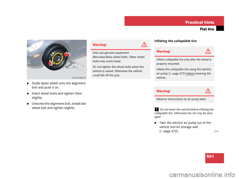
�Guide spare wheel onto the alignment
bolt and push it on.
�Insert wheel bolts and tighten them
slightly.
�Unscrew the alignment bolt, install last
wheel bolt and tighten slightly.Inflating the collapsible tire
�Take the electric air pump out of the
vehicle tool kit storage well
(
�page 472).
Warning!G
Only use genuine equipment
Mercedes-Benz wheel bolts. Other wheel
bolts may come loose.
Do not tighten the wheel bolts when the
vehicle is raised. Otherwise the vehicle
could fall off the jack.Warning!G
Inflate collapsible tire only after the wheel is
properly mounted.
Inflate the collapsible tire using the electric
air pump (
�page 472) before lowering the
vehicle.
Warning!G
Observe instructions on air pump label.
!Do not lower the vehicle before inflating the
collapsible tire. Otherwise the rim may be dam-
aged.
��
Page 503 of 570

502 Practical hints
Flat tire
Electric air pump
1Flap
2On/off switch
3Electrical plug
4Air hose with pressure gauge and vent
screw
5Union nut
�Open flap 1 on electric air pump.
�Pull out electrical plug 3 and air hose
with pressure gauge 4.
�Remove the valve cap from the
collapsible tire valve.
�Screw union nut 5 onto the
collapsible tire valve.
�Insert electrical plug 3 into a power
outlet (
�page 322).
�Turn the SmartKey in the starter switch
to position1.
�Vehicles with KEYLESS-GO*:
Press the KEYLESS-GO start/stop
button once without depressing the
brake pedal.
�Press I on electric air pump switch 2.
The electric air pump should now
switch on and inflate the collapsible
tire.
�Inflate the spare wheel tire to the
recommended tire inflation pressure
given in the “Technical data” section
(
�page 532).
This takes about 5 minutes for the
collapsible tire.
!The cigarette lighter* (�page 319) is not
designed for use with the electric air pump. Use
a power outlet (
�page 322) for electric air
pump operation.
Warning!G
Air hose 4 and union nut5 can become
hot during inflation. Exercise proper caution
to avoid burning yourself when using the
equipment.
!Do not operate the electric air pump longer
than 8 minutes without interruption. Otherwise it
may overheat.
You may operate the electric air pump again
after it has cooled off.
��