Page 498 of 595

497 Practical hints
Where will I find ...?
Vehicle jackThe vehicle jack is located underneath the
cargo compartment floor.
Storage position
�Remove vehicle jack from its storage
compartment (
�page 496).
�Turn crank handle in the direction of ar-
row as far as it will go.
!Vehicles with factory-mounted
running-boards*:
Your vehicle is equipped with a scissors-type
jack (located under the cargo compartment
floor) designed for use with factory-mounted
running boards. Only use this jack when jacking
up vehicles with factory-mounted running boards
as otherwise the vehicle’s underbody can be
damaged. See separate instructions for scis-
sors-type jack.
!To prevent damage, always disengage the
strap of the securing hook and lower the cargo
compartment floor (
�page 495) before closing
the tailgate.
Warning!G
The jack is designed exclusively for jacking
up the vehicle at the jack take-up brackets
built into both sides of the vehicle. To help
avoid personal injury, use the jack only to lift
the vehicle during a wheel change. Never
get beneath the vehicle while it is supported
by the jack. Keep hands and feet away from
the area under the lifted vehicle. Always
firmly set parking brake and block wheels
before raising vehicle with jack.
Do not disengage the parking brake while
the vehicle is raised. Be certain that the jack
is always vertical (plumb line) when in use,
especially on hills. Always try to use the jack
on a level surface.
Make sure that the jack arm is fully seated
in the jack take-up bracket. Always lower
the vehicle onto jackstands of sufficient
capacity before working under the vehicle.
��
Page 502 of 595

501 Practical hints
Unlocking/locking in an emergency
Locking the vehicle
If you cannot lock the vehicle with the
SmartKey or KEYLESS-GO*, lock the vehi-
cle carrying out the following steps.
�Close the front passenger door, the
rear right door and the tailgate.
�Open the driver’s door and the rear left
door.
�Press the central locking switch on the
driver’s door (
�page 130).
The locking knobs of the front passen-
ger door and the rear doors move
down.
If the vehicle battery is disconnected or
drained:
�Press down the locking knobs of
the front passenger door and the
rear doors manually.
�Exit the vehicle.
�Close the driver’s door.
�Enter the vehicle through the rear left
door.
�Press down the locking knob of the
driver’s door.
�Exit the vehicle.
�Close the rear left door.
The vehicle is locked.
Fuel filler flap
�Open the tailgate (�page 124).
The fuel filler flap release is located behind
a cover in the right side trim panel of the
cargo compartment.
1Lock
2Cover
!To prevent inadvertent lockout, make sure
to have the SmartKey or SmartKey with
KEYLESS-GO* with you before proceeding with
the next step. The next step will lock the vehicle.
iThis procedure does not arm the anti-theft
alarm system, nor does it lock the fuel filler flap.
��
Page 516 of 595

515 Practical hints
Replacing bulbs
4Bulb socket of front fog lamp bulb
�Turn bulb socket4 counterclockwise.
�Pull bulb socket4 out of the housing.
�Pull the front fog lamp bulb out of bulb
socket4.
�Insert the new front fog lamp bulb into
bulb socket4.
�Insert bulb socket4 into the housing.
�Turn bulb socket4 clockwise until it
engages.
�Plug in the electrical connector.
�Insert front fog lamp2 back into
bumper.
�Fasten retaining screws3.
�Reinsert cover1 and press it in until it
engages.
Additional turn signal lamps bulbs
The additional turn signal lamps in the
exterior rear view mirrors have LEDs.
If a malfunction occurs or L EDs f a il to f unc -
tion, the entire turn signal unit must be re-
placed. Have the turn signal unit replaced
by an authorized Mercedes-Benz Light
Truck Center.
Replacing bulbs for rear lamps
Before you start to replace a bulb for a rear
lamp, do the following first:
�Turn the exterior lamp switch to
positionM (
�page 145).
Tail lamp unit
�Open the tailgate (�page 124).
iTo access the bulb socket, you have to
remove the cover in the corresponding side trim
panel of the cargo compartment.
Page 518 of 595
517 Practical hints
Replacing bulbs
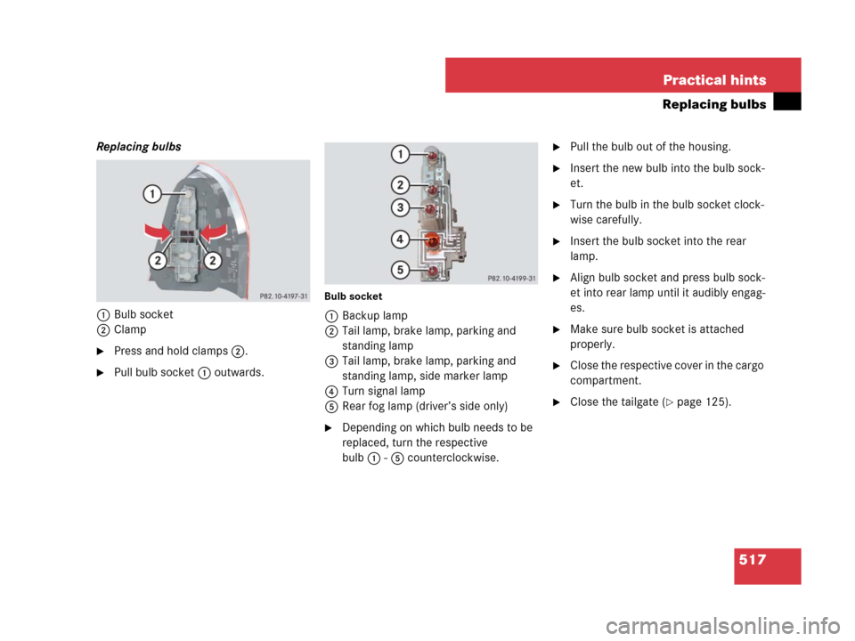
Replacing bulbs
1Bulb socket
2Clamp
�Press and hold clamps2.
�Pull bulb socket1 outwards.
Bulb socket
1Backup lamp
2Tail lamp, brake lamp, parking and
standing lamp
3Tail lamp, brake lamp, parking and
standing lamp, side marker lamp
4Turn signal lamp
5Rear fog lamp (driver’s side only)
�Depending on which bulb needs to be
replaced, turn the respective
bulb1-5 counterclockwise.
�Pull the bulb out of the housing.
�Insert the new bulb into the bulb sock-
et.
�Turn the bulb in the bulb socket clock-
wise carefully.
�Insert the bulb socket into the rear
lamp.
�Align bulb socket and press bulb sock-
et into rear lamp until it audibly engag-
es.
�Make sure bulb socket is attached
properly.
�Close the respective cover in the cargo
compartment.
�Close the tailgate (�page 125).
Page 519 of 595
518 Practical hints
Replacing bulbs
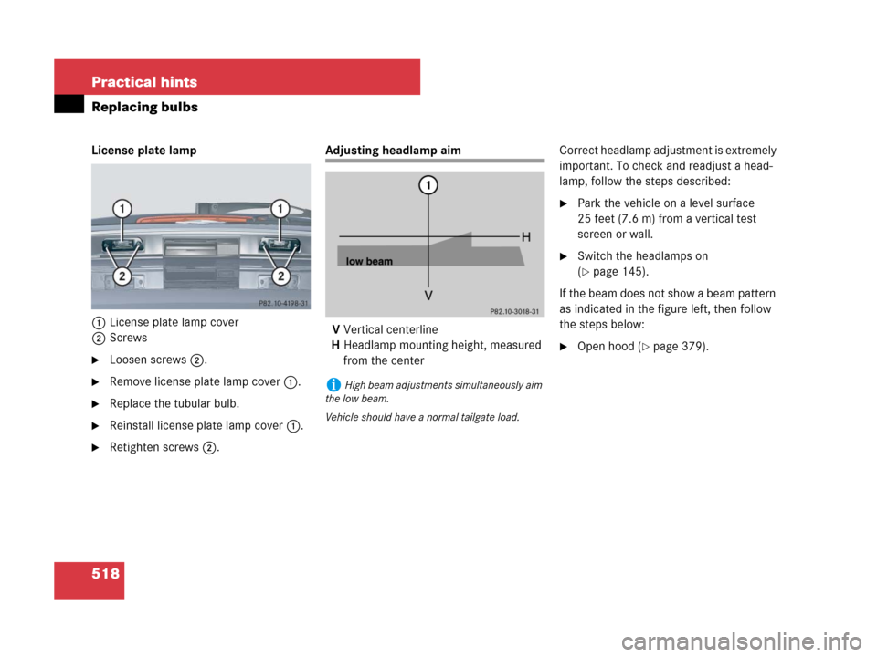
License plate lamp
1License plate lamp cover
2Screws
�Loosen screws2.
�Remove license plate lamp cover1.
�Replace the tubular bulb.
�Reinstall license plate lamp cover1.
�Retighten screws2.
Adjusting headlamp aim
VVertical centerline
HHeadlamp mounting height, measured
from the centerCorrect headlamp adjustment is extremely
important. To check and readjust a head-
lamp, follow the steps described:
�Park the vehicle on a level surface
25 feet (7.6 m) from a vertical test
screen or wall.
�Switch the headlamps on
(
�page 145).
If the beam does not show a beam pattern
as indicated in the figure left, then follow
the steps below:
�Open hood (�page 379).
iHigh beam adjustments simultaneously aim
the low beam.
Vehicle should have a normal tailgate load.
Page 524 of 595

523 Practical hints
Flat tire
�Flat tire
Preparing the vehicle
�Park the vehicle in a safe distance from
moving traffic on a hard, flat surface
when possible.
�Turn on the hazard warning flasher
(
�page 151).
�Turn the steering wheel so that the
front wheels are in a straight-ahead
position.
�Set the parking brake (�page 60).
�Set the automatic transmission to park
positionP (
�page 194).
�Turn off the engine (�page 41).
�Remove the SmartKey from the starter
switch.
Vehicles with KEYLESS-GO*:
�Turn off the engine by pressing the
KEYLESS-GO* button once
(
�page 70).
�Open the driver’s door (this puts
the starter switch in position0,
same as with the SmartKey re-
moved from the starter switch). The
driver’s door then can be closed
again.
�Remove the KEYLESS-GO*
start/stop button from the starter
switch (
�page 43).
�Have any passenger exit the vehicle at
a safe distance from the roadway.
Warning!G
The dimensions of the Minispare wheel are
different from those of the road wheels. As
a result, the vehicle handling characteristics
change when driving with a Minispare wheel
mounted. Adapt your driving style accord-
ingly.
The Minispare wheel is for temporary use
only. When driving with a Minispare wheel
mounted, ensure proper tire pressure and
do not exceed a vehicle speed of
50 mph (80 km/h).
Drive to the nearest Mercedes-Benz Light
Truck Center as soon as possible to have the
Minispare wheel replaced with a regular
road wheel.
Never operate the vehicle with more than
one spare wheel mounted.
Do not switch off the ESP
® when a
Minispare wheel is mounted.
Warning!G
Your vehicle is equipped with air suspen-
sion. Do not open or close any doors or the
tailgate while mounting a spare wheel. The
vehicle could rise or lower to a previously se-
lected level. You or others could be injured
as a result.
iOpen door only when conditions are safe to
do so.
Page 546 of 595
545 Practical hints
Fuses
Fuse box in engine compartment
The fuse box is located on the passenger
side of the engine compartment.
�Open the hood (�page 379).
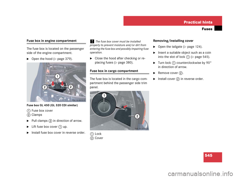
Fuse box GL 450 (GL 320 CDI similar)
1Fuse box cover
2Clamps
�Pull clamps2 in direction of arrow.
�Lift fuse box cover1 up.
�Install fuse box cover in reverse order.
�Close the hood after checking or re-
placing fuses (
�page 380).
Fuse box in cargo compartment
The fuse box is located in the cargo com-
partment behind the passenger side trim
panel.
1Lock
2CoverRemoving/installing cover
�Open the tailgate (�page 124).
�Insert a suitable object such as a coin
into the slot of lock1 (
�page 545).
�Turn lock1 counterclockwise by 90°
in direction of arrow.
�Remove cover2.
�Install cover2 in reverse order.
!The fuse box cover must be installed
properly to prevent moisture and/or dirt from
entering the fuse box and possibly impairing fuse
operation.
Page 576 of 595
 202
Emergency operatio")
575 Index
Emergency operation
Fuel filler flap 501
Locking/unlocking the vehicle 500,
501
Power tilt/sliding sunroof*,
Manual operation 503
Emergency operation
(Limp-Home Mode) 202
Emergency operations
Exit for third-row seats 134
Remote door unlock, Tele Aid 338
Tailgate, Opening from the inside
manually 124
Emergency Tensioning Device see ETD
Emergency, In case of
Battery, Jump starting 538
Engine shut-down 546
First aid kit 495
Flat tire 523
Fuses 544
Hazard warning flasher 151
Instrument cluster, Indicator
lamps 436, 437, 438, 439, 440,
441, 442, 443, 444, 445, 446
Roadside Assistance 12, 336
Towing the vehicle 540Emission control 373
Information label 551
System warranties 10
Vacuum line routing diagram
label 551
Engine
Belt layout 552
Belt layout (GL 320 CDI) 552
Break-in recommendations 381
Cleaning 427
Compartment 379
Emergency engine shut-down 546
Malfunction indicator lamp 29, 472
Maximum engine speed 156, 553
Messages in the
multifunction display 472
Number 551
Starting 57
Starting with KEYLESS-GO* 59
Starting with the SmartKey 58
Tachometer 29, 156
Technical data 553
Turning off with KEYLESS-GO* 70
Turning off with the SmartKey 70Engine coolant see Coolant
Engine oil 381, 562
Adding 382, 562
Additives 562
Changing 382, 562
Checking level 381
Checking with the oil dipstick 381
Consumption 381
Filler neck 382
Messages in the
multifunction display 476
Recommended engine oils and oil
filters 562
Enhanced Off-road Package*
Vehicle level control 285
ESP® 27, 105
Four wheel electronic traction system
with ESP® 105
Messages in the
multifunction display 459, 460
Off-road-ESP® 108
Warning lamp 27, 441, 442