Page 333 of 595

332 Controls in detail
Useful features
Tele Aid
Shortly after the completion of your
Tele Aid acquaintance call, you will receive
a user ID and password. By visiting
www.mbusa.com and selecting “Tele Aid”
(USA only), you will have access to account
information, remote door unlock and
more.The Tele Aid system
(Tele
matic Alarm Identification on
D
emand)
The Tele Aid system consists of three
types of response:
�automatic and manual emergency
�roadside assistance
�information
The Tele Aid system is operational provid-
ing that the vehicle’s battery is charged,
properly connected, not damaged and cel-
lular and GPS coverage is available.
The speaker volume of a Tele Aid call can
be adjusted by using the volume control on
the COMAND system or on the multifunc-
tion steering wheel. To raise, turn the rota-
ry volume control on COMAND system
clockwise or press buttonæ on the
multifunction steering wheel. To lower,
turn the rotary volume control on
COMAND system control counterclock-
wise or press buttonç on the multi-
function steering wheel.
�To activate, press the SOS button, the
Roadside Assistance button• or
the Information button¡, depend-
ing on the type of response required.
!The initial activation of the Tele Aid system
may only be performed by completing the sub-
scriber agreement and placing an acquaintance
call using the ¡button. Failure to complete
either of these steps will result in a system that
is not activated.
If you have any questions regarding activation,
please call the Response Center at
1-800-756-9018 (in the USA) or
1-888-923-8367 (in Canada).
iThe SOS button is located in the overhead
control panel (
�page 34).
The Roadside Assistance button•
(
�page 336) and the Information button¡
(
�page 337) are located below the center arm-
rest cover.
!The Tele Aid system utilizes the cellular
network for communication and the GPS (G
lobal
P
ositioning System) satellites for vehicle loca-
tion. If either of these signals are unavailable, the
Tele Aid system may not function and if this
occurs, assistance must be summoned by other
means.
Page 377 of 595

376 Operation
At the gas station
�Briefly push on fuel filler flap at the po-
sition indicated by the arrow.
The fuel filler flap opens slightly.
�Open the fuel filler flap completely.
�Turn the fuel cap to the left and hold on
to it until possible pressure is released.
�Take off the fuel cap.
�To prevent fuel vapors from escaping
into open air, fully insert filler nozzle
unit.
�Only fill your tank until the filler nozzle
unit cuts out – do not top off or over-
fill.
�Replace the fuel cap by turning it
clockwise until it audibly engages.
�Close the fuel filler flap.
You should hear the latch close shut.
!The fuel filler cap is tethered to the fuel filler
neck. Do not drop the cap. It could damage the
vehicle paint finish.
Warning!G
Overfilling of the fuel tank may create pres-
sure in the system which could cause a gas
discharge. This could cause the gas to spray
back out when removing the fuel pump noz-
zle, which could cause personal injury.
iMake sure to close the fuel filler flap before
locking your vehicle as the flap locking pin
prevents closing after you have locked the
vehicle.
iLeaving the engine running and the fuel cap
open can cause the yellow fuel tank reserve
warning lamp to flash and the ?malfunction
indicator lamp (USA only) or the± malfunc-
tion indicator lamp (Canada only) comes on.
For more information, see “Practical hints”
(
�page 439).
iGasoline engine:
Only use premium unleaded gasoline with a min-
imum Posted Octane Rating of 91 (average of
96 RON/86 MON). Information on gasoline
quality can normally be found on the fuel pump.
Please contact gas station personnel in case
labels on the pump cannot be found.
For more information on gasoline, see “Premium
unleaded gasoline (gasoline engine)”
(
�page 563), see “Fuel requirements”
(
�page 563), and the Factory Approved Service
Products pamphlet (USA only) or contact an
authorized Mercedes-Benz Light Truck Center.
iDiesel engine:
Only use commercially available vehicular
ULTRA-LOW SULFUR DIESEL FUEL
(15 ppm SULFUR MAXIMUM). Information on
diesel quality can normally be found on the fuel
pump. Please contact gas station personnel in
case labels on the pump cannot be found.
For more information on diesel fuels, refer to the
Factory Approved Service Products pamphlet
(USA only) or contact an authorized
Mercedes-Benz Light Truck Center.
��
Page 384 of 595

383 Operation
Engine compartment
The coolant expansion tank is located on
the driver’s side of the engine compart-
ment.
1Cap
2Coolant expansion tank
3Indicator wall
4Coolant level�Using a rag, turn cap1 slowly approx-
imately one half turn counterclockwise
to release any excess pressure.
�Continue turning cap1 counterclock-
wise and remove it.
Coolant level4 is correct if the level:
�for cold coolant: reaches the top of
indicator wall3 visible through the
filling opening
�for warm coolant: is approximately
0.6 in (1.5 cm) higher
�Add coolant as required.
�Replace and tighten cap1.
For more information on coolant, see
“Coolants” (
�page 565).
Warning!G
In order to avoid potentially serious burns:
�Use extreme caution when opening the
hood if there are any signs of steam or
coolant leaking from the cooling system,
or if the coolant temperature gauge indi-
cates that the coolant is overheated.
�Do not remove pressure cap on coolant
reservoir if coolant temperature is
above 158°F (70°C). Allow engine to
cool down before removing cap. The
coolant reservoir contains hot fluid and
is under pressure.
�Using a rag, slowly open the cap approx-
imately 1/2 turn to relieve excess pres-
sure. If opened immediately, scalding
hot fluid and steam will be blown out un-
der pressure.
�Do not spill antifreeze on hot engine
parts. Antifreeze contains ethylene gly-
col which may burn if it comes into con-
tact with hot engine parts.
Page 499 of 595
498 Practical hints
Where will I find ...?
Operational position
�Turn crank handle clockwise.
Before storing the vehicle jack in its stor-
age compartment:
�The vehicle jack should be fully col-
lapsed.
�The handle must be folded in (storage
position).Setting up the collapsible wheel chock
The collapsible wheel chock serves to ad-
ditionally secure the vehicle, e.g. while
changing the wheel.
1Tilt the plate upward
2Fold the lower plate outward
3Insert the plate
�Tilt both plates upward1.
�Fold the lower plate outward2.
�Guide the tabs of the lower plate all the
way into the openings of base plate3.
For information on where to place wheel
chocks when changing a wheel, see “Lift-
ing the vehicle” (
�page 524).
��
Page 500 of 595
.
Removing Minispare wheel
�Remove the jack from the vehicle t")
499 Practical hints
Where will I find ...?
Spare wheelThe Minispare wheel is located underneath
the cargo compartment floor
(
�page 495).
Removing Minispare wheel
�Remove the jack from the vehicle tool
kit (
�page 496).
1Minispare wheel
2Retaining screw
3Vehicle tool kit storage well casing
�Loosen retaining screw2 by turning it
counterclockwise.
�Remove vehicle tool kit storage well
casing3.
You can now access the Minispare wheel.
�Remove Minispare wheel1.
Warning!G
The dimensions of the Minispare wheel are
different from those of the road wheels. As
a result, the vehicle handling characteristics
change when driving with a Minispare wheel
mounted. Adapt your driving style accord-
ingly.
The Minispare wheel is for temporary use
only. When driving with a Minispare wheel
mounted, ensure proper tire inflation
pressure and do not exceed a vehicle speed
of 50 mph (80 km/h).
Drive to the nearest Mercedes-Benz Light
Truck Center as soon as possible to have the
Minispare wheel replaced with a regular
road wheel.
Never operate the vehicle with more than
one spare wheel mounted.
Do not switch off the ESP
® when a
Minispare wheel is mounted.
iFor information on how to mount the
Minispare wheel, see “Mounting the spare
wheel” (
�page 524).
iIf retaining screw2 does not come loose,
turn vehicle tool kit storage well casing3
slightly counterclockwise. Retaining screw2
should then come loose easily.
Page 501 of 595
500 Practical hints
Unlocking/locking in an emergency
Unlocking the vehicle
If you cannot unlock the vehicle with the
SmartKey or KEYLESS-GO*, open the
driver’s door using the mechanical key.Removing the mechanical key
1Mechanical key locking tab
2Mechanical key
�Move locking tab1 in direction of
arrow.
The mechanical key2 comes out.
�Slide mechanical key2 out of the
housing.Unlocking the driver’s door
�Insert mechanical key2 into the
driver’s door lock until it stops.
�Turn mechanical key2 counterclock-
wise to position1 and hold it there.
�Pull the door handle until the locking
knob moves up (
�page 122).
The driver’s door is unlocked.
�Pull the door handle once more to open
the driver’s door.
iUnlocking the driver’s door with the
mechanical key will trigger the anti-theft alarm
system.
To cancel the alarm, insert the SmartKey or
SmartKey with KEYLESS-GO* in the starter
switch.
1Unlocking
2Mechanical key
Page 503 of 595
502 Practical hints
Unlocking/locking in an emergency
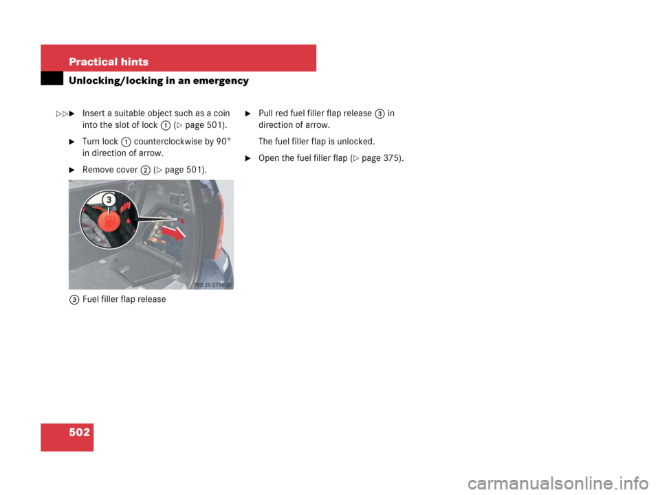
�Insert a suitable object such as a coin
into the slot of lock1 (
�page 501).
�Turn lock1 counterclockwise by 90°
in direction of arrow.
�Remove cover2 (�page 501).
3Fuel filler flap release
�Pull red fuel filler flap release3 in
direction of arrow.
The fuel filler flap is unlocked.
�Open the fuel filler flap (�page 375).
��
Page 504 of 595

503 Practical hints
Opening/closing in an emergency
�Opening/closing in an emergency
Power tilt/sliding sunroof*
You can open or close the tilt/sliding
sunroof manually should an electrical
malfunction occur.
The tilt/sliding sunroof drive is located
behind a cover on the overhead control
panel.
1Cover
�Remove the SmartKey from the starter
switch.Vehicles with KEYLESS-GO*:
�Turn off the engine by pressing the
KEYLESS-GO* start/stop button
(
�page 70).
�Open the driver’s door (this puts
the starter switch in position 0, same
as with the SmartKey removed from
the starter switch). The driver’s door
can then be closed again.
�Press on cover1 at the position indi-
cated by the arrow.
�Take off cover1.
2Crank
�Take crank2 out of the Operator’s
Manual pouch.
�Insert crank2 into hole.
�Turn crank2 clockwise to
�slide sunroof closed
�raise sunroof at the rear
�Turn crank2 counterclockwise to
�slide sunroof open
�lower sunroof at the rear
iThe hole may be covered by a noise
reduction padding. You will then have to push the
crank through the padding at the perforated
mark.
iTurn crank2 slowly and smoothly.
The tilt/sliding sunroof must be synchronized if
it has been operated manually (
�page 255).