Page 399 of 522

398 Practical hintsWhat to do if …Text messagesDisplay message
Possible cause/consequence
Possible solution
ABS
ABS, ESP
inoperative
See Operator’s Man.
ABS, ESP
® as well as PRE-SAFE
®
have switched off due to a malfunc-
tion.
BAS is also switched off.
The brake system is still functioning
normally but without the ABS, BAS,
ESP
® and PRE-SAFE
® available.
�
Continue driving with added caution.
Wheels will lock during hard braking, reduc-
ing steering capability.
�
Have the system checked at an authorized
Mercedes-Benz Center as soon as possible.
Failure to follow these instructions increases
the risk of an accident.
ABS, ESP
unavailable
See Operator’s Man.
ABS, ESP
® as well as PRE-SAFE
®
were deactivated because of insuffi-
cient power supply. The charging
voltage has fallen below 10 volts.
The brake system still functions nor-
mally but without the ABS, BAS,
ESP
® and PRE-SAFE
® available.
When the voltage is above this value again, the
ABS, ESP
® and PRE-SAFE
® are operational
again and the message should disappear.
If the message does not disappear:
�
Have the system checked at an authorized
Mercedes-Benz Center as soon as possible.
Page 413 of 522

412 Practical hintsWhat to do if …Display symbol
Display message
Possible cause/consequence
Possible solution
#
Battery/Alternator
Stop vehicle
The battery is malfunctioning.
The brake system requires electrical en-
ergy and therefore has only limited oper-
ation. Considerably greater brake pedal
force is required and the stopping dis-
tance is increased.
�
Stop the vehicle in a safe location as
soon as it is safe to do so. Adjust driv-
ing to be consistent with reduced
braking responsiveness.
�
Notify an authorized Mercedes-Benz
Center.
Low voltage
Start engine
The battery has insufficient voltage.
�
Start the engine (
�page 52).
(
Right rear backrest
not locked
The rear seat backrest is not engaged.
�
Adjust the rear seat backrest until it is
fully engaged in position.
Left rear backrest
not locked
The rear seat backrest is not engaged.
�
Adjust the rear seat backrest until it is
fully engaged in position.
2
Brakepad wear
The brake pads have reached their wear
limit.
�
Have the brake pads replaced as soon
as possible.
!
Brake pad thickness must be visually in-
spected by a qualified technician at the intervals
specified in the Maintenance Booklet.
Page 421 of 522
420 Practical hintsWhat to do if …Display symbol
Display message
Possible cause/consequence
Possible solution
F
Key
still in vehicle
A SmartKey with KEYLESS-GO* left in the
vehicle was recognized while locking the
vehicle from the outside.
�
Take the SmartKey with
KEYLESS-GO* out of the vehicle.
Please don't
forget your key
This display appears (for a maximum of
60 seconds) if the driver’s door is opened
with the engine shut off and no SmartKey
in the starter switch.
This message is only a reminder.
�
Take the SmartKey or SmartKey with
KEYLESS-GO* with you when leaving
the vehicle.
Remove key
You have forgotten to remove the
SmartKey.
�
Remove the SmartKey from the
starter switch.
Get a new key
The SmartKey is malfunctioning.
�
Contact an authorized
Mercedes-Benz Center.
Page 422 of 522
421 Practical hints
What to do if …
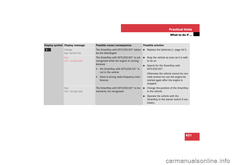
Display symbol
Display message
Possible cause/consequence
Possible solution
F
Change
key batteries
The SmartKey with KEYLESS-GO* batter-
ies are discharged.
�
Replace the batteries (
�page 441).
Key
not recognized
The SmartKey with KEYLESS-GO* is not
recognized while the engine is running
because�
the SmartKey with KEYLESS-GO* is
not in the vehicle
�
there is strong radio-frequency inter-
ference
�
Stop the vehicle as soon as it is safe
to do so.
�
Search for the SmartKey with
KEYLESS-GO*.
Otherwise the vehicle cannot be cen-
trally locked nor can the engine be
started again after the engine is
stopped.
Key
not recognized
The SmartKey with KEYLESS-GO* is mo-
mentarily not recognized.
�
Change the position of the SmartKey
in the vehicle.
�
Operate the vehicle with the
SmartKey in the starter switch if nec-
essary.
Page 433 of 522

432 Practical hintsWhere will I find ...?First aid kit
The first aid kit is in the storage compart-
ment at the front edge of the front passen-
ger seat.
1Tab�
Pull tab1 upward.
�
Fold the covering forward.
�
Remove the first aid kit.
Spare wheel
The spare wheel is located under the trunk
floor.�
Lift the trunk floor and engage the han-
dle in the upper edge of trunk.
�
Remove the luggage box (
�page 433).
1Vehicle tool kit
Wheel bolt wrench and jack
2Spare wheel
3Luggage bowlRemoving the spare wheel
�
Turn luggage bowl3 counterclock-
wise.
�
Remove spare wheel2.
Storing the spare wheel
�
Place spare wheel2 in wheel well.
�
Turn luggage bowl3 clockwise to its
stop to secure the spare wheel.
i
Check expiration dates and contents for
completeness at least once a year and replace
missing/expired items.
i
Vehicles with collapsible tire
(E 63 AMG only):
The electric air pump is located in the storage
wheel casing.
!
Always lower trunk floor before closing
trunk.
Warning!
G
The dimension of the Minispare wheel is dif-
ferent from those of the road wheels. As a
result, the vehicle handling characteristics
change when driving with a spare wheel
mounted.
The spare wheel should only be used tempo-
rarily, and replaced with a regular road
wheel as quickly as possible.
Page 434 of 522
433 Practical hints
Where will I find ...?
In case of a flat tire, you may temporarily
use the spare wheel when observing the
following restrictions:�
Do not exceed a vehicle speed of
50 mph (80 km / h).
�
Drive to the nearest tire repair facility
to have the flat tire repaired or re-
placed as appropriate.
�
Do not operate vehicle with more than
one spare wheel mounted.
For more information, see “Spare wheel”
(
�page 487).
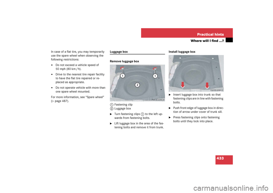
Luggage box
Remove luggage box
1Fastening clip
2Luggage box�
Turn fastening clips1 to the left up-
wards from fastening bolts.
�
Lift luggage box in the area of the fas-
tening bolts and remove it from trunk.Install luggage box
�
Insert luggage box into trunk so that
fastening clips are in line with fastening
bolts.
�
Push front edge of luggage box in direc-
tion of arrow under cover of trunk sill.
�
Press fastening clips onto fastening
bolts until they lock into place.
Page 435 of 522
.
The vehicle tool kit includes:
�
One pair of univ")
434 Practical hintsWhere will I find ...?Vehicle tool kit
The vehicle tool kit is stored in the com-
partment underneath the trunk floor
(�page 432).
The vehicle tool kit includes:
�
One pair of universal pliers
�
One towing eye bolt
�
One wheel wrench
�
One alignment bolt
�
One fuse extractor
�
Spare fuses
�
Collapsible wheel chock
�
A pair of gloves
Setting up the collapsible wheel chock
The collapsible wheel chock serves to
additionally secure the vehicle, e.g. while
changing the wheel.1Tilt the plates upward
2Fold the lower plate outward
3Insert the plate
�
Tilt both plates upward1.
�
Fold the lower plate outward2.
�
Guide the tabs of the lower plate all the
way into the openings of the base
plate3.
Vehicle jackWarning!
G
The jack is designed exclusively for jacking
up the vehicle at the jack take-up brackets
built into both sides of the vehicle. To help
avoid personal injury, use the jack only to lift
the vehicle during a wheel change. Never
get beneath the vehicle while it is supported
by the jack. Keep hands and feet away from
the area under the lifted vehicle. Always
firmly set parking brake and block wheels
before raising vehicle with jack.
Do not disengage parking brake while the
vehicle is raised. Be certain that the jack is
always vertical (plumb line) when in use,
especially on hills. Always try to use the jack
on level surface. Make sure the jack arm is
fully seated in the jack take-up bracket.
Always lower the vehicle onto sufficient
capacity jackstands before working under
the vehicle.
Page 436 of 522
435 Practical hints
Where will I find ...?
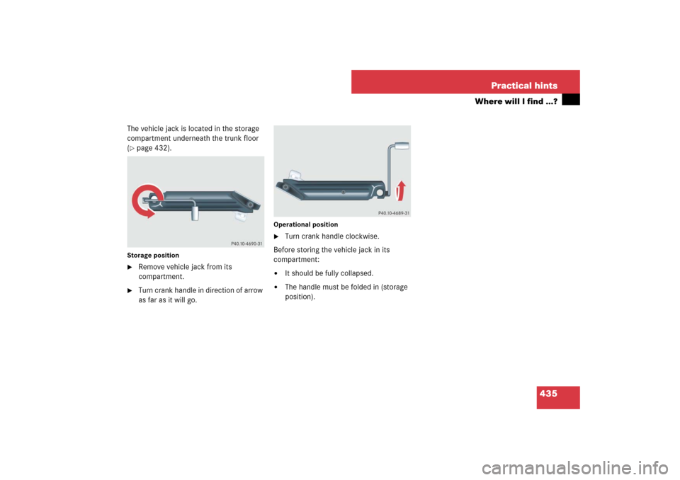
The vehicle jack is located in the storage
compartment underneath the trunk floor
(�page 432).
Storage position�
Remove vehicle jack from its
compartment.
�
Turn crank handle in direction of arrow
as far as it will go.
Operational position�
Turn crank handle clockwise.
Before storing the vehicle jack in its
compartment:
�
It should be fully collapsed.
�
The handle must be folded in (storage
position).