Page 228 of 481

227 Controls in detail
Driving systems
Setting the following distance in
Distronic
You can set the specified following dis-
tance for Distronic by varying the time set-
ting between 1.0 and 2.0 seconds. Using
this time setting and the current speed of
your vehicle, Distronic calculates and sets
the required following distance to the vehi-
cle ahead. The set distance will be shown
in the multifunction display field.
The thumbwheel for making the time set-
ting is located on the lower section of the
center console.1Distance warning function on/off
switch
2Indicator lamp
3Thumbwheel for setting distance
Increasing distance
Increasing the distance setting tells
Distronic to maintain a greater following
distance to the vehicle ahead.
�
Turn thumbwheel3 towards¯.Decreasing distance
Decreasing the distance setting tells
Distronic to maintain a shorter following
distance to the vehicle ahead.
�
Turn thumbwheel3 towards®.
Distance warning function
When Distronic is deactivated, this func-
tion will continue to warn you when recog-
nizing a stationary obstacle or a slower
vehicle moving in the vehicle’s path and
the danger of a collision exists:
�
The distance warning lampl in the
instrument cluster comes on.
�
An intermittent warning will sound if
necessary.
If these warnings are issued, you must
brake manually to maintain a safe distance
and avoid a collision with the vehicle
ahead.
Warning!
G
It is up to the driver to exercise discretion to
select the appropriate setting given road
conditions, traffic, driver’s preferred driving
style and applicable laws and driving recom-
mendations for safe following distance.
Page 235 of 481
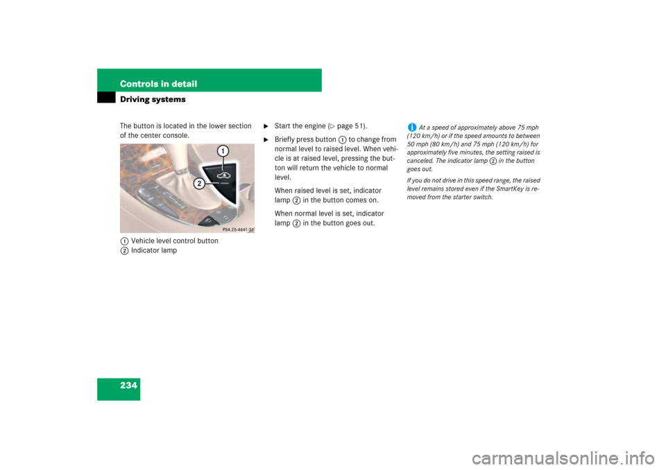
234 Controls in detailDriving systemsThe button is located in the lower section
of the center console.
1Vehicle level control button
2Indicator lamp
�
Start the engine (
�page 51).
�
Briefly press button1 to change from
normal level to raised level. When vehi-
cle is at raised level, pressing the but-
ton will return the vehicle to normal
level.
When raised level is set, indicator
lamp2 in the button comes on.
When normal level is set, indicator
lamp2 in the button goes out.
i
At a speed of approximately above 75 mph
(120 km/h) or if the speed amounts to between
50 mph (80 km/h) and 75 mph (120 km/h) for
approximately five minutes, the setting raised is
canceled. The indicator lamp2 in the button
goes out.
If you do not drive in this speed range, the raised
level remains stored even if the SmartKey is re-
moved from the starter switch.
Page 239 of 481

238 Controls in detailDriving systemsSwitching the Parktronic system
on/off
The Parktronic system can be switched off
manually.
The Parktronic switch is located in the low-
er part of the center console (
�page 30).
1Parktronic switch
2Indicator lampSwitching off the Parktronic system
�
Press Parktronic switch1.
Indicator lamp2 comes on.
Switching on the Parktronic system
�
Press Parktronic switch1 again.
Indicator lamp2 goes out.
Parktronic system malfunction
If only the red distance segments illumi-
nates and an acoustic warning sounds,
there is a malfunction in the Parktronic
system. The Parktronic system will auto-
matically switch off after 20 seconds and
the indicator lamp in the Parktronic switch
comes on.
�
Have the Parktronic system checked
by an authorized Mercedes-Benz
Center as soon as possible.
If only the red distance segments illumi-
nates and no acoustic warning sounds, the
Parktronic system sensors are dirty or
there is an interference from other radio or
ultrasonic signals. The Parktronic system
will automatically switch off after
20 seconds and the indicator lamp in the
Parktronic switch comes on.
�
Switch off the ignition (
�page 38).
�
Clean the Parktronic system sensors
(�page 336).
�
Switch on the ignition (
�page 38).
or
�
Check the Parktronic system operation
at another location to rule out interfer-
ence from outside radio or ultrasonic
signals.
i
The Parktronic system is automatically
switched on when the ignition is switched on
(
�page 38).
Page 241 of 481

Unfolding and loading�
Fold rear armrest down (arrow).
1Cover
2Catch
�
Pull catches2 in direction of arrows.
�
Open the cover1 downwards in the
di")
240 Controls in detailLoading
Ski bag* (Canada only)
Unfolding and loading�
Fold rear armrest down (arrow).
1Cover
2Catch
�
Pull catches2 in direction of arrows.
�
Open the cover1 downwards in the
direction of the arrow.1Hook and loop fastener
�
Unfasten hook and loop fastener1.
�
Pull ski bag into passenger compart-
ment and unfold.
�
Open the front storage compartment in
the rear center console (
�page 248).
�
Remove the cup holder (
�page 248).
Warning!
G
Always fasten items being carried as secure-
ly as possible fastening materials appropri-
ate for the weight and size of the load.
In an accident, during hard braking or sud-
den maneuvers, loose items will be thrown
around inside the vehicle and can cause in-
jury to vehicle occupants unless the items
are securely fastened in the vehicle.
To help avoid personal injury during a colli-
sion or sudden maneuver, exercise care
when transporting cargo. Put luggage or car-
go in the trunk if possible. Do not pile lug-
gage or cargo higher than the seat backs.
Do not place anything on the rear-window
shelf.
Never drive vehicle with trunk open. Deadly
carbon monoxide (CO) gases may enter ve-
hicle interior, resulting in unconsciousness
and death.
Page 243 of 481
242 Controls in detailLoading1Cover�
With insert or cup holder removed, fold
cover1 upward.1Hook
2Eye
�
Connect hook1 to eye2 located in
the front storage compartment in the
rear center console.
�
Tighten strap by pulling at the loose
end (arrow).Unloading and folding
�
Loosen both straps.
�
Disconnect hook1 from eye2.
�
Unload skis.
�
Close flap in trunk.
�
Fold and flatten ski bag lengthwise.
�
Place folded ski bag inside recess of
backrest.
�
Fasten hook and loop fastener
�
Close ski bag compartment cover.
��
Page 246 of 481
245 Controls in detail
Useful features
Opening�
Press button1 right or left and fold
the cover2 sideward.
Rear storage compartment in the rear
center console
1Power outlet (
�page 251)
2Cover
�
Slide cover2 back.Storage compartment in the rear arm-
rest
�
Press the handle upwards and fold the
rear armrest cover up.Storage compartment under the
driver’s seat
1Tab
�
Pull tab1 upward.
�
Fold the covering forward.
i
The mobile phone cradle (
�page 254), the
Roadside Assistance button• and the Infor-
mation button¡ (
�page 257) are located
below the cover2.
!
Do not sit on or lean your body weight
against the armrest when it is folded down, as
you could otherwise damage it.
Page 248 of 481

247 Controls in detail
Useful features
Cup holders Cup holder in the center console
Extending the cup holder
�
Briefly press mark on cup holder.
The cup holder automatically extends
upward.
Retracting the cup holder
�
Press mark on cup holder and push cup
holder in until it engages.
Warning!
G
In order to help prevent spilling liquids on
vehicle occupants and/or vehicle equip-
ment, only use containers that fit into the
cup holder. Use lids on open containers and
do not fill containers to a height where the
contents, especially hot liquids, could spill
during braking, vehicle maneuvers, or in an
accident. Liquids spilled on vehicle occu-
pants may cause serious personal injury.
Liquids spilled on vehicle equipment may
cause damage not covered by the
Mercedes-Benz Limited Warranty.
The cup holder must be extended when in
use with bottles.
When not in use, keep the cup holder
closed. An open cup holder may cause injury
to you or others when contacted during
braking, vehicle maneuvers, or in an acci-
dent.
Keep in mind that objects placed in the cup
holder may come loose during braking, vehi-
cle maneuvers, or in an accident and be
thrown around in the vehicle interior.
Objects thrown around in the vehicle interi-
or may cause an accident and/or serious
personal injury.
Page 249 of 481
248 Controls in detailUseful featuresRemoving the cup holder�
Extend cup holder (
�page 247).
�
Press mark on cup holder and remove
cup holder by pulling it upward.
Reinstalling the cup holder
�
Insert cup holder into opening.
�
Press mark on cup holder and press
cup holder downward until it engages.Cup holder in the rear center console
1Cover
�
Slide cover1 forward.
Removing cup holder1Cup holder
2Locking pin
�
Move pin2 in direction of arrow to un-
lock the cup holder.
�
With the cup holder unlocked, take cup
holder1 out upwards.
Reinstalling cup holder
�
Insert cup holder1.
�
Move pin2 against direction of arrow
to lock the cup holder.
i
The cup holder can be removed for cleaning.
Clean the cup holder with clear, lukewarm water.
!
Make sure that the cup holder is correctly
positioned in the guide while you are reinstalling
it. Otherwise the cup holder can be damaged.
i
The cup holder can be removed for cleaning.
Clean the cup holder with clear, lukewarm water.