Page 642 of 723

639 Practical hints
Replacing SmartKey batteries
�Replacing SmartKey batteries
If the batteries in the SmartKey/SmartKey
with KEYLESS-GO* are discharged, the ve-
hicle can no longer be locked or unlocked.
It is recommended to have the batteries re-
placed at an authorized Mercedes-Benz
Center.Batteries contain materials that can harm
the environment if disposed of improperly.
Recycling of batteries is the preferred
method of disposal. Many states require
sellers of batteries to accept old batteries
for recycling.SmartKey/SmartKey with
KEYLESS-GO*
Replacement batteries: Lithium, type
CR 2025 or equivalent.
�Remove the mechanical key out of the
SmartKey/SmartKey with
KEYLESS-GO* (
�page 635).
1Mechanical key
2Battery compartment
�Insert mechanical key 1 into opening.
�Press mechanical key 1 in direction of
arrow.
The battery compartment is unlatched.
Warning!G
Batteries contain poisonous and corrosive
substances. Therefore keep the batteries
out of reach of children.
If a battery is swallowed, seek medical help
immediately.
iWhen inserting the batteries, make sure
they are clean and free of lint.
iWhen changing batteries, always replace
both batteries.
The required replacement batteries are available
at any authorized Mercedes-Benz Center.
��
Page 646 of 723

643 Practical hints
Replacing bulbs
Notes on bulb replacement�Only use 12-volt-bulbs of the same
type and with the specified watt rating.
�Switch lights off before changing a bulb
to prevent short circuits.
�Always use a clean lint-free cloth when
handling bulbs.
�Your hands should be dry and free of oil
and grease.
�If the newly installed bulb does not
come on, contact an authorized
Mercedes-Benz Center.
Have the LEDs and bulbs for the following
lamps replaced by an authorized
Mercedes-Benz Center:
�the Bi-Xenon lamps
�the front turn signal lamps
�the front fog lamps
�the additional turn signal lamps in the
exterior rear view mirrors
�the parking and standing lamps
�the front side marker lamps
�the high mounted brake lamps
�the brake, tail and rear standing lamps
�the rear side marker lamps
�the rear fog lamp
�the rear turn signal lamps
�the rear side marker lamps
�the license plate lamps
Warning!G
Bulbs and bulb sockets can be very hot. Al-
low the lamp to cool down before changing
a bulb.
Keep bulbs out of reach of children.
Halogen lamps contain pressurized gas. A
bulb can explode if you:
�touch or move it when hot
�drop the bulb
�scratch the bulb
Wear eye and hand protection.
Because of high voltage in Xenon lamps, it is
dangerous to replace the bulb or repair the
lamp and its components. We recommend
that you have such work done by a qualified
technician.
!Do not replace the LEDs yourself. You could
otherwise damage the LEDs or parts of the vehi-
cle. Only have the LEDs replaced by an autho-
rized Mercedes-Benz Center.
iHave the headlamp adjustment checked
regularly.
Page 647 of 723
644 Practical hints
Replacing bulbs
Replacing bulbs for front lamps
You can only change the halogen bulbs for,
high-beam flasher lamp, corner-illuminat-
ing lamp, and IR emitter* lamp.
Before you start to replace a bulb for a
front lamp, do the following first:
�Turn the exterior lamp switch to M
(
�page 363).
�Open the hood (�page 512) (except
for side marker lamps).
Headlamp, left
1Cover
2Tab
�Removing cover: Pull cover1 on
tab2 in direction of arrow and re-
move cover1.
Bi-Xenon headlampsHigh beam flasher lamp
Headlamp, left
1Installation device
�Pull installation device1 up (left
headlamp) or down (right headlamp)
and remove the bulb together with
installation device1 from the head-
lamp.
Warning!G
Do not remove the cover for the Bi-Xenon
headlamp. Because of high voltage in Xenon
lamps, it is dangerous to replace the bulb or
repair the lamp and its components. We rec-
o mme nd th at y ou ha ve s uc h w o rk do n e b y a
qualified technician.
Page 649 of 723

646 Practical hints
Replacing bulbs
IR emitter*
1Bulb holder
2Wire position
�Turn bulb holder1 counterclockwise
until it disengages.
�Take out bulb holder1.
�Press both catches on left and right
sides of bulb holder1 and take bulb
out of holder.
�Insert new bulb into holder until it en-
gages.
�Insert bulb holder1 into guide in
headlamp. Wire2 must point down-
ward and to the right.
�Turn bulb holder1 clockwise until it
engages and wire2 points downward
and to the left.
Additional turn signal lamp bulbs
The additional turn signal lamps in the ex-
terior rear view mirrors have LEDs.
If a malfunction occurs or LEDs fail to func-
tion, the entire turn signal unit must be re-
placed. Have the turn signal unit replaced
by an authorized Mercedes-Benz Center.
Front side marker lamp bulbs
Since replacing the side marker lamp bulbs
is a technically highly demanding process,
we recommend you have the side marker
lamp bulbs replaced by an authorized
Mercedes-Benz Center.Replacing bulbs for the rear lamps
Tail lamp unit
The tail lamp unit is equipped with HiP
bulbs and LED’s.
Warning!G
The bulbs in the tail lamp unit cannot be re-
placed individually. The tail lamp bulbs are
under pressure and could explode during an
attempt to replace them.
If the tail lamps (HiP bulbs and/or LED’S)
are malfunctioning, have them replaced at
an authorized Mercedes-Benz Center.
Page 650 of 723

647 Practical hints
Replacing wiper blades
�Replacing wiper blades
Placing wiper arms in vertical position
Wiper blades in vertical position
�Make sure the hood is fully closed.
Vehicles with SmartKey
�Turn SmartKey in starter switch
position1.
�Turn combination switch to wiper
settingu (
�page 372).
�With wiper arm in vertical position, turn
the SmartKey in starter switch to
position0.
Warning!G
For safety reasons, switch off wipers and re-
move SmartKey from starter switch (vehi-
cles with KEYLESS-GO*: Make sure the
vehicle’s on-board electronics have
status0) before replacing a wiper blade.
Otherwise, the wiper motor could suddenly
turn on and cause injury.
Warning!G
Wiper blades are components that are sub-
ject to wear and tear. Replace the wiper
blades twice a year, preferably in the spring
and fall. Otherwise the windows will not be
properly wiped. As a result, you may not be
able to observe surrounding traffic condi-
tions and could cause an accident.
!To avoid damage to the hood:
�The wiper arms should only be folded for-
ward when in the vertical position.
�Never open the hood when the wiper arm is
folded forward.
!Hold on to the wiper when folding the wiper
arm back. If released, the force of the impact
from the tensioning spring could crack the wind-
shield.
Do not allow the wiper arms to contact the wind-
shield glass without a wiper blade inserted.
For your convenience, we recommend that you
have this work carried out by an authorized
Mercedes-Benz Center.
Page 652 of 723

649 Practical hints
Flat tire
�Flat tire
Preparing the vehicle
�Park the vehicle in a safe distance from
moving traffic on a hard, flat surface
when possible.
�Turn on the hazard warning flashers.
�Turn the steering wheel so that the
front wheels are in a straight ahead
position.
�Shift the automatic transmission toP
(
�page 389).
�Turn off the engine (�page 387).
�Remove the SmartKey from the starter
switch.
Vehicles with SmartKey with
KEYLESS-GO*:
�Turn off the engine by pressing the
KEYLESS-GO* button once
(
�page 388).
�Open the driver’s door (this puts
the starter switch in position0,
same as with the SmartKey re-
moved from the starter switch). The
driver’s door then can be closed
again.
�Have any passenger exit the vehicle at
a safe distance from the roadway.
Mounting the Minispare wheel
iOpen the door only when conditions are safe
to do so.
Warning!G
The dimensions of the Minispare wheel are
different from those of the road wheels. As
a result, the vehicle handling characteristics
change when driving with a Minispare wheel
mounted. Adapt your driving style accord-
ingly.
The Minispare wheel is for temporary use
only. When driving with Minispare wheel
mounted, ensure proper tire inflation
pressure and do not exceed a vehicle speed
of 50 mph (80 km/h).
Contact the nearest Mercedes-Benz Center
as soon as possible to have the Minispare
wheel replaced with a regular road wheel.
Never operate the vehicle with more than
one Minispare wheel mounted.
Do not switch off the ESP
® when a Minis-
pare wheel is mounted.
Page 653 of 723
.
�Take vehicle tool kit and vehicle jack
out of trunk (
�page 632).
�Take the Minispare wheel and w")
650 Practical hints
Flat tire
Preparing the vehicle
�Prepare the vehicle as described
(
�page 649).
�Take vehicle tool kit and vehicle jack
out of trunk (
�page 632).
�Take the Minispare wheel and wheel
bolts out of the trunk (
�page 634).Lifting the vehicle
�Prevent the vehicle from rolling away
by blocking wheels with wheel chocks
or other sizeable objects.
One wheel chock is included with the
vehicle tool kit (
�page 634).
When changing wheel on a level surface:
�Place the wheel chock in front of and
another sizeable suitable object behind
the wheel that is diagonally opposite to
the wheel being changed.
Always try lifting the vehicle using the jack
on a level surface. However, should cir-
cumstances require you to do so on a hill,
place the wheel chock and another size-
able suitable object as follows:
�Place the wheel chock and another
sizeable suitable object on the downhill
side blocking both wheels of the axle
not being worked on.
Warning!G
The jack is designed exclusively for jacking
up the vehicle at the jack take-up brackets
built into both sides of the vehicle. To help
avoid personal injury, use the jack only to lift
the vehicle during a wheel change. Never
get beneath the vehicle while it is supported
by the jack. Keep hands and feet away from
the area under the lifted vehicle. Always en-
gage the electronic parking brake and block
wheels before raising vehicle with jack.
Do not disengage electronic parking brake
while the vehicle is raised. Be certain that
the jack is always vertical (plumb line) when
in use, especially on hills. Always try to use
the jack on level surface. Make sure the jack
arm is fully seated in the jack take-up brack-
et. Always lower the vehicle onto sufficient
capacity jackstands before working under
the vehicle.
Page 654 of 723
651 Practical hints
Flat tire
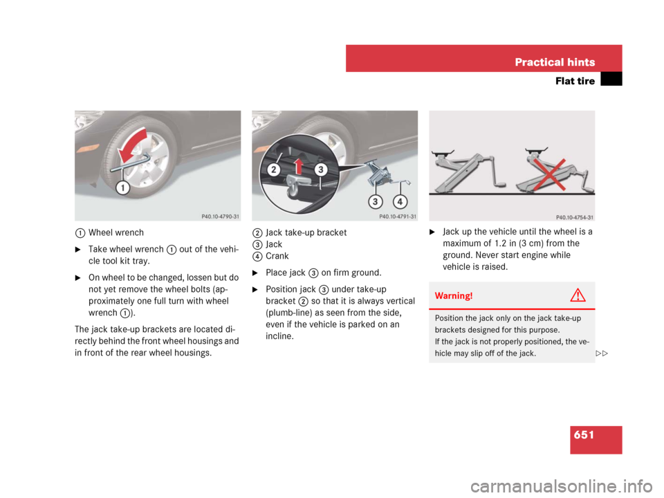
1Wheel wrench
�Take wheel wrench 1 out of the vehi-
cle tool kit tray.
�On wheel to be changed, lossen but do
not yet remove the wheel bolts (ap-
proximately one full turn with wheel
wrench1).
The jack take-up brackets are located di-
rectly behind the front wheel housings and
in front of the rear wheel housings.2Jack take-up bracket
3Jack
4Crank�Place jack3 on firm ground.
�Position jack3 under take-up
bracket2 so that it is always vertical
(plumb-line) as seen from the side,
even if the vehicle is parked on an
incline.
�Jack up the vehicle until the wheel is a
maximum of 1.2 in (3 cm) from the
ground. Never start engine while
vehicle is raised.
Warning!G
Position the jack only on the jack take-up
brackets designed for this purpose.
If the jack is not properly positioned, the ve-
hicle may slip off of the jack.
��