2007 MERCEDES-BENZ C-CLASS ESTATE service
[x] Cancel search: servicePage 126 of 377

Instrument cluste
r 123Instrument cluster
You will find an illustration of the instrumen t
cluster in the "At a glance" section
( Y page 28). G
Risk of accident
No messages can be displayed if instru -
ment cluster and/or the multi-function dis-
play fail .
This means that you will not see information
about the driving situation, such as the
speed, outside temperature, warning/indi-
cator lamps, display messages or system
failures. The vehicle's handling character-
istics may be affected. Adjust your driving
style and speed accordingly.
Immediately consult a qualified specialist
workshop which has the necessary special-
ist knowledge and tools to carry out the
work required. Mercedes-Benz recom-
mends that you use a Mercedes-Benz
Service Centre for this purpose. In particu-
lar, work relevant to safety or on safety-
related systems must be carried out at a
qualified specialist workshop. Activating the multi-function displa
y
X Switch on the ignition.
The multi-function display is also activate d
when you switch on the lights or open th e
driver's door. Adjusting the instrument cluster
lighting
1
Brightness control
X Brighter or dimmer: turn clockwise or
anti-clockwise. Coolant temperature gaug
e
The coolant temperature gauge is in the
instrument cluster on the left-hand side. The
coolant temperature may rise to 120 †under
normal operating conditions and if the con-
centration of antifreeze/corrosion inhibitor is
correct. The coolant temperature may rise to
the top end of the scale at high outside tem-
peratures and on long uphill stretches. Resetting the trip meter
Vehicles with a 4-button multi-function
steering wheel: you can reset the trip meter
in the standard displa ymenu
( Y page 128).
Vehicles with a 12-button luxury multi-
function steering wheel* :you can find th e
"Reset values" function in the Tripmenu in
the on-board computer (Y page 135). Controls
* optional
204_AKB; 2; 3, en-GB
mkalafa,
2007-06-26T23:11:51+02:00 - Seite 123
Page 131 of 377
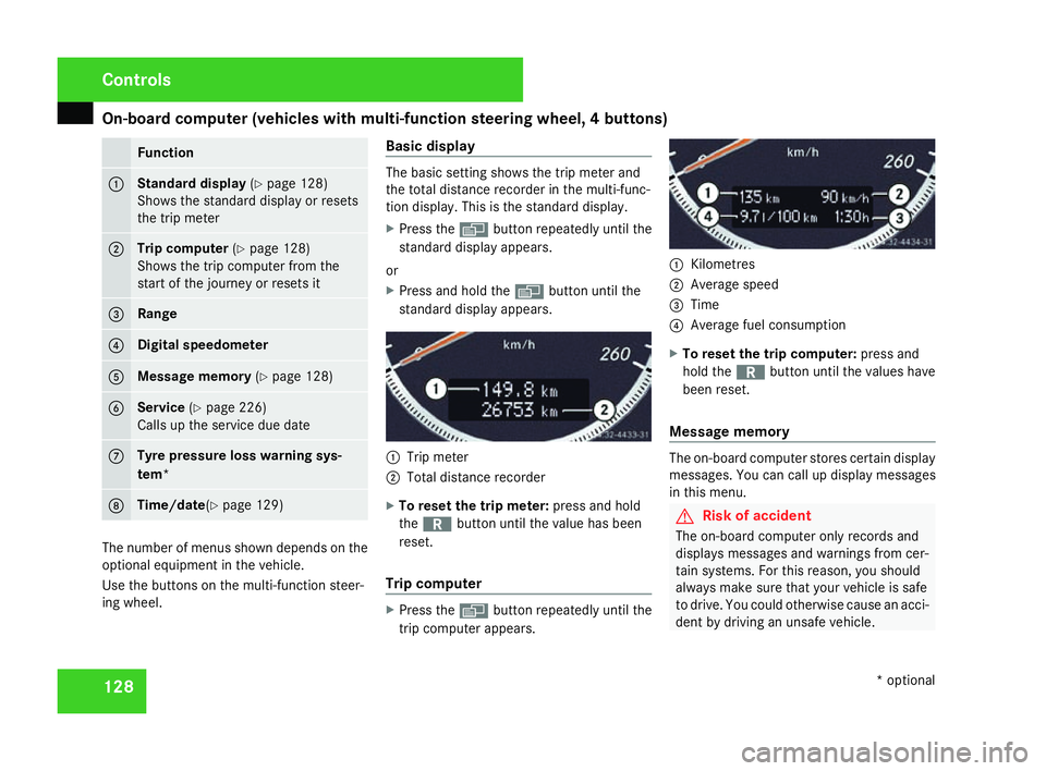
On-board computer (vehicles with multi-function steering wheel, 4 buttons)
128 Function
1 Standard display
(Y page 128 )
Shows the standard display or resets
the trip mete r 2 Trip computer
(Y page 128 )
Shows the trip computer from the
start of the journey or resets it 3 Rang
e 4 Digital speedomete
r5 Message memory
(Y page 128 ) 6 Service
(Y page 226 )
Calls up the service due dat e7 Tyre pressure loss warning sys
-
tem * 8 Time/date
(Y page 129 ) The number of menus shown depends on the
optional equipment in the vehicle.
Use the buttons on the multi-function steer-
ing wheel. Basic display The basic setting shows the trip meter and
the total distance recorder in the multi-func-
tion display. This is the standard display .
X Press the èbutton repeatedly until the
standard display appears.
or
X Press and hold the èbutton until the
standard display appears. 1
Trip meter
2 Total distance recorder
X To reset the trip meter: press and hold
the í button until the value has been
reset .
Trip compute r X
Press the èbutton repeatedly until the
trip computer appears. 1
Kilometres
2 Average spee d
3 Time
4 Average fuel consumption
X To reset the trip computer: press and
hold the íbutton until the values have
been reset .
Message memory The on-board computer stores certain display
messages. You can call up display messages
in this menu. G
Risk of accident
The on-board computer only records and
displays messages and warnings from cer-
tain systems. For this reason, you shoul d
always make sure that your vehicle is safe
to drive. You could otherwise cause an acci-
dent by driving an unsafe vehicle .Cont
rols
* optional
204_AKB; 2; 3, en-GB
mkalafa,
2007-06-26T23:11:51+02:00 - Seite 128
Page 136 of 377
On-board computer (vehicles with the luxury multi-function steering wheel*, 12 buttons)
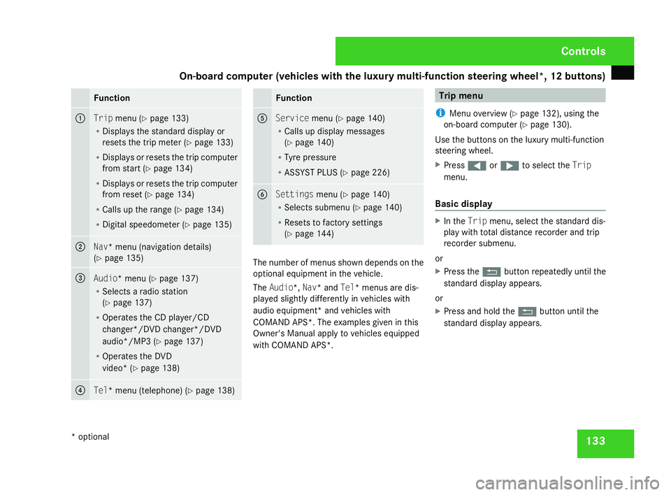
133Function
1
Trip
menu (Y page 133 )
R Displays the standard display or
resets the trip meter (Y page 133 )
R Displays or resets the trip compute r
from start (Y page 134 )
R Displays or resets the trip compute r
from reset (Y page 134 )
R Calls up the range (Y page 134 )
R Digital speedometer (Y page 135 ) 2
Nav* menu (navigation details)
( Y page 135 ) 3
Audio* menu
(Y page 137 )
R Selects a radio station
(Y page 137 )
R Operates the CD player/CD
changer*/DVD changer*/DVD
audio*/MP3 (Y page 137 )
R Operates the DVD
video* (Y page 138 ) 4
Tel* menu (telephone)
(Y page 138 ) Function
5
Service
menu(Y page 140 )
R Calls up display message s
( Y page 140 )
R Tyre pressure
R ASSYST PLUS (Y page 226 ) 6
Settings
menu(Y page 140 )
R Selects submenu (Y page 140 )
R Resets to factory setting s
( Y page 144 ) The number of menus shown depends on the
optional equipment in the vehicle.
The Audio*, Nav* and Tel* menus are dis-
played slightly differently in vehicles with
audio equipment* and vehicles with
COMAND APS*. The examples given in this
Owner's Manual apply to vehicles equipped
with COMAND APS*. Trip men
u
i Menu overview (Y page 132), using the
on-board computer (Y page 130).
Use the buttons on the luxury multi-function
steering wheel.
X Press (or& to select the Trip
menu.
Basic display X
In the Tripmenu, select the standard dis-
play with total distance recorder and trip
recorder submenu.
or
X Press the Lbutton repeatedly until the
standard display appears.
or
X Press and hold the Lbutton until the
standard display appears. Controls
* optional
204_AKB; 2; 3, en-GB
mkalafa,
2007-06-26T23:11:51+02:00 - Seite 133
Page 143 of 377
On-board computer (vehicles with the luxury multi-function steering wheel*, 12 buttons)
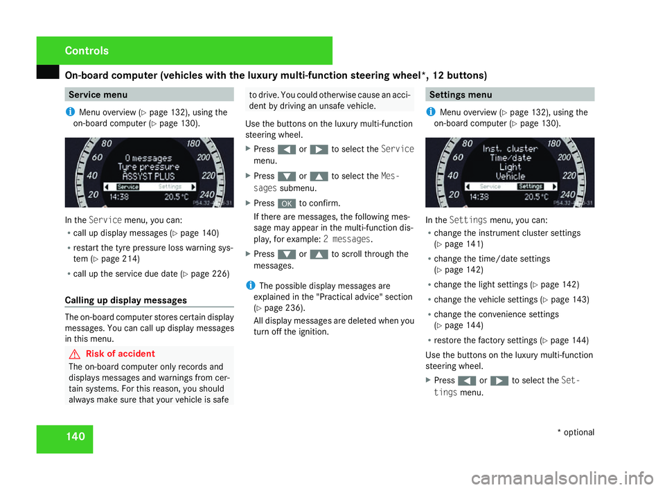
140 Service menu
i Menu overview (Y page 132), using the
on-board computer (Y page 130). In the
Servic emenu, you can:
R call up display messages (Y page 140 )
R restart the tyre pressure loss warning sys-
tem (Y page 214 )
R call up the service due date (Y page 226 )
Calling up display messages The on-board computer stores certain display
messages. You can call up display messages
in this menu. G
Risk of accident
The on-board computer only records and
displays messages and warnings from cer-
tain systems. For this reason, you shoul d
always make sure that your vehicle is safe to drive. You could otherwise cause an acci-
dent by driving an unsafe vehicle .
Use the buttons on the luxury multi-function
steering wheel.
X Press (or& to select the Service
menu.
X Press %or$ to select the Mes-
sages submenu.
X Press #to confirm.
If there are messages, the following mes -
sage may appear in the multi-function dis-
play, for example: 2 messages.
X Press %or$ to scroll through the
messages.
i The possible display messages are
explained in the "Practical advice" section
( Y page 236).
All display messages are deleted when you
turn off the ignition. Settings menu
i Menu overview (Y page 132), using the
on-board computer (Y page 130). In the
Settings menu, you can:
R change the instrument cluster settings
(Y page 141 )
R change the time/date settings
(Y page 142 )
R change the light settings (Y page 142 )
R change the vehicle settings (Y page 143 )
R change the convenience settings
(Y page 144 )
R restore the factory settings (Y page 144 )
Use the buttons on the luxury multi-function
steering wheel.
X Press (or& to select the Set-
tings menu. Controls
* optional
204_AKB; 2; 3, en-GB
mkalafa,
2007-06-26T23:11:51+02:00 - Seite 140
Page 163 of 377
Thermatic
16
0
General notes Thermatic is only operational when the
engine is running. Optimum operation is only
achieved when you drive with the side win-
dows and sliding/tilting sunroof*/panorama
sliding sunroof* closed .
You can allow the air-conditioning system to
adjust automatically or you can adjust it man-
ually.
In automatic mode, Thermatic cools or heats
the vehicle interior according to:
R The selected temperature
R The outside temperature
R The intensity of the sunlight
i Ventilate the vehicle for a brief period
during warm weather, e.g. using the sum-
mer opening feature (Y page 111). This
helps you to achieve the desired interior
temperature more quickly.
The integrated filter filters out most particles
of dust and completely filters out pollen.
i A clogged filter reduces the amount of ai r
supplied to the vehicle interior. For this rea-
son, you should always observe the interval
for replacing the filter, which is specified in
the Service Booklet. As it depends on envi- ronmental conditions, e.g. heavy air pollu-
tion, the interval may be slightly shorter
than stated in the Service Booklet. G
Risk of accident
Follow the settings recommended on the
following pages for heating or cooling. The
windows could otherwise mist up. This may
prevent you from observing the traffic con-
ditions, thereby causing an accident. Activating/deactivating Thermati
c
Thermatic is only operational when the
engine is running.
X To activate :press the ´button.
The indicator lamp in the ´button goes
out. The previously selected settings come
into effect again.
or
X Press the Ubutton.
The indicator lamp in the Ubutton is lit.
Airflow and air distribution are set to auto-
matic mode.
X To deactivate: press the´button.
The indicator lamp in the ´button is lit. i
Select this setting when you drive with the
side windows or the sliding/tilting sun-
roof*/panorama sliding sunroof* open, for
example. When Thermatic is deactivated,
the air supply and air circulation are also
switched off. Only select this setting briefl y
when the side windows and the sliding/
tilting sunroof*/panorama sliding sun-
roof* are closed, otherwise the windows
may mist up. Controlling the air conditioning auto-
matically
i If you have set the air-conditioning sys-
tem to automatic, you only need to set the
temperature. In automatic mode, the air-
flow and air distribution do not need to be
adjusted. The cooling with dehumidifica-
tion function is switched on in automatic
mode. If necessary, cooling with dehumid-
ification can be deactivated.
X Make sure that the key is in position 2in
the ignition lock .
X Set the desired temperature .Cont
rols
* optional
204_AKB; 2; 3, en-GB
mkalafa,
2007-06-26T23:11:51+02:00 - Seite 160
Page 170 of 377
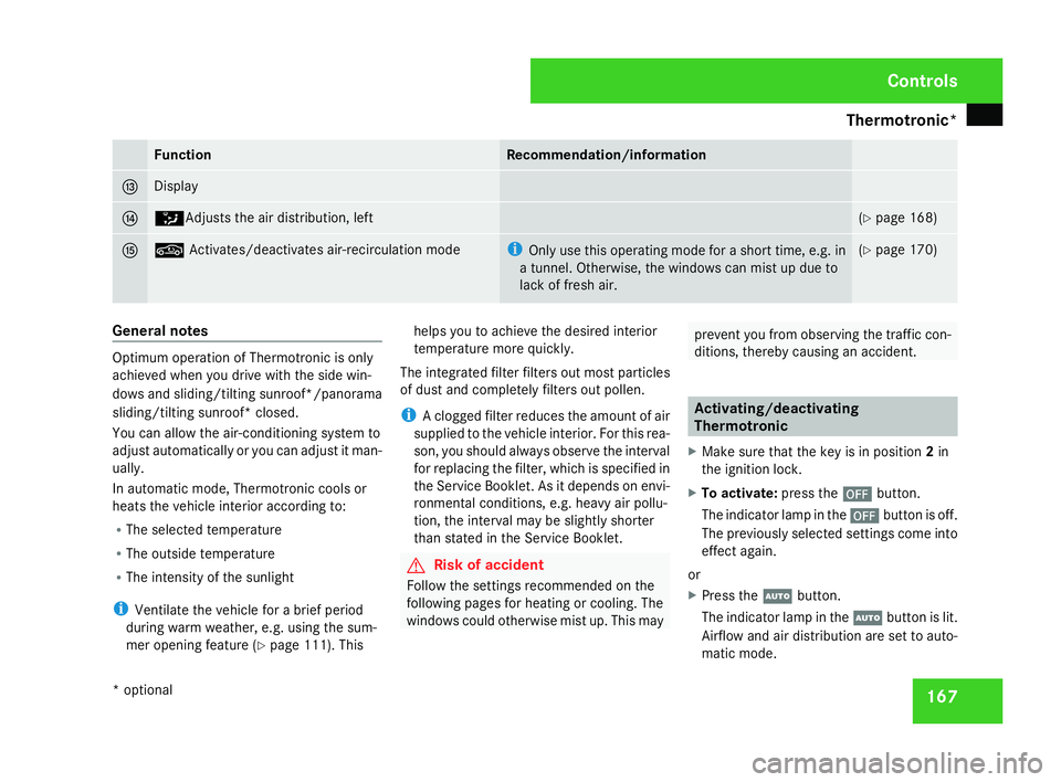
Thermotronic*
16
7 Function Recommendation/information
d Display
e Z
Adjusts the air distribution, left (
Y page 168 ) f ,
Activates/deactivates air-recirculation mod e i
Only use this operating mode for a short time, e.g. in
a tunnel. Otherwise, the windows can mist up due to
lack of fresh air. (
Y page 170 ) General notes
Optimum operation of Thermotronic is only
achieved when you drive with the side win-
dows and sliding/tilting sunroof*/panorama
sliding/tilting sunroof* closed
.
You can allow the air-conditioning system to
adjust automatically or you can adjust it man-
ually.
In automatic mode, Thermotronic cools or
heats the vehicle interior according to:
R The selected temperature
R The outside temperature
R The intensity of the sunlight
i Ventilate the vehicle for a brief period
during warm weather, e.g. using the sum-
mer opening feature (Y page 111). This helps you to achieve the desired interior
temperature more quickly.
The integrated filter filters out most particles
of dust and completely filters out pollen.
i A clogged filter reduces the amount of ai r
supplied to the vehicle interior. For this rea-
son, you should always observe the interval
for replacing the filter, which is specified in
the Service Booklet. As it depends on envi-
ronmental conditions, e.g. heavy air pollu-
tion, the interval may be slightly shorter
than stated in the Service Booklet. G
Risk of accident
Follow the settings recommended on the
following pages for heating or cooling. The
windows could otherwise mist up. This may prevent you from observing the traffic con-
ditions, thereby causing an accident. Activating/deactivatin
g
Thermotroni c
X Make sure that the key is in position 2in
the ignition lock .
X To activate :press the ´button.
The indicator lamp in the ´button is off.
The previously selected settings come int o
effect again.
or
X Press the Ubutton.
The indicator lamp in the Ubutton is lit.
Airflow and air distribution are set to auto-
matic mode. Controls
* optional
204_AKB; 2; 3, en-GB
mkalafa,
2007-06-26T23:11:51+02:00 - Seite 167
Page 185 of 377
Loading and stowing
182 Loading guidelines
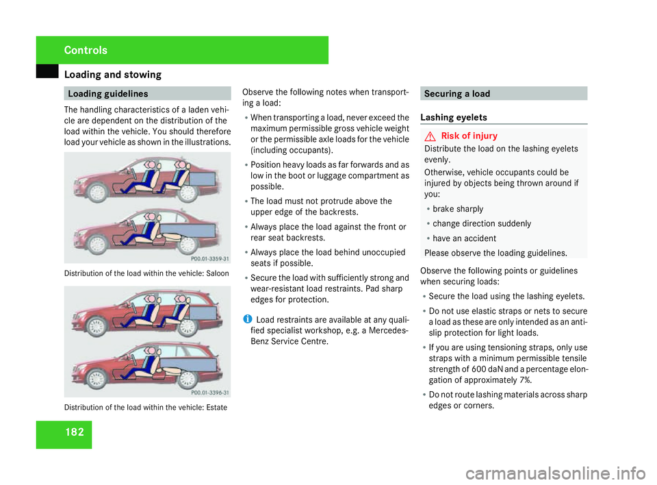
The handling characteristics of a laden vehi-
cle are dependent on the distribution of th e
load within the vehicle. You should therefore
load your vehicle as shown in the illustrations. Distribution of the load within the vehicle: Saloon
Distribution of the load within the vehicle: Estate Observe the following notes when transport
-
ing a load:
R When transporting a load, never exceed the
maximum permissible gross vehicle weight
or the permissible axle loads for the vehicle
(including occupants).
R Position heavy loads as far forwards and as
low in the boot or luggage compartment as
possible.
R The load must not protrude above the
upper edge of the backrests.
R Always place the load against the front or
rear seat backrests.
R Always place the load behind unoccupied
seats if possible.
R Secure the load with sufficiently strong and
wear-resistant load restraints. Pad sharp
edges for protection.
i Load restraints are available at any quali-
fied specialist workshop, e.g. a Mercedes-
Benz Service Centre. Securing a load
Lashing eyelets G
Risk of injury
Distribute the load on the lashing eyelets
evenly .
Otherwise, vehicle occupants could be
injured by objects being thrown around if
you:
R brake sharply
R change direction suddenly
R have an accident
Please observe the loading guidelines.
Observe the following points or guidelines
when securing loads:
R Secure the load using the lashing eyelets.
R Do not use elastic straps or nets to secur e
a load as these are only intended as an anti-
slip protection for light loads.
R If you are using tensioning straps, only use
straps with a minimum permissible tensile
strength of 600 daN and a percentage elon-
gation of approximately 7%.
R Do not route lashing materials across sharp
edges or corners . Cont
rols
204_AKB; 2; 3, en-GB
mkalafa,
2007-06-26T23:11:51+02:00 - Seite 182
Page 202 of 377
Features
199
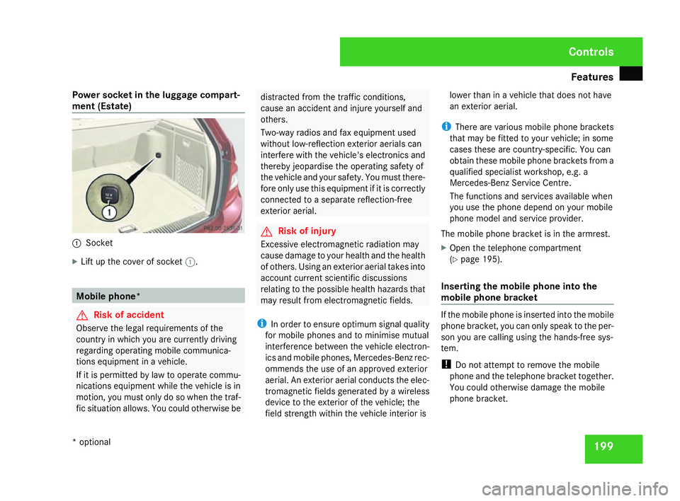
Power socket in the luggage compart
-
ment (Estate ) 1
Socket
X Lift up the cover of socket 1. Mobile phone
* G
Risk of accident
Observe the legal requirements of the
country in which you are currently driving
regarding operating mobile communica -
tions equipment in a vehicle.
If it is permitted by law to operate commu -
nications equipment while the vehicle is in
motion, you must only do so when the traf -
fic situation allows. You could otherwise be distracted from the traffic conditions,
cause an accident and injure yourself and
others.
Two-way radios and fax equipment use
d
without low-reflection exterior aerials can
interfere with the vehicle's electronics and
thereby jeopardise the operating safety of
the vehicle and your safety. You must there-
fore only use this equipment if it is correctly
connected to a separate reflection-free
exterior aerial. G
Risk of injury
Excessive electromagnetic radiation may
cause damage to your health and the health
of others. Using an exterior aerial takes into
account current scientific discussions
relating to the possible health hazards that
may result from electromagnetic fields.
i In order to ensure optimum signal quality
for mobile phones and to minimise mutual
interference between the vehicle electron -
ics and mobile phones, Mercedes-Benz rec -
ommends the use of an approved exterior
aerial. An exterior aerial conducts the elec-
tromagnetic fields generated by a wireless
device to the exterior of the vehicle; the
field strength within the vehicle interior is lower than in a vehicle that does not have
an exterior aerial.
i There are various mobile phone bracket s
that may be fitted to your vehicle; in some
cases these are country-specific. You can
obtain these mobile phone brackets from a
qualified specialist workshop, e.g. a
Mercedes-Benz Service Centre.
The functions and services available when
you use the phone depend on your mobile
phone model and service provider.
The mobile phone bracket is in the armrest.
X Open the telephone compartment
(Y page 195).
Inserting the mobile phone into the
mobile phone bracket If the mobile phone is inserted into the mobile
phone bracket, you can only speak to the per-
son you are calling using the hands-free sys-
tem.
!
Do not attempt to remove the mobile
phone and the telephone bracket together.
You could otherwise damage the mobile
phone bracket. Controls
* optional
204_AKB; 2; 3, en-GB
mkalafa,
2007-06-26T23:11:51+02:00 - Seite 199