Page 210 of 377
Engine compartment
207The electronic ignition system uses high
voltage. For this reason you must never
touch components of the ignition system
(ignition coil, ignition cable, spark plug con-
nector, test socket) when :
R the engine is running
R the engine is being started
R the ignition is switched on and the engine
is being cranked by hand
Vehicles with a diesel engine :
The electronic injection control uses high
voltage. Therefore, never touch fuel injec -
tion system components when:
R the engine is running
R the engine is being started
R the ignition is switched on
X Make sure that the windscreen wipers are
switched off. G
Risk of injury
The windscreen wipers and wiper rod s
could be set in motion.
When the bonnet is open, you or others
could be injured by the wiper rods. Make sure that the windscreen wipers are
switched off and that the key has bee
n
pulled out of the ignition lock before open-
ing the bonnet.
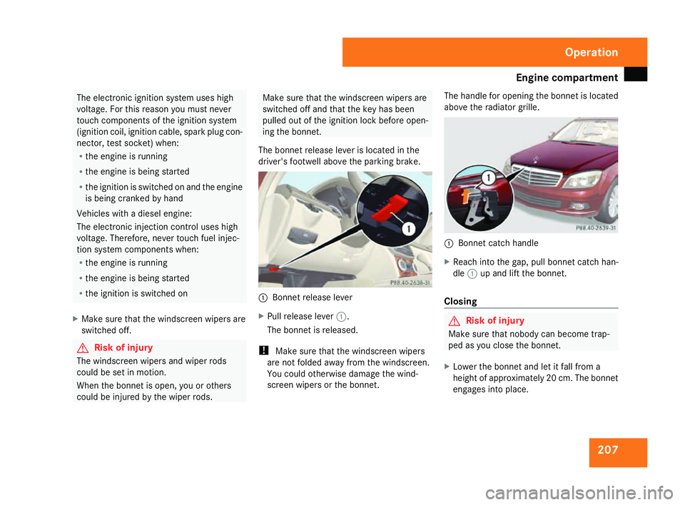
The bonnet release lever is located in the
driver's footwell above the parking brake. 1
Bonnet release lever
X Pull release lever 1.
The bonnet is released.
! Make sure that the windscreen wipers
are not folded away from the windscreen .
You could otherwise damage the wind-
screen wipers or the bonnet. The handle for opening the bonnet is located
above the radiator grille.
1
Bonnet catch handle
X Reach into the gap, pull bonnet catch han -
dle 1up and lift the bonnet.
Closing G
Risk of injury
Make sure that nobody can become trap -
ped as you close the bonnet.
X Lower the bonnet and let it fall from a
height of approximately 20 cm. The bonnet
engages into place. Operation
204_AKB; 2; 3, en-GB
mkalafa,
2007-06-26T23:11:51+02:00 - Seite 207
Page 250 of 377
Display
messages 24
7 Symbol messages
G
Risk of accident and injury
Always have maintenance work carried out at a qualified specialist workshop which has the necessary specialist knowledge and tools to
carry out the work required .
Mercedes-Benz recommends that you use a Mercedes-Benz Service Centre for this purpose.
In particular, work relevant to safety or on safety-related systems must be carried out at a qualified specialist workshop. The operating
safety of the vehicle can be affected if this work is carried out incorrectly. There is a risk of accident and injury. Display messages Possible cause/consequence Possible solution
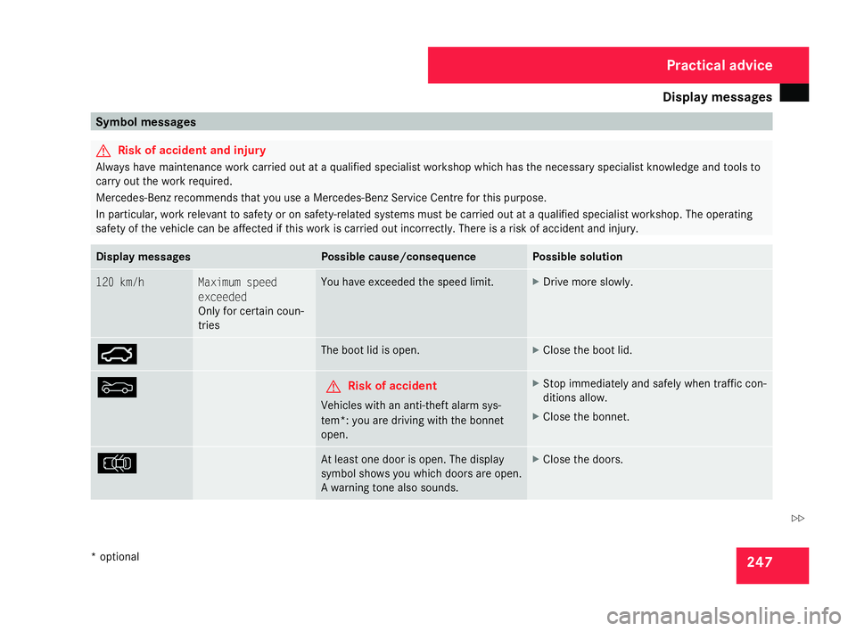
120 km/h Maximum speed
exceeded
Only for certain coun-
tries You have exceeded the speed limit. X
Drive more slowly . Ê The boot lid is open. X
Close the boot lid. Y G
Risk of accident
Vehicles with an anti-theft alarm sys-
tem*: you are driving with the bonne t
open. X
Stop immediately and safely when traffic con-
ditions allow.
X Close the bonnet. V At least one door is open. The displa
y
symbol shows you which doors are open.
A warning tone also sounds. X
Close the doors. Practical advice
* optional
204_AKB; 2; 3, en-GB
mkalafa,
2007-06-26T23:11:51+02:00 - Seite 24
7 Z
Page 311 of 377
Changing the bulbs
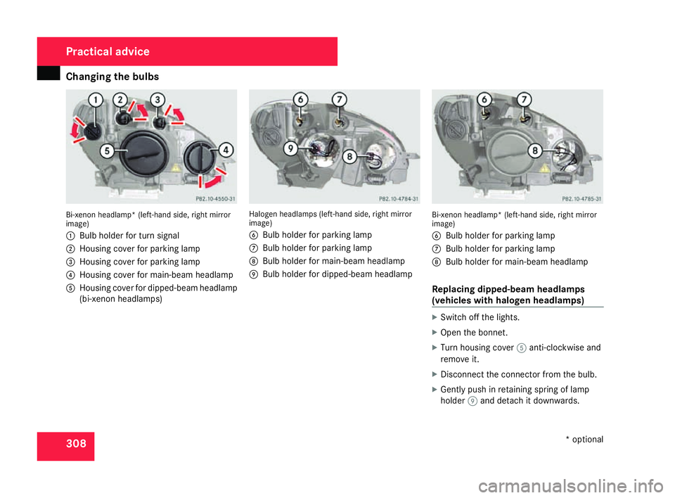
308Bi-xenon headlamp* (left-hand side, right mirror
image)
1
Bulb holder for turn signal
2 Housing cover for parking lamp
3 Housing cover for parking lamp
4 Housing cover for main-beam headlamp
5 Housing cover for dipped-beam headlamp
(bi-xenon headlamps) Halogen headlamps (left-hand side, right mirro
r
image)
6 Bulb holder for parking lamp
7 Bulb holder for parking lamp
8 Bulb holder for main-beam headlamp
9 Bulb holder for dipped-beam headlamp Bi-xenon headlamp* (left-hand side, right mirror
image)
6 Bulb holder for parking lamp
7 Bulb holder for parking lamp
8 Bulb holder for main-beam headlamp
Replacing dipped-beam headlamps
(vehicles with halogen headlamps) X
Switch off the lights .
X Open the bonnet.
X Turn housing cover 5anti-clockwise and
remove it.
X Disconnect the connector from the bulb .
X Gently push in retaining spring of lamp
holder 9and detach it downwards .Practical advice
* optional
204_AKB; 2; 3, en-GB
mkalafa,
2007-06-26T23:11:51+02:00 - Seite 308
Page 312 of 377
Changing the bulbs
309
X
Remove the bulb from the bulb holder,
holding the base (not the glass tube).
X Insert the new bulb so that the base fits flat
into the recess in the bulb holder.
X Clip in the retaining spring of bulb
holder 9.
X Attach the connector to the bulb .
X Put on the housing cover and turn it clock -
wise until it clips into place.
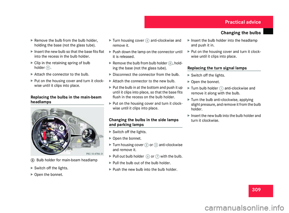
Replacing the bulbs in the main-beam
headlamp s 8
Bulb holder for main-beam headlamp
X Switch off the lights .
X Open the bonnet. X
Turn housing cover 4anti-clockwise and
remove it.
X Push down the lamp on the connector until
it is released.
X Remove the bulb from bulb holder 8, hold-
ing the base (not the glass tube).
X Disconnect the connector from the bulb .
X Attach the connector to the new bulb .
X Put the bulb in at the bottom and push it up
until it clips into place, so that the base fits
flush in the recess on the bulb holder.
X Put on the housing cover and turn it clock -
wise until it clips into place .
Changing the bulbs in the side lamps
and parking lamps X
Switch off the lights .
X Open the bonnet.
X Turn housing cover 2or3 anti-clockwis e
and remove it.
X Pull out bulb holder 6or7 with the bulb.
X Pull the bulb out of the bulb holder.
X Push the new bulb into the bulb holder. X
Insert the bulb holder into the headlamp
and push it in.
X Put on the housing cover and turn it clock -
wise until it clips into place.
Replacing the turn signal lamps X
Switch off the lights .
X Open the bonnet.
X Turn bulb holder 1anti-clockwise and
remove it along with the bulb.
X Turn the bulb anti-clockwise, applying
slight pressure, and remove it from the bulb
holder.
X Insert the new bulb into the bulb holder and
turn it clockwise. Practical advice
204_AKB; 2; 3, en-GB
mkalafa
, 2007-06-26T23:11:51+02:00 - Seite 309
Page 329 of 377
Battery
32
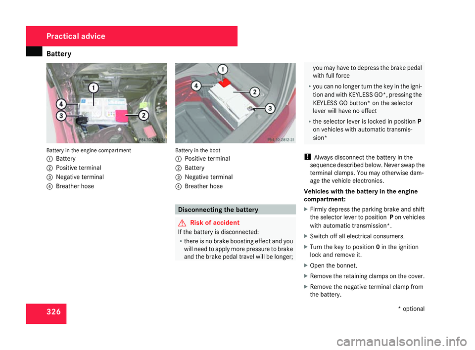
6 Battery in the engine compartment
1
Batter y
2 Positive terminal
3 Negative terminal
4 Breather hos e Battery in the boo
t
1 Positive terminal
2 Battery
3 Negative terminal
4 Breather hos e Disconnecting the batter
y G
Risk of accident
If the battery is disconnected:
R there is no brake boosting effect and yo u
will need to apply more pressure to brak e
and the brake pedal travel will be longer ; you may have to depress the brake peda
l
with full force
R you can no longer turn the key in the igni-
tion and with KEYLESS GO*, pressing th e
KEYLESS GO button* on the selector
lever will have no effect
R the selector lever is locked in position P
on vehicles with automatic transmis-
sion*
! Always disconnect the battery in the
sequence described below. Never swap the
terminal clamps. You may otherwise dam-
age the vehicle electronics.
Vehicles with the battery in the engine
compartment:
X Firmly depress the parking brake and shift
the selector lever to position Pon vehicles
with automatic transmission*.
X Switch off all electrical consumers .
X Turn the key to position 0in the ignition
lock and remove it.
X Open the bonnet.
X Remove the retaining clamps on the cover .
X Remove the negative terminal clamp from
the battery. Practical advice
* optional
204_AKB; 2; 3, en-GB
mkalafa,
2007-06-26T23:11:51+02:00 - Seite 32
6
Page 336 of 377
Fuse
s 333
!
Only use fuses that have been approved
for Mercedes-Benz vehicles and which
have the correct amperage for the system
concerned. Otherwise, components or sys-
tems could be damaged.
The fuses are located in various fuse boxes :
R Dashboard fuse box* on driver's side
R Fuse box in the engine compartment on the
driver's sid e
R Fuse box in the boot/luggage compart-
ment on the right-hand side of the vehicle
Fuse allocation chart The fuse allocation chart is located with the
vehicle tool kit (Y page 234) in the stowage
compartment under the boot/luggage com-
partment floor. The fuse amperage is also
indicated there. Before changing a fuse
X Park the vehicle.
X Switch off all electrical consumers .
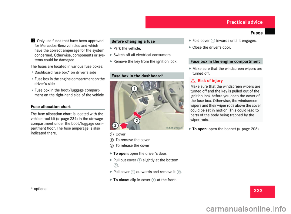
X Remove the key from the ignition lock. Fuse box in the dashboard*
1
Cove r
2 To remove the cover
3 To release the cover
X To open: open the driver’s door.
X Pull out cover 1slightly at the bottom
3 .
X Pull cover 1outwards and remove it 2.
X To close: clip in cover 1at the front. X
Fold cover 1inwards until it engages.
X Close the driver's door . Fuse box in the engine compartment
X Make sure that the windscreen wipers are
turned off. G
Risk of injury
Make sure that the windscreen wipers are
turned off and the key is pulled out of the
ignition lock before you open the cover of
the fuse box. Otherwise, the windscreen
wipers and their wiper rods above the cove r
could be set in motion. This could lead to
parts of the body being trapped by the
wiper rods.
X To open: open the bonnet (Y page 206). Practical advice
* optional
204_AKB; 2; 3, en-GB
mkalafa,
2007-06-26T23:11:51+02:00 - Seite 333
Page 337 of 377
Fuse
s 3341
Clamps
2 Line
X Remove moisture from the fuse box usin g
a dry cloth .
X Unclip line 2from the lid .
X Fold clamps 1upwards.
X Lift off the fuse box cover towards the front
of the vehicle .
X To close: check whether the rubber seal is
positioned correctly in the lid.
X Insert the lid into the retainer at the rear of
the fuse box.
X Press the lid down and secure with clamps
1 .
X Clip line 2onto the lid. X
Close the bonnet (Y page 206). Fuse box in the boot (Saloon)
X To open: open the boot lid. 1
Locking mechanism
2 Side trim panel
X Turn locking mechanism 1.
X Fold side trim panel 2downwards. Fuse box in the luggage compartment
(Estate)
X To open: open the tailgate . 1
Handl e
X Pull handle 1.
X Fold side trim panel downwards. Practical advic
e
204_AKB; 2; 3, en-GB
mkalafa,
2007-06-26T23:11:51+02:00 - Seite 334