2007 MERCEDES-BENZ C-CLASS ESTATE height
[x] Cancel search: heightPage 155 of 377
Driving sys
tems 15
2foot off the brake pedal and carefully
depress the accelerator pedal
R in vehicles with automatic transmis-
sion* you take your foot off the brak e
pedal and carefully depress the acceler -
ator pedal
i Once you have taken your foot off the
brake pedal, the vehicle is held for around
one second.
Hill start assist does not function:
R if you are pulling away on a level surface or
a downhill gradien t
R in vehicles with automatic transmission *if
the gear selector lever is in the Nposition
R if the vehicle is secured with the parking
brak e
R if ES P®
is defectiv e ADVANCED AGILITY package with
sports mode*
The most important part of the ADVANCE D
AGILITY package with sports mode is the
adjustable suspension system. This automat-
ically controls and adapts the suspension to
the respective driving situation.
The calibration of the suspension depends
on:
R your driving style
R the road surface conditions
R your individual selection; see also the fol-
lowing description
If your vehicle is equipped with automati c
transmission*, the ADVANCED AGILITY pack-
age with sports mode also includes steering-
wheel gearshift paddles* with a manua l
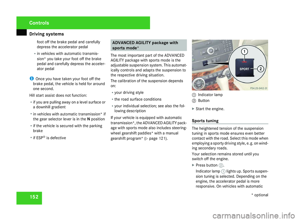
gearshift program* (Y page 121). 1
Indicator lamp
2 Button
X Start the engine.
Sports tuning The heightened tension of the suspensio
n
tuning in sports mode ensures even better
contact with the road. Select this mode when
employing a sporty driving style, e. g. on wind-
ing secondary roads .
Your selection remains stored until you
switch off the engine.
X Press button 2.
Indicator lamp 1lights up. Sports suspen -
sion tuning is selected. Depending on the
engine, the accelerator pedal is more
responsive. On vehicles with automatic Controls
* optional
204_AKB; 2; 3, en-GB
mkalafa,
2007-06-26T23:11:51+02:00 - Seite 152
Page 210 of 377
Engine compartment
207The electronic ignition system uses high
voltage. For this reason you must never
touch components of the ignition system
(ignition coil, ignition cable, spark plug con-
nector, test socket) when :
R the engine is running
R the engine is being started
R the ignition is switched on and the engine
is being cranked by hand
Vehicles with a diesel engine :
The electronic injection control uses high
voltage. Therefore, never touch fuel injec -
tion system components when:
R the engine is running
R the engine is being started
R the ignition is switched on
X Make sure that the windscreen wipers are
switched off. G
Risk of injury
The windscreen wipers and wiper rod s
could be set in motion.
When the bonnet is open, you or others
could be injured by the wiper rods. Make sure that the windscreen wipers are
switched off and that the key has bee
n
pulled out of the ignition lock before open-
ing the bonnet.
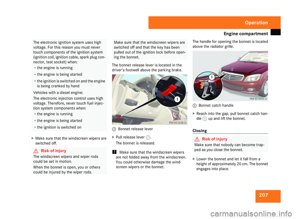
The bonnet release lever is located in the
driver's footwell above the parking brake. 1
Bonnet release lever
X Pull release lever 1.
The bonnet is released.
! Make sure that the windscreen wipers
are not folded away from the windscreen .
You could otherwise damage the wind-
screen wipers or the bonnet. The handle for opening the bonnet is located
above the radiator grille.
1
Bonnet catch handle
X Reach into the gap, pull bonnet catch han -
dle 1up and lift the bonnet.
Closing G
Risk of injury
Make sure that nobody can become trap -
ped as you close the bonnet.
X Lower the bonnet and let it fall from a
height of approximately 20 cm. The bonnet
engages into place. Operation
204_AKB; 2; 3, en-GB
mkalafa,
2007-06-26T23:11:51+02:00 - Seite 207
Page 225 of 377
Trailer towing*
22
2
specification, it is greased or dry (without
grease) when used. Notes on towing a trailer
G
Risk of accident
When reversing the vehicle towards the
trailer, make sure there is nobody between
the trailer and the vehicle.
Couple and uncouple the trailer carefully. If
you do not couple the trailer to the towing
vehicle correctly, the trailer could become
detached .
Make sure that the following values are not
exceeded:
R The permitted trailer drawbar nose-
weight
R The permitted trailer load
R The permitted rear axle load of the towing
vehicle
R The maximum permissible gross vehicle
weight of both the towing vehicle and the
trailer
You will find the applicable permissible val-
ues which must not be exceeded in the
vehicle documents. You will find the values approved by the
manufacturer on the vehicle identification
plates and those for the towing vehicle in
the “Technical data” section.
The maximum permissible trailer drawbar
noseweight on the ball coupling is 75 kg.
However, the weight must not exceed the fig-
ure given on the trailer hitch and trailer iden-
tification plates. The lowest weight applies.
! Use a noseweight as close as possible to
the maximum permissible noseweight. Do
not use a noseweight of less than 50 kg,
otherwise the trailer may come loose.
Bear in mind that the payload and the rear
axle load are reduced by the actual nose-
weight.
i The height of the ball coupling changes
with the load of the vehicle. If necessary,
use a trailer with a height-adjustable draw-
bar.
Coupling up a trailer G
Risk of injury
Do not connect a trailer with an engaged
overrun brake. Otherwise, your hand could become trapped between the bumper and
drawbar.
! Do not uncouple a trailer with overru n
brake between the bumper and drawbar,
otherwise your vehicle could be damaged
by the spring action of the overrun brake.
X Position the trailer level behind the vehicle.
X Couple up the trailer .
X Establish the electrical connectio n
between the vehicle and the trailer.
Driving tip s In Germany, the maximum permitted speed
for vehicle/trailer combinations is 80 km/h.
!
A maximum speed of 80 km/h should not
be exceeded, even in countries where
higher speeds are permitted for vehicle /
trailer combinations.
When towing a trailer, your vehicle's handling
characteristics will be different in compariso n
to when driving without a trailer.
The vehicle/trailer combination:
R is heavier
R is restricted in its acceleration and gradi-
ent-climbing capabilit yOperation
* optional
204_AKB; 2; 3, en-GB
mkalafa,
2007-06-26T23:11:51+02:00 - Seite 222
Page 237 of 377
Where will I find...?
234
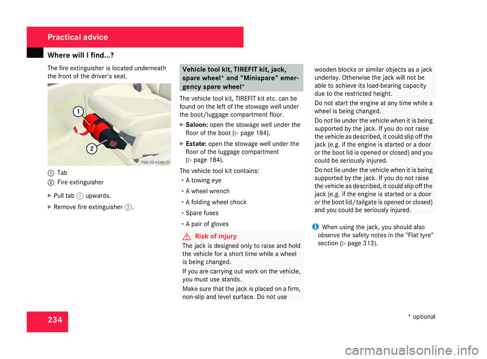
The fire extinguisher is located underneath
the front of the driver's seat.
1
Tab
2 Fire extinguishe r
X Pull tab 1upwards.
X Remove fire extinguisher 2. Vehicle tool kit, TIREFIT kit, jack
,
spare wheel* and "Minispare" emer-
gency spare wheel*
The vehicle tool kit, TIREFIT kit etc. can be
found on the left of the stowage well under
the boot/luggage compartment floor.
X Saloon: open the stowage well under the
floor of the boot (Y page 184).
X Estate: open the stowage well under th e
floor of the luggage compartment
( Y page 184).
The vehicle tool kit contains :
R A towing ey e
R A wheel wrench
R A folding wheel chock
R Spare fuses
R A pair of glove s G
Risk of injury
The jack is designed only to raise and hol d
the vehicle for a short time while a whee l
is being changed.
If you are carrying out work on the vehicle,
you must use stands.
Make sure that the jack is placed on a firm ,
non-slip and level surface. Do not us e wooden blocks or similar objects as a jac
k
underlay. Otherwise the jack will not be
able to achieve its load-bearing capacit y
due to the restricted height.
Do not start the engine at any time while a
wheel is being changed.
Do not lie under the vehicle when it is bein g
supported by the jack. If you do not raise
the vehicle as described, it could slip off the
jack (e.g. if the engine is started or a door
or the boot lid is opened or closed) and you
could be seriously injured.
Do not lie under the vehicle when it is being
supported by the jack. If you do not raise
the vehicle as described, it could slip off the
jack (e.g. if the engine is started or a door
or the boot lid/tailgate is opened or closed)
and you could be seriously injured.
i When using the jack, you should also
observe the safety notes in the "Flat tyre"
section (Y page 313). Practical advice
* optional
204_AKB; 2; 3, en-GB
mkalafa,
2007-06-26T23:11:51+02:00 - Seite 234
Page 317 of 377
Flat tyre
314
Vehicles with automatic transmission
*X
Move the selector lever to P.
For all vehicles X
Place the warning triangle (Y page 232) or
warning lamps at a suitable distance.
Observe legal requirements. G
Risk of injury
The jack is designed only to raise and hol d
the vehicle for a short time while a whee l
is being changed.
If you are carrying out work on the vehicle,
you must use stands.
Make sure that the jack is placed on a firm ,
non-slip and level surface. Do not us e
wooden blocks or similar objects as a jac k
underlay. Otherwise the jack will not be
able to achieve its load-bearing capacit y
due to the restricted height.
Do not start the engine at any time while a
wheel is being changed.
Do not lie under the vehicle when it is bein g
supported by the jack. If you do not raise
the vehicle as described, it could slip off the
jack (e.g. if the engine is started or a door or the boot lid/tailgate is opened or closed)
and you could be seriously injured. Using the TIREFIT kit
You can use the TIREFIT kit to seal small
punctures, particularly those in the tyre tread.
You can use TIREFIT in outdoor temperatures
down to -20 °C. G
Risk of accident
In the following situations, your safety is at
particular risk and TIREFIT is unable to pro -
vide breakdown assistance:
R if there are cuts or punctures in the tyre
greater than 4 mm
R if the wheel rim is damaged
R if you have driven at very low tyre pres-
sures or on a flat tyre
Do not drive any further. Consult a qualified
specialist workshop which has the neces-
sary specialist knowledge and tools to carr y
out the work required.
Mercedes-Benz recommends that you use
a Mercedes-Benz Service Centre for this
purpose. In particular, work relevant to
safety or on safety-related systems must be carried out at a qualified specialist work-
shop.
X Do not remove any foreign objects which
have penetrated the tyre, e.g. screws or
nails .
X Remove TIREFIT, the accompanying "max .
80 km/h“ and the electric air pump from
the stowage compartment in the boot floo r
(Saloon) or the luggage compartment floor
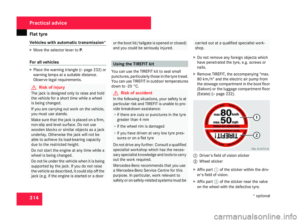
(Estate) (Y page 232). 1
Driver's field of vision sticker
2 Wheel sticker
X Affix part 1of the sticker within the driv-
er's field of vision.
X Affix part 2of the sticker near the valve
on the wheel with the defective tyre. Practical advice
* optional
204_AKB; 2; 3, en-GB
mkalafa,
2007-06-26T23:11:51+02:00 - Seite 314
Page 358 of 377
Vehicle weights
35
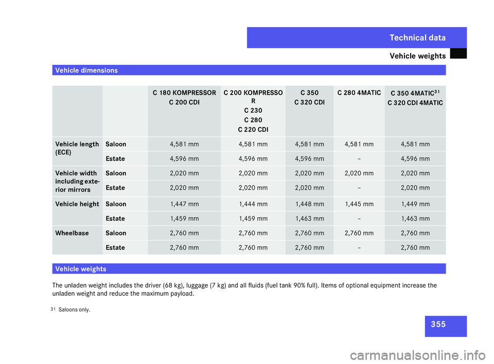
5 Vehicle dimensions
C 180 KOMPRESSO
R
C 200 CDI C 200 KOMPRESSO
R
C 230
C 280
C 220 CDI C 350
C 320 CDI C 280 4MATIC
C 350 4MATIC
31
C 320 CDI 4MATIC Vehicle lengt
h
(ECE) Saloon 4,581 mm 4,581 mm 4,581 mm 4,581 mm 4,581 mm
Estate 4,596 mm 4,596 mm 4,596 mm – 4,596 mm
Vehicle width
including exte
-
rior mirrors Saloo
n 2,020 mm 2,020 mm 2,020 mm 2,020 mm 2,020 mm
Estate 2,020 mm 2,020 mm 2,020 mm – 2,020 mm
Vehicle height Saloon 1,447 mm 1,444 mm 1,448 mm 1,445 mm 1,449 mm
Estate 1,459 mm 1,459 mm 1,463 mm – 1,463 mm
Wheelbas
e Saloon 2,760 mm 2,760 mm 2,760 mm 2,760 mm 2,760 mm
Estate 2,760 mm 2,760 mm 2,760 mm – 2,760 mm
Vehicle weights
The unladen weight includes the driver (68 kg), luggage (7 kg) and all fluids (fuel tank 90% full). Items of optional equipment increase the
unladen weight and reduce the maximum payload.
31 Saloons only . Techni
cal data
204_AKB; 2; 3, en-GB
mkalafa
, 2007-06-26T23:11:51+02:00 - Seite 355