Page 108 of 344

399
Features of your vehicle
SRS careYour Supplemental Restraint System is
virtually maintenance-free. There are no
parts which you can service.
You must have the system serviced
under the following circumstances:
If an air bag ever inflates, the air bagmust be replaced. Do not try to remove
or discard the air bag by yourself. This
must be done by an authorized Kia
dealer.
If the air bag warning indicator light alerts you to a problem, have the air
bag system checked as soon as possi-
ble. Otherwise, your air bag system
may be ineffective.
When repairing or scrapping thevehicles Repairing steering wheel, instrument panel, center console or roofs, or
installing car audio around center con-
sole or painting front metal sheet could
disable the air bag system. Have them
checked by an authorized Kia dealer.
When leaving the vehicle at an autho- rized Kia dealer, inform the facility that
the vehicle is equipped with air bag
system, and leave the owner’s manual
in the vehicle.
Since air bag system contains explo- sive chemical substances, contact an
authorized Kia dealer when scrapping
the vehicle.
WARNING
- No mainte-
nance or repair
Do not modify your steering
wheel, seat or any other part of
the Supplemental Restraint
System. Modification could make
the system inoperable.
Do not work on the system’s com- ponents or wiring. This could
cause the air bags to inflate inad-
vertently, possibly seriously injur-
ing someone. Working on the sys-
tem could also disable the sys-
tem so that the air bags would not
deploy in a collision.
Any work on the SRS system, such as removing, installing,
repairing, or any work on the
steering wheel must be per-
formed by a qualified Kia techni-
cian. Improper handling of the air
bag system may result in serious
personal injury or death.
WARNING
- No modifica-tion
Do not modify any part of the air
bag system. Modification could
make the air bag system ineffective
or could cause unnecessary
deployment.
Page 110 of 344

3 101
Features of your vehicle
Power steeringPower steering uses energy from the
engine to assist you in steering the vehi-
cle. If the engine is off or if the power
steering system becomes inoperative,
the vehicle may still be steered, but it will
require increased steering effort.
Should you notice any change in the
effort required to steer during normal
vehicle operation, have the power steer-
ing checked by an Authorized Kia Dealer.
✽ ✽NOTICEIf the vehicle is parked for extended
periods outside in cold weather (below -
10 °C/14 °F), the power steering may
require increased effort when the engine
is first started. This is caused by
increased fluid viscosity due to the cold
weather and does not indicate a mal-
function.
When this happens, increase the engine
RPM by depressing accelerator until the
RPM reaches 1,500 rpm then release or
let the engine idle for two or three min-
utes to warm up the fluid.
STEERING WHEEL
CAUTION
Never hold the steering wheel
against a stop (extreme right orleft turn) for more than 5 secondswith the engine running. Holding the steering wheel for more than5 seconds in either position maycause damage to the power steer-ing pump.
If the power steering drive belt breaks or if the power steeringpump malfunctions, the steeringeffort will greatly increase.
Page 111 of 344
Features of your vehicle102
3Tilt steering A tilt steering wheel allows you to adjust
the steering wheel before you drive. You
can also raise it to the highest level to
give your legs more room when you exit
and enter the vehicle.
The steering wheel should be positioned
so that it is comfortable for you to drive,
while permitting you to see the instru-
ment panel warning lights and gauges.
To change the steering wheel angle, pull
up the lock release lever (1), adjust the
steering wheel to the desired angle (2),
then release the lock-release lever to
lock the steering wheel in place. Be sure
to adjust the steering wheel to the
desired position before driving.
WARNING
Never adjust the angle of steeringwheel while driving. You may lose
your steering control and cause
severe personal injury or acci-
dents.
After adjusting, push the steering wheel both up and down to be
certain it is locked in position.
OVQ036021N
Page 142 of 344

3 133
Features of your vehicle
Rear window wiper and washer
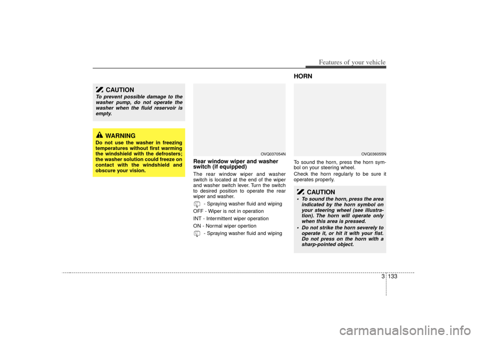
switch (if equipped)The rear window wiper and washer
switch is located at the end of the wiper
and washer switch lever. Turn the switch
to desired position to operate the rear
wiper and washer.- Spraying washer fluid and wiping
OFF - Wiper is not in operation
INT - Intermittent wiper operation
ON - Normal wiper opertion - Spraying washer fluid and wiping
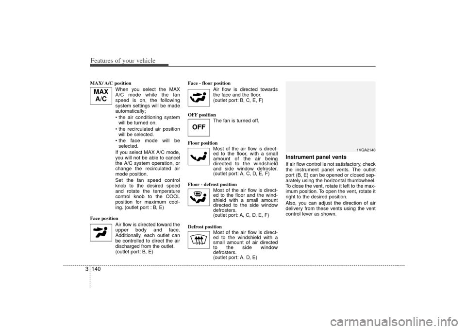
HORNTo sound the horn, press the horn sym-
bol on your steering wheel.
Check the horn regularly to be sure it
operates properly.
CAUTION
To prevent possible damage to thewasher pump, do not operate thewasher when the fluid reservoir isempty.
WARNING
Do not use the washer in freezing
temperatures without first warming
the windshield with the defrosters;
the washer solution could freeze on
contact with the windshield and
obscure your vision.
OVQ037054N
CAUTION
To sound the horn, press the area indicated by the horn symbol onyour steering wheel (see illustra-tion). The horn will operate only when this area is pressed.
Do not strike the horn severely to operate it, or hit it with your fist.Do not press on the horn with asharp-pointed object.
OVQ036055N
Page 149 of 344

Features of your vehicle140
3MAX/ A/C position
When you select the MAX
A/C mode while the fan
speed is on, the following
system settings will be made
automatically;
will be turned on.
will be selected.
selected.
If you select MAX A/C mode, you will not be able to cancel
the A/C system operation, or
change the recirculated air
mode position.
Set the fan speed control knob to the desired speed
and rotate the temperature
control knob to the COOL
position for maximum cool-
ing. (outlet port : B, E)
Face position Air flow is directed toward theupper body and face.
Additionally, each outlet can
be controlled to direct the air
discharged from the outlet.
(outlet port: B, E) Face - floor position
Air flow is directed towardsthe face and the floor.
(outlet port: B, C, E, F)
OFF position The fan is turned off.
Floor position Most of the air flow is direct-ed to the floor, with a small
amount of the air being
directed to the windshield
and side window defroster.
(outlet port: A, C, D, E, F)
Floor - defrost position Most of the air flow is direct-
ed to the floor and the wind-
shield with a small amount
directed to the side window
defrosters.
(outlet port: A, C, D, E, F)
Defrost position Most of the air flow is direct-
ed to the windshield with a
small amount of air directed
to the side window
defrosters.
(outlet port: A, D, E)
Instrument panel ventsIf air flow control is not satisfactory, check
the instrument panel vents. The outlet
port (B, E) can be opened or closed sep-
arately using the horizontal thumbwheel.
To close the vent, rotate it left to the max-
imum position. To open the vent, rotate it
right to the desired position.
Also, you can adjust the direction of air
delivery from these vents using the vent
control lever as shown.
OFF
MAXA/C
1VQA2148
Page 162 of 344

3 153
Features of your vehicle
Face position
Air flow is directed toward theupper body and face.
Additionally, each outlet can
be controlled to direct the air
discharged from the outlet.
(outlet port: B, E)
Face - floor position
Air flow is directed towardsthe face and the floor.
(outlet port: B, C, E, F)
Floor position
Most of the air flow is direct-ed to the floor, with a small
amount of the air being
directed to the windshield
and side window defroster.
(outlet port: A, C, D, E, F)
Floor - defrost position
Most of the air flow is direct-ed to the floor and the wind-
shield with a small amount
directed to the side window
defrosters.
(outlet port:
A, C, D, E, F
)
Instrument panel ventsIf air flow control is not satisfactory, check
the instrument panel vents. The outlet
port (B, E) can be opened or closed sep-
arately using the horizontal thumbwheel.
To close the vent, rotate it left to the max-
imum position. To open the vent, rotate it
right to the desired position.
Also, you can adjust the direction of air
delivery from these vents using the vent
control lever as shown.
Air conditioning button Push the A/C button to turn the air condi-
tioning system on (indicator light will illu-
minate).
Push the button again to turn the air con-
ditioning system off.
1VQA2148
OVQ036077N
Page 178 of 344
3 169
Features of your vehicle
These compartments can be used to
store small items required by the driver
or passengers.
STORAGE COMPARTMENT
CAUTION
To avoid possible theft, do not leavevaluables in the storage compart-ment.
1VQA2197/1VQA2313/1VQA2192/1VQA2314/1VQA2193
WARNING
- Flammable
materials
Do not store cigarette lighters,
propane cylinders, or other flamma-
ble/explosive materials in the vehi-
cle. These items may catch fire
and/or explode if the vehicle is
exposed to hot temperatures for
extended periods.
WARNING
Always keep the storage compart-
ment covers closed while driving.
Do not attempt to place so many
items in the storage compartment
that the storage compartment cover
can not close securely.
Long wheelbase
Page 184 of 344
3 175
Features of your vehicle
RearCups or small beverage cans may be
placed in the cup holders.
Shopping bag holder FrontTo use the holder, push the lower portion.
Rear✽ ✽NOTICEDo not hang heavy bags, since those may
damage the holder.
1VQA2202
CAUTION
Do not hang a bag weighing more
than 3 kg (7 lbs.). It may cause dam- age to the shopping bag holder.
OVQ036090NOVQ027068N
Long wheelbaseShort wheelbase
OVQ036308NOVQ037341N
Long wheelbaseShort wheelbase