2007 ISUZU KB P190 deck
[x] Cancel search: deckPage 980 of 6020

6C – 16 FUEL SYSTEM
FILLER NECK
Removal
1. Remove the fuel tank.
NOTE: Refer to "Fuel Tank" in this section.
2. Put a marking the following point as the filler neck assembl
y
is restored.
• Each joint area of the hose (to restore axial direction and
insertion length of the hose)
• Each fasten area of the clamp (to restore axial direction
and position of the clamp)
• Each bolt in the clamp (to restore fasten length of bolt in
the clamp)
• The band clip (to restore position and fasten length o
f
the band clip)
NOTE: Cover end of each hose and pipe to prevent any dust
entering.
Installation
1. Align each marking and restore the following point.
• Each joint area of the hose (Restore axial direction and
insertion length of the hose)
• Each fasten area of the clamp (Restore axial direction
and position of the clamp)
• Each bolt in the clamp (Restore fasten length of bolt in
the clamp)
Torque N·m (kg·m / lb ft)
2.5 (0.25 / 21.7)
filler neck side except flat deck model.
• The band clip (Restore position and fasten length of the
band clip)
2. Install the fuel tank.
NOTE: Refer to "Fuel Tank" in this section.
BACK TO CHAPTER INDEX
TO MODEL INDEX
ISUZU KB P190 2007
Page 1587 of 6020
6C-46 FUEL SYSTEM (4JK1/4JJ1)
Filler Neck
Removal
1. Remove the fuel tank.
Note: Refer to "Fuel Tank" in this section. 2. Put a marking on the following points as the fille
r
neck assembly is restored.
• Each joint area of the hose (to restore axial
direction and insertion length of the hose)
• Each fasten area of the clamp (to restore axial
direction and position of the clamp)
• Each bolt in the clamp (to restore fasten length
of bolt in the clamp)
• The band clip (to restore position and fasten
length of the band clip)
Note: Cover end of each hose and pipe to prevent an
y
dust entering.
Installation
1. Align each marking and restore the following point. • Each joint area of the hose (Restore axial
direction and insertion length of the hose)
• Each fasten area of the clamp (Restore axial
direction and position of the clamp)
Tightening torque: 2.5 N·m (0.25 kg ⋅
⋅⋅
⋅
m /21.7 lb in)
Filler neck side except flat deck model.
• Each bolt in the clamp (Restore fasten length o
f
bolt in the clamp)
Tightening torque: 2.5 N·m (0.25 kg ⋅
⋅⋅
⋅
m /21.7 lb in)
Filler neck side except flat deck model.
• The band clip (Restore position and fasten
length of the band clip)
2. Install the fuel tank.
Note: Refer to "Fuel Tank" in this section.
BACK TO CHAPTER INDEX
TO MODEL INDEX
ISUZU KB P190 2007
Page 2101 of 6020
ENGINE MECHANICAL (C24SE) 6A-87
Crankshaft, Cylinder Block (continued)
Flywheel
Starter ring gear Before fitting, heat ring gear to 180 °C -
230 °C
Lateral run-out Permissible lateral run-out of installed
starter ring gear to flywheel: 0.5mm
Precision turning Permissible removal of material in clutch disc lining surface area: 0.3mm
In order to achieve the functional
relationship again after removal of material,
the same removal of material must take
place on the fore part of the flywheel
(contact for clutch assembly)
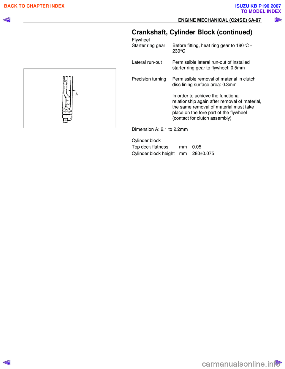
Dimension A: 2.1 to 2.2mm
Cylinder block
Top deck flatness mm 0.05
Cylinder block height mm 280 ±0.075
BACK TO CHAPTER INDEX
TO MODEL INDEX
ISUZU KB P190 2007
Page 2133 of 6020
ENGINE FUEL (C24SE) 6C-15
Filler Neck
Removal
1. Remove the fuel tank.
NOTE: Refer to "Fuel Tank" in this section.
2. Put a marking the following point as the filler neck
assembly is restored.
• Each joint area of the hose (to restore axial
direction and insertion length of the hose)
• Each fasten area of the clamp (to restore axial
direction and position of the clamp)
• Each bolt in the clamp (to restore fasten length
of bolt in the clamp)
• The band clip (to restore position and fasten
length of the band clip)
NOTE: Cover end of each hose and pipe to prevent an
y
dust entering.
Installation
1.
Align each marking and restore the following point.
• Each joint area of the hose (Restore axial
direction and insertion length of the hose)
• Each fasten area of the clamp (Restore axial
direction and position of the clamp)
• Each bolt in the clamp (Restore fasten length o
f
bolt in the clamp)
Torque: 2.5 N ・
・・
・
m (0.25 kg ・
・・
・
m / 2 lb ft) … filler neck
side except flat deck model. • The band clip (Restore position and fasten
length of the band clip)
2. Install the fuel tank.
NOTE: Refer to "Fuel Tank" in this section.
Fuel Gauge Unit
Removal and Installation
As for removal and installation of the Fuel Gauge Unit,
refer to “Fuel Tank" of this section 6C as the fuel gauge
unit is combined with the fuel pump and sende
r
assembly.
BACK TO CHAPTER INDEX
TO MODEL INDEX
ISUZU KB P190 2007
Page 2485 of 6020
Engine Mechanical – V6 Page 6A1–6
Piston Cleaning Procedure............................................................................................................................. 212
Piston Inspection Procedure .................................................................................................... ...................... 213
Piston Measurement ...................................................................................................................................... 213
Piston Ring Measurement ........................................................................................................ ...................... 214
Connecting Rod Cleaning Procedure .............................................................................................. ............... 215
Connecting Rod Visual Inspection Procedure ..................................................................................... ........... 215
Connecting Rod Measurement Procedure ........................................................................................... .......... 216
Reassemble ........................................................................................................................................................ 217
Piston and Piston Pin ..................................................................................................................................... 217
Piston Ring ..................................................................................................................................................... 218
Connecting Rod Bearing ......................................................................................................... ....................... 219
Reinstall .............................................................................................................................................................. 220
Piston Connecting Rod and Connecting Rod Bearing Installation.................................................................. 220
Connecting Rod Bearing Clearance Measurement Procedure....................................................................... 22 1
Connecting Rod Final Assembly Procedure ................................................................................................... 222
4.6 Crankshaft and Main Bearings ......................................................................................................................... 223
Crankshaft End Play Measurement ................................................................................................ .................. 223
Remove ............................................................................................................................................................... 223
Crankshaft Bearing............................................................................................................. ............................ 225
Clean and Inspect .............................................................................................................. ................................ 225
Crankshaft and Main Bearing Cleaning ........................................................................................... ............... 225
Crankshaft and Main Bearing Visual Inspection .................................................................................. ........... 226
Crankshaft Main Bearing Inspection............................................................................................................... 227
Crankshaft Measurement ............................................................................................................................... 228
Reinstall .............................................................................................................................................................. 230
Crankshaft Bearing Installation Procedure ...................................................................................... ............... 230
Crankshaft Main Bearing Clearance Measurement.................................................................................. ...... 231
Crankshaft Final Installation Procedure.......................................................................................................... 233
4.7 Cylinder Block .................................................................................................................................................... 234
Disassemble ....................................................................................................................................................... 234
Clean ................................................................................................................................................................... 238
Inspect ................................................................................................................................................................ 239
Visual Inspection .............................................................................................................. .............................. 239
Measuring Cylinder Bore Diameter ............................................................................................... ................. 239
Measuring Cylinder Bore Taper...................................................................................................................... 239
Measuring Cylinder Bore Out-of-Round ........................................................................................... .............. 239
Deck Flatness Inspection ............................................................................................................................... 240
Reassemble ........................................................................................................................................................ 240
4.8 Thread Repairs ................................................................................................................................................... 244
General Information ............................................................................................................ ............................... 244
General Thread Repair.......................................................................................................... ............................. 246
Main Bearing Cap Bolt Hole Thread Repair ....................................................................................... .............. 251
Cylinder Head Bolt Hole Thread Repair ........................................................................................................... 257
4.9 Thread Repair Specifications............................................................................................................................ 263
Left-hand Cylinder Head Camshaft Cover Face .................................................................................... .......... 263
Left-hand Cylinder Head Front Face ................................................................................................................ 264
Left-hand Cylinder Head Intake Face ............................................................................................................... 265
Left-hand Cylinder Head Exhaust Face........................................................................................... ................. 266
Left-hand Cylinder Head Rear Face ................................................................................................................. 267
Right-hand Cylinder Head Camshaft Cover Face ................................................................................... ........ 268
Right-hand Cylinder Head Front Face.............................................................................................................. 269
Right-hand Cylinder Head Intake Face............................................................................................................. 270
Right-hand Cylinder Head Exhaust Face .......................................................................................... ............... 271
Right-hand Cylinder Head Rear Face ............................................................................................................... 272
Engine Block Front ............................................................................................................................................ 273
Engine Block Left-hand Side .................................................................................................... ........................ 274
Engine Block Right-hand Side ................................................................................................... ....................... 275
Engine Block Rear ............................................................................................................................................. 276
Engine Block Bottom............................................................................................................ ............................. 277
Engine Block Left-hand Deck Face ............................................................................................... ................... 278
BACK TO CHAPTER INDEX
TO MODEL INDEX
ISUZU KB P190 2007
Page 2486 of 6020
Engine Mechanical – V6 Page 6A1–7
Engine Block Right-hand Deck Face................................................................................................................ 279
Engine Front Cover............................................................................................................................................ 280
Upper Intake Manifold Top ...................................................................................................... .......................... 281
Upper Intake Manifold Front .................................................................................................... ......................... 282
Upper Intake Manifold Rear............................................................................................................................... 283
Lower Intake Manifold Top ................................................................................................................................ 284
Oil Pan Front ...................................................................................................................................................... 285
Oil Pan Rear........................................................................................................................................................ 286
Oil Pan Bottom ................................................................................................................. .................................. 287
5 Specifications .....................................................................................................................................288
6 Torque Wrench Specifications................................................................................................... .......292
7 Special Tools ......................................................................................................................................294
BACK TO CHAPTER INDEX
TO MODEL INDEX
ISUZU KB P190 2007
Page 2646 of 6020
Engine Mechanical – V6 Page 6A1–167
Inspect
Visual Inspection
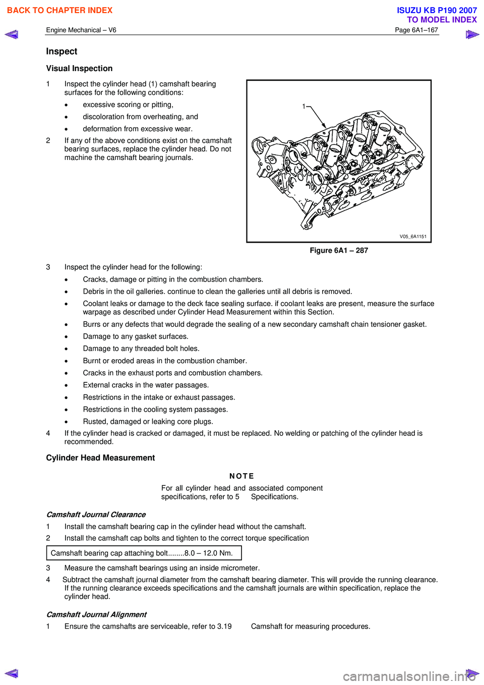
1 Inspect the cylinder head (1) camshaft bearing
surfaces for the following conditions:
• excessive scoring or pitting,
• discoloration from overheating, and
• deformation from excessive wear.
2 If any of the above conditions exist on the camshaft bearing surfaces, replace the cylinder head. Do not
machine the camshaft bearing journals.
Figure 6A1 – 287
3 Inspect the cylinder head for the following: • Cracks, damage or pitting in the combustion chambers.
• Debris in the oil galleries. continue to clean the galleries until all debris is removed.
• Coolant leaks or damage to the deck face sealing surface. if coolant leaks are present, measure the surface
warpage as described under Cylinder Head Measurement within this Section.
• Burrs or any defects that would degrade the sealing of a new secondary camshaft chain tensioner gasket.
• Damage to any gasket surfaces.
• Damage to any threaded bolt holes.
• Burnt or eroded areas in the combustion chamber.
• Cracks in the exhaust ports and combustion chambers.
• External cracks in the water passages.
• Restrictions in the intake or exhaust passages.
• Restrictions in the cooling system passages.
• Rusted, damaged or leaking core plugs.
4 If the cylinder head is cracked or damaged, it must be replaced. No welding or patching of the cylinder head is recommended.
Cylinder Head Measurement
NOTE
For all cylinder head and associated component
specifications, refer to 5 Specifications.
Camshaft Journal Clearance
1 Install the camshaft bearing cap in the cylinder head without the camshaft.
2 Install the camshaft cap bolts and tighten to the correct torque specification
Camshaft bearing cap attaching bolt........8.0 – 12.0 Nm.
3 Measure the camshaft bearings using an inside micrometer.
4 Subtract the camshaft journal diameter from the camshaft bearing diameter. This will provide the running clearance. If the running clearance exceeds specifications and the camshaft journals are within specification, replace the
cylinder head.
Camshaft Journal Alignment
1 Ensure the camshafts are serviceable, refer to 3.19 Camshaft for measuring procedures.
BACK TO CHAPTER INDEX
TO MODEL INDEX
ISUZU KB P190 2007
Page 2647 of 6020
Engine Mechanical – V6 Page 6A1–168
2 Inspect the cylinder head camshaft bearing surfaces for any imperfections or scratches that could inhibit correct
camshaft clearances. Repair minor imperfections or scratches.
3 Install the camshafts in the cylinder head.
4 Install the camshaft bearing caps.
5 Install the camshaft cap bolts and tighten to the correct torque specification.
Camshaft bearing cap attaching bolt........8.0 – 12.0 Nm.
6 Ensure the camshafts spin freely in the cylinder head. If the camshaft does not run freely, replace the cylinder head.
Deck Flatness Inspection
1 Ensure the cylinder head decks are clean and free of gasket material.
2 Inspect the surface for any imperfections or scratches that could inhibit correct cylinder head gasket sealing.
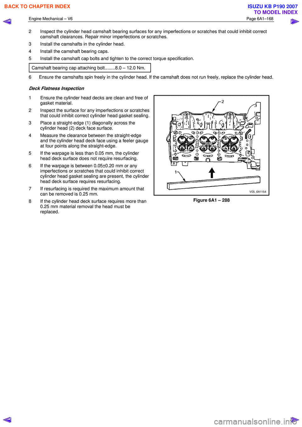
3 Place a straight-edge (1) diagonally across the cylinder head (2) deck face surface.
4 Measure the clearance between the straight-edge and the cylinder head deck face using a feeler gauge
at four points along the straight-edge.
5 If the warpage is less than 0.05 mm, the cylinder head deck surface does not require resurfacing.
6 If the warpage is between 0.05±0.20 mm or any imperfections or scratches that could inhibit correct
cylinder head gasket sealing are present, the cylinder
head deck surface requires resurfacing.
7 If resurfacing is required the maximum amount that can be removed is 0.25 mm.
8 If the cylinder head deck surface requires more than 0.25 mm material removal the head must be
replaced.
Figure 6A1 – 288
BACK TO CHAPTER INDEX
TO MODEL INDEX
ISUZU KB P190 2007