2007 ISUZU KB P190 P0243
[x] Cancel search: P0243Page 1035 of 6020
Engine Control System (4JH1) 6E-1
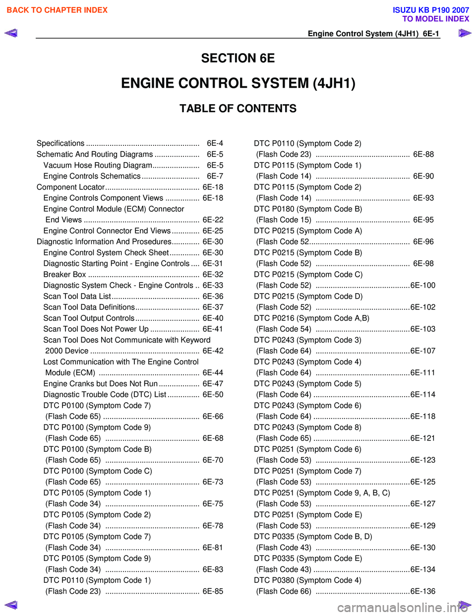
SECTION 6E
ENGINE CONTROL SYSTEM (4JH1)
TABLE OF CONTENTS
Specifications ..................................................... 6E-4
Schematic And Routing Diagrams ..................... 6E-5 Vacuum Hose Routing Diagram...................... 6E-5
Engine Controls Schematics ........................... 6E-7
Component Locator ............................................ 6E-18 Engine Controls Component Views ................ 6E-18
Engine Control Module (ECM) Connector
End Views ...................................................... 6E-22
Engine Control Connector End Views ............. 6E-25
Diagnostic Information And Prosedures............. 6E-30 Engine Control System Check Sheet .............. 6E-30
Diagnostic Starting Point - Engine Controls .... 6E-31
Breaker Box .................................................... 6E-32
Diagnostic System Check - Engine Controls .. 6E-33
Scan Tool Data List ......................................... 6E-36
Scan Tool Data Definitions.............................. 6E-37
Scan Tool Output Controls .............................. 6E-40
Scan Tool Does Not Power Up ....................... 6E-41
Scan Tool Does Not Communicate with Keyword
2000 Device ................................................... 6E-42
Lost Communication with The Engine Control
Module (ECM) ............................................... 6E-44
Engine Cranks but Does Not Run ................... 6E-47
Diagnostic Trouble Code (DTC) List ............... 6E-50
DTC P0100 (Symptom Code 7)
(Flash Code 65) ............................................. 6E-66
DTC P0100 (Symptom Code 9)
(Flash Code 65) ............................................ 6E-68
DTC P0100 (Symptom Code B)
(Flash Code 65) ............................................ 6E-70
DTC P0100 (Symptom Code C)
(Flash Code 65) ............................................ 6E-73
DTC P0105 (Symptom Code 1)
(Flash Code 34) ............................................ 6E-75
DTC P0105 (Symptom Code 2)
(Flash Code 34) ............................................ 6E-78
DTC P0105 (Symptom Code 7)
(Flash Code 34) ............................................ 6E-81
DTC P0105 (Symptom Code 9)
(Flash Code 34) ............................................ 6E-83
DTC P0110 (Symptom Code 1)
(Flash Code 23) ............................................ 6E-85
DTC P0110 (Symptom Code 2)
(Flash Code 23) ............................................ 6E-88
DTC P0115 (Symptom Code 1)
(Flash Code 14) ............................................ 6E-90
DTC P0115 (Symptom Code 2)
(Flash Code 14) ............................................ 6E-93
DTC P0180 (Symptom Code B)
(Flash Code 15) ............................................ 6E-95
DTC P0215 (Symptom Code A)
(Flash Code 52............................................... 6E-96
DTC P0215 (Symptom Code B)
(Flash Code 52) ............................................ 6E-98
DTC P0215 (Symptom Code C)
(Flash Code 52) ............................................ 6E-100
DTC P0215 (Symptom Code D)
(Flash Code 52) ............................................ 6E-102
DTC P0216 (Symptom Code A,B)
(Flash Code 54) ............................................ 6E-103
DTC P0243 (Symptom Code 3)
(Flash Code 64) ............................................ 6E-107
DTC P0243 (Symptom Code 4)
(Flash Code 64) ............................................ 6E-111
DTC P0243 (Symptom Code 5)
(Flash Code 64) ............................................. 6E-114
DTC P0243 (Symptom Code 6)
(Flash Code 64) ............................................. 6E-118
DTC P0243 (Symptom Code 8)
(Flash Code 65) ............................................. 6E-121
DTC P0251 (Symptom Code 6)
(Flash Code 53) ............................................ 6E-123
DTC P0251 (Symptom Code 7)
(Flash Code 53) ............................................ 6E-125
DTC P0251 (Symptom Code 9, A, B, C)
(Flash Code 53) ............................................ 6E-127
DTC P0251 (Symptom Code E)
(Flash Code 53) ............................................ 6E-129
DTC P0335 (Symptom Code B, D)
(Flash Code 43) ............................................ 6E-130
DTC P0335 (Symptom Code E)
(Flash Code 43) ............................................. 6E-134
DTC P0380 (Symptom Code 4)
(Flash Code 66) ............................................ 6E-136
BACK TO CHAPTER INDEX
TO MODEL INDEX
ISUZU KB P190 2007
Page 1087 of 6020
Engine Control System (4JH1) 6E-53
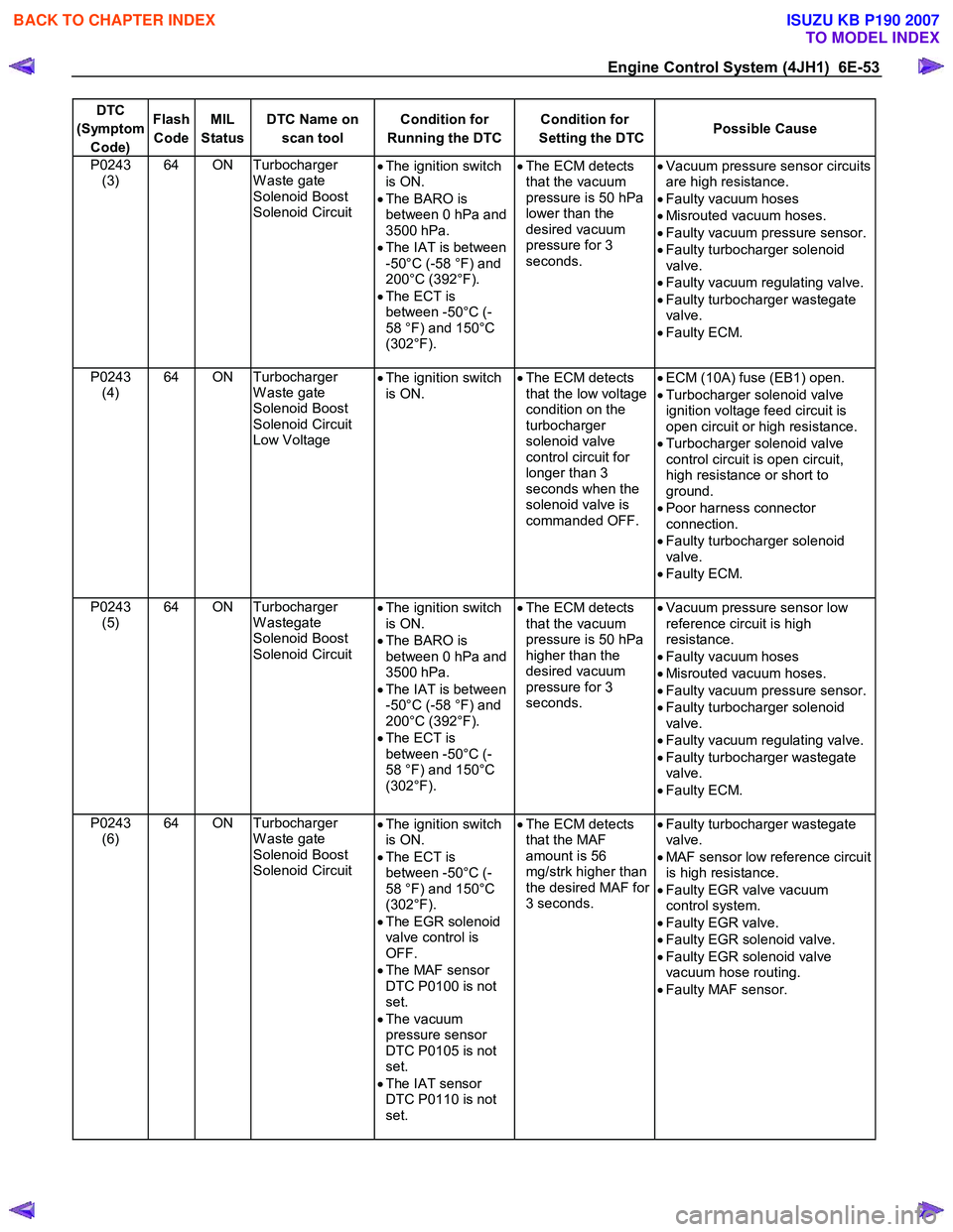
DTC
(Symptom Code) Flash
Code MIL
Status DTC Name on
scan tool Condition for
Running the DTC Condition for
Setting the DTC Possible Cause
P0243
(3) 64 ON Turbocharger
W aste gate
Solenoid Boost
Solenoid Circuit •
The ignition switch
is ON.
• The BARO is
between 0 hPa and
3500 hPa.
• The IAT is between
-50°C (-58 °F) and
200°C (392°F).
• The ECT is
between -50°C (-
58 °F) and 150°C
(302°F).
•
The ECM detects
that the vacuum
pressure is 50 hPa
lower than the
desired vacuum
pressure for 3
seconds.
•
Vacuum pressure sensor circuits
are high resistance.
• Faulty vacuum hoses
• Misrouted vacuum hoses.
• Faulty vacuum pressure sensor.
• Faulty turbocharger solenoid
valve.
• Faulty vacuum regulating valve.
• Faulty turbocharger wastegate
valve.
• Faulty ECM.
P0243 (4) 64 ON Turbocharger
W aste gate
Solenoid Boost
Solenoid Circuit
Low Voltage •
The ignition switch
is ON.
•
The ECM detects
that the low voltage
condition on the
turbocharger
solenoid valve
control circuit for
longer than 3
seconds when the
solenoid valve is
commanded OFF.
•
ECM (10A) fuse (EB1) open.
• Turbocharger solenoid valve
ignition voltage feed circuit is
open circuit or high resistance.
• Turbocharger solenoid valve
control circuit is open circuit,
high resistance or short to
ground.
• Poor harness connector
connection.
• Faulty turbocharger solenoid
valve.
• Faulty ECM.
P0243 (5) 64 ON Turbocharger
W astegate
Solenoid Boost
Solenoid Circuit •
The ignition switch
is ON.
• The BARO is
between 0 hPa and
3500 hPa.
• The IAT is between
-50°C (-58 °F) and
200°C (392°F).
• The ECT is
between -50°C (-
58 °F) and 150°C
(302°F).
•
The ECM detects
that the vacuum
pressure is 50 hPa
higher than the
desired vacuum
pressure for 3
seconds.
•
Vacuum pressure sensor low
reference circuit is high
resistance.
• Faulty vacuum hoses
• Misrouted vacuum hoses.
• Faulty vacuum pressure sensor.
• Faulty turbocharger solenoid
valve.
• Faulty vacuum regulating valve.
• Faulty turbocharger wastegate
valve.
• Faulty ECM.
P0243 (6) 64 ON Turbocharger
W aste gate
Solenoid Boost
Solenoid Circuit •
The ignition switch
is ON.
• The ECT is
between -50°C (-
58 °F) and 150°C
(302°F).
• The EGR solenoid
valve control is
OFF.
• The MAF sensor
DTC P0100 is not
set.
• The vacuum
pressure sensor
DTC P0105 is not
set.
• The IAT sensor
DTC P0110 is not
set.
•
The ECM detects
that the MAF
amount is 56
mg/strk higher than
the desired MAF for
3 seconds.
•
Faulty turbocharger wastegate
valve.
• MAF sensor low reference circuit
is high resistance.
• Faulty EGR valve vacuum
control system.
• Faulty EGR valve.
• Faulty EGR solenoid valve.
• Faulty EGR solenoid valve
vacuum hose routing.
• Faulty MAF sensor.
BACK TO CHAPTER INDEX
TO MODEL INDEX
ISUZU KB P190 2007
Page 1088 of 6020
6E-54 Engine Control System (4JH1)
DTC
(Symptom Code) Flash
Code MIL
Status DTC Name on
scan tool Condition for
Running the DTC Condition for
Setting the DTC Possible Cause
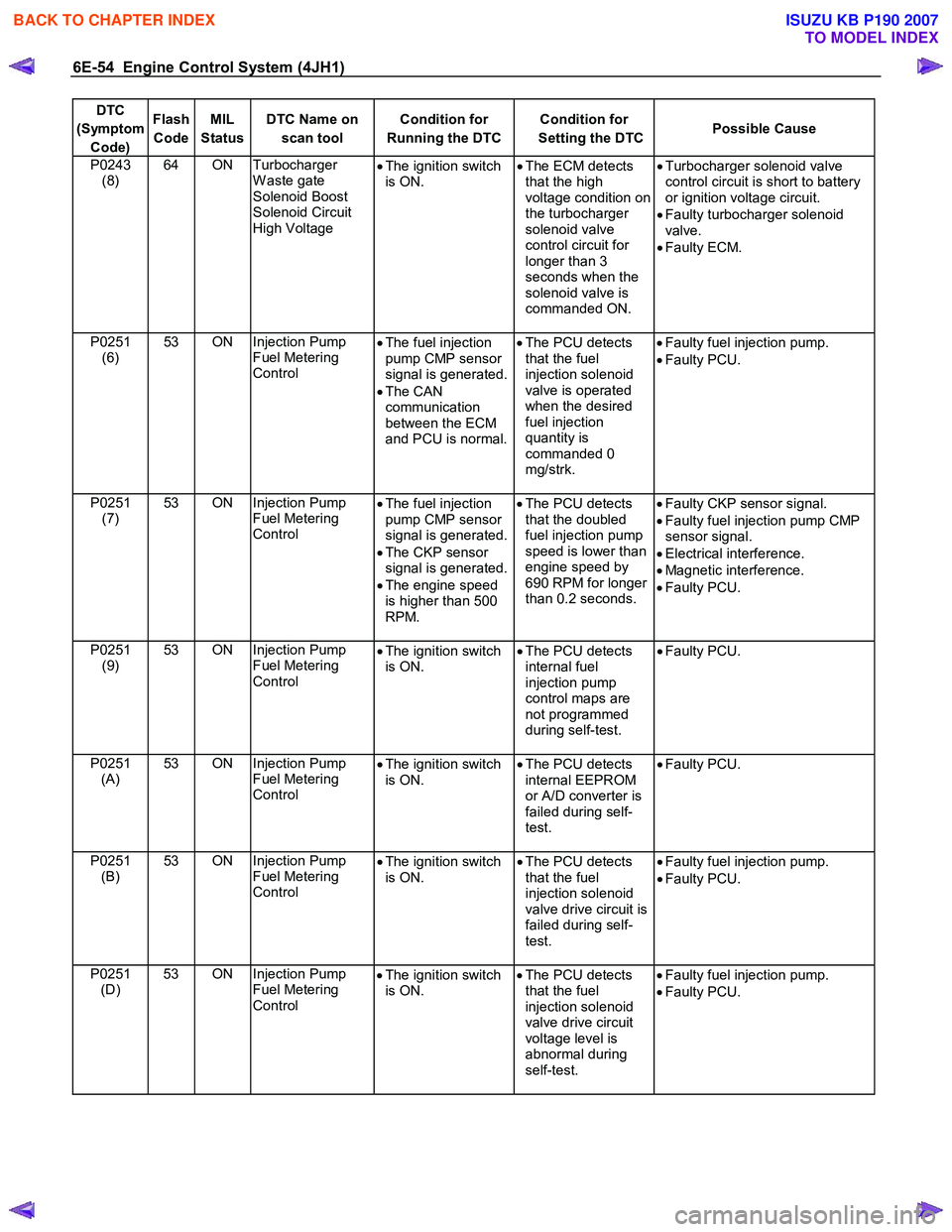
P0243
(8) 64 ON Turbocharger
W aste gate
Solenoid Boost
Solenoid Circuit
High Voltage •
The ignition switch
is ON. •
The ECM detects
that the high
voltage condition on
the turbocharger
solenoid valve
control circuit for
longer than 3
seconds when the
solenoid valve is
commanded ON.
•
Turbocharger solenoid valve
control circuit is short to battery
or ignition voltage circuit.
• Faulty turbocharger solenoid
valve.
• Faulty ECM.
P0251 (6) 53 ON Injection Pump
Fuel Metering
Control •
The fuel injection
pump CMP sensor
signal is generated.
• The CAN
communication
between the ECM
and PCU is normal.
•
The PCU detects
that the fuel
injection solenoid
valve is operated
when the desired
fuel injection
quantity is
commanded 0
mg/strk.
•
Faulty fuel injection pump.
• Faulty PCU.
P0251 (7) 53 ON Injection Pump
Fuel Metering
Control •
The fuel injection
pump CMP sensor
signal is generated.
• The CKP sensor
signal is generated.
• The engine speed
is higher than 500
RPM.
•
The PCU detects
that the doubled
fuel injection pump
speed is lower than
engine speed by
690 RPM for longer
than 0.2 seconds.
•
Faulty CKP sensor signal.
• Faulty fuel injection pump CMP
sensor signal.
• Electrical interference.
• Magnetic interference.
• Faulty PCU.
P0251 (9) 53 ON Injection Pump
Fuel Metering
Control •
The ignition switch
is ON. •
The PCU detects
internal fuel
injection pump
control maps are
not programmed
during self-test.
•
Faulty PCU.
P0251 (A) 53 ON Injection Pump
Fuel Metering
Control •
The ignition switch
is ON. •
The PCU detects
internal EEPROM
or A/D converter is
failed during self-
test.
•
Faulty PCU.
P0251 (B) 53 ON Injection Pump
Fuel Metering
Control •
The ignition switch
is ON. •
The PCU detects
that the fuel
injection solenoid
valve drive circuit is
failed during self-
test.
•
Faulty fuel injection pump.
• Faulty PCU.
P0251 (D) 53 ON Injection Pump
Fuel Metering
Control •
The ignition switch
is ON. •
The PCU detects
that the fuel
injection solenoid
valve drive circuit
voltage level is
abnormal during
self-test.
•
Faulty fuel injection pump.
• Faulty PCU.
BACK TO CHAPTER INDEX
TO MODEL INDEX
ISUZU KB P190 2007
Page 1141 of 6020
Engine Control System (4JH1) 6E-107
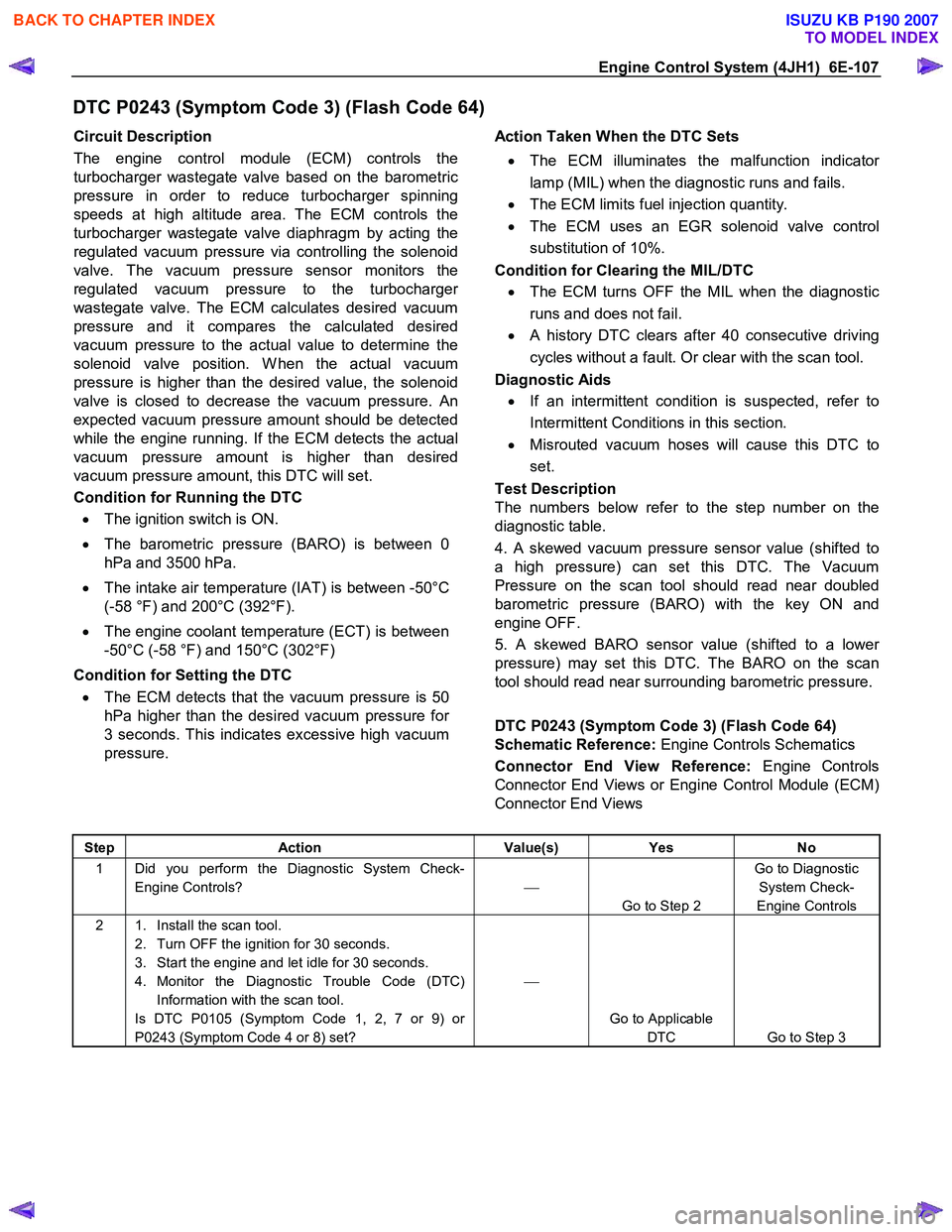
DTC P0243 (Symptom Code 3) (Flash Code 64)
Circuit Description
The engine control module (ECM) controls the
turbocharger wastegate valve based on the barometric
pressure in order to reduce turbocharger spinning
speeds at high altitude area. The ECM controls the
turbocharger wastegate valve diaphragm by acting the
regulated vacuum pressure via controlling the solenoid
valve. The vacuum pressure sensor monitors the
regulated vacuum pressure to the turbocharge
r
wastegate valve. The ECM calculates desired vacuum
pressure and it compares the calculated desired
vacuum pressure to the actual value to determine the
solenoid valve position. W hen the actual vacuum
pressure is higher than the desired value, the solenoid
valve is closed to decrease the vacuum pressure. An
expected vacuum pressure amount should be detected
while the engine running. If the ECM detects the actual
vacuum pressure amount is higher than desired
vacuum pressure amount, this DTC will set.
Condition for Running the DTC
• The ignition switch is ON.
• The barometric pressure (BARO) is between 0
hPa and 3500 hPa.
• The intake air temperature (IAT) is between -50°C
(-58 °F) and 200°C (392°F).
• The engine coolant temperature (ECT) is between
-50°C (-58 °F) and 150°C (302°F)
Condition for Setting the DTC
• The ECM detects that the vacuum pressure is 50
hPa higher than the desired vacuum pressure for
3 seconds. This indicates excessive high vacuum
pressure.
Action Taken When the DTC Sets
• The ECM illuminates the malfunction indicato
r
lamp (MIL) when the diagnostic runs and fails.
• The ECM limits fuel injection quantity.
• The ECM uses an EGR solenoid valve control
substitution of 10%.
Condition for Clearing the MIL/DTC
• The ECM turns OFF the MIL when the diagnostic
runs and does not fail.
• A history DTC clears after 40 consecutive driving
cycles without a fault. Or clear with the scan tool.
Diagnostic Aids
• If an intermittent condition is suspected, refer to
Intermittent Conditions in this section.
• Misrouted vacuum hoses will cause this DTC to
set.
Test Description
The numbers below refer to the step number on the
diagnostic table.
4. A skewed vacuum pressure sensor value (shifted to
a high pressure) can set this DTC. The Vacuum
Pressure on the scan tool should read near doubled
barometric pressure (BARO) with the key ON and
engine OFF.
5. A skewed BARO sensor value (shifted to a lowe
r
pressure) may set this DTC. The BARO on the scan
tool should read near surrounding barometric pressure.
DTC P0243 (Symptom Code 3) (Flash Code 64)
Schematic Reference: Engine Controls Schematics
Connector End View Reference: Engine Controls
Connector End Views or Engine Control Module (ECM)
Connector End Views
Step Action Value(s) Yes No
1 Did you perform the Diagnostic System Check-
Engine Controls?
Go to Step 2 Go to Diagnostic
System Check-
Engine Controls
2 1. Install the scan tool. 2. Turn OFF the ignition for 30 seconds.
3. Start the engine and let idle for 30 seconds.
4. Monitor the Diagnostic Trouble Code (DTC) Information with the scan tool.
Is DTC P0105 (Symptom Code 1, 2, 7 or 9) or
P0243 (Symptom Code 4 or 8) set?
Go to Applicable DTC Go to Step 3
BACK TO CHAPTER INDEX
TO MODEL INDEX
ISUZU KB P190 2007
Page 1145 of 6020
Engine Control System (4JH1) 6E-111
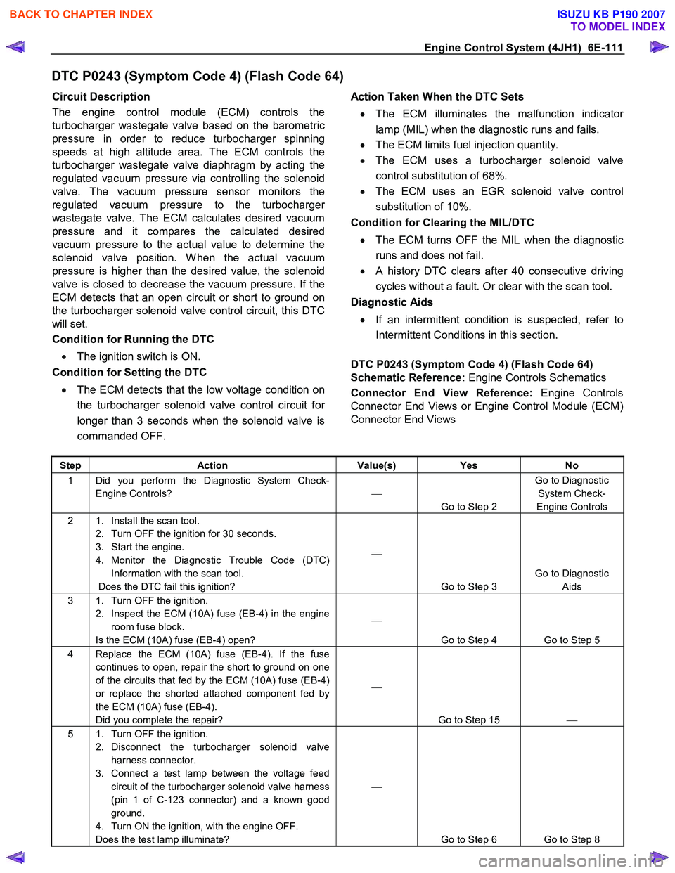
DTC P0243 (Symptom Code 4) (Flash Code 64)
Circuit Description
The engine control module (ECM) controls the
turbocharger wastegate valve based on the barometric
pressure in order to reduce turbocharger spinning
speeds at high altitude area. The ECM controls the
turbocharger wastegate valve diaphragm by acting the
regulated vacuum pressure via controlling the solenoid
valve. The vacuum pressure sensor monitors the
regulated vacuum pressure to the turbocharge
r
wastegate valve. The ECM calculates desired vacuum
pressure and it compares the calculated desired
vacuum pressure to the actual value to determine the
solenoid valve position. W hen the actual vacuum
pressure is higher than the desired value, the solenoid
valve is closed to decrease the vacuum pressure. If the
ECM detects that an open circuit or short to ground on
the turbocharger solenoid valve control circuit, this DTC
will set.
Condition for Running the DTC
• The ignition switch is ON.
Condition for Setting the DTC
• The ECM detects that the low voltage condition on
the turbocharger solenoid valve control circuit fo
r
longer than 3 seconds when the solenoid valve is
commanded OFF.
Action Taken When the DTC Sets
• The ECM illuminates the malfunction indicato
r
lamp (MIL) when the diagnostic runs and fails.
• The ECM limits fuel injection quantity.
• The ECM uses a turbocharger solenoid valve
control substitution of 68%.
• The ECM uses an EGR solenoid valve control
substitution of 10%.
Condition for Clearing the MIL/DTC
• The ECM turns OFF the MIL when the diagnostic
runs and does not fail.
• A history DTC clears after 40 consecutive driving
cycles without a fault. Or clear with the scan tool.
Diagnostic Aids
• If an intermittent condition is suspected, refer to
Intermittent Conditions in this section.
DTC P0243 (Symptom Code 4) (Flash Code 64)
Schematic Reference: Engine Controls Schematics
Connector End View Reference: Engine Controls
Connector End Views or Engine Control Module (ECM)
Connector End Views
Step Action Value(s) Yes No
1 Did you perform the Diagnostic System Check-
Engine Controls?
Go to Step 2 Go to Diagnostic
System Check-
Engine Controls
2 1. Install the scan tool. 2. Turn OFF the ignition for 30 seconds.
3. Start the engine.
4. Monitor the Diagnostic Trouble Code (DTC) Information with the scan tool.
Does the DTC fail this ignition?
Go to Step 3 Go to Diagnostic
Aids
3 1. Turn OFF the ignition. 2. Inspect the ECM (10A) fuse (EB-4) in the engine room fuse block.
Is the ECM (10A) fuse (EB-4) open?
Go to Step 4 Go to Step 5
4 Replace the ECM (10A) fuse (EB-4). If the fuse continues to open, repair the short to ground on one
of the circuits that fed by the ECM (10A) fuse (EB-4)
or replace the shorted attached component fed by
the ECM (10A) fuse (EB-4).
Did you complete the repair?
Go to Step 15
5 1. Turn OFF the ignition.
2. Disconnect the turbocharger solenoid valve harness connector.
3. Connect a test lamp between the voltage feed circuit of the turbocharger solenoid valve harness
(pin 1 of C-123 connector) and a known good
ground.
4. Turn ON the ignition, with the engine OFF.
Does the test lamp illuminate?
Go to Step 6 Go to Step 8
BACK TO CHAPTER INDEX
TO MODEL INDEX
ISUZU KB P190 2007
Page 1148 of 6020
6E-114 Engine Control System (4JH1)
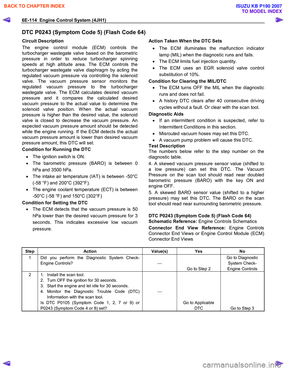
DTC P0243 (Symptom Code 5) (Flash Code 64)
Circuit Description
The engine control module (ECM) controls the
turbocharger wastegate valve based on the barometric
pressure in order to reduce turbocharger spinning
speeds at high altitude area. The ECM controls the
turbocharger wastegate valve diaphragm by acting the
regulated vacuum pressure via controlling the solenoid
valve. The vacuum pressure sensor monitors the
regulated vacuum pressure to the turbocharge
r
wastegate valve. The ECM calculates desired vacuum
pressure and it compares the calculated desired
vacuum pressure to the actual value to determine the
solenoid valve position. W hen the actual vacuum
pressure is higher than the desired value, the solenoid
valve is closed to decrease the vacuum pressure. An
expected vacuum pressure amount should be detected
while the engine running. If the ECM detects the actual
vacuum pressure amount is lower than desired vacuum
pressure amount, this DTC will set.
Condition for Running the DTC
• The ignition switch is ON.
• The barometric pressure (BARO) is between 0
hPa and 3500 hPa.
• The intake air temperature (IAT) is between -50°C
(-58 °F) and 200°C (392°F).
• The engine coolant temperature (ECT) is between
-50°C (-58 °F) and 150°C (302°F)
Condition for Setting the DTC
• The ECM detects that the vacuum pressure is 50
hPa lower than the desired vacuum pressure for 3
seconds. This indicates excessive low vacuum
pressure.
Action Taken When the DTC Sets
• The ECM illuminates the malfunction indicato
r
lamp (MIL) when the diagnostic runs and fails.
• The ECM limits fuel injection quantity.
• The ECM uses an EGR solenoid valve control
substitution of 10%.
Condition for Clearing the MIL/DTC
• The ECM turns OFF the MIL when the diagnostic
runs and does not fail.
• A history DTC clears after 40 consecutive driving
cycles without a fault. Or clear with the scan tool.
Diagnostic Aids
• If an intermittent condition is suspected, refer to
Intermittent Conditions in this section.
• Misrouted vacuum hoses may set this DTC.
• A vacuum pump problem will cause this DTC.
Test Description
The numbers below refer to the step number on the
diagnostic table.
4. A skewed vacuum pressure sensor value (shifted to
a low pressure) can set this DTC. The Vacuum
Pressure on the scan tool should read near doubled
barometric pressure (BARO) with the key ON and
engine OFF.
5. A skewed BARO sensor value (shifted to a highe
r
pressure) may set this DTC. The BARO on the scan
tool should read near surrounding barometric pressure.
DTC P0243 (Symptom Code 5) (Flash Code 64)
Schematic Reference: Engine Controls Schematics
Connector End View Reference: Engine Controls
Connector End Views or Engine Control Module (ECM)
Connector End Views
Step Action Value(s) Yes No
1 Did you perform the Diagnostic System Check-
Engine Controls?
Go to Step 2 Go to Diagnostic
System Check-
Engine Controls
2 1. Install the scan tool. 2. Turn OFF the ignition for 30 seconds.
3. Start the engine and let idle for 30 seconds.
4. Monitor the Diagnostic Trouble Code (DTC) Information with the scan tool.
Is DTC P0105 (Symptom Code 1, 2, 7 or 9) or
P0243 (Symptom Code 4 or 8) set?
Go to Applicable DTC Go to Step 3
BACK TO CHAPTER INDEX
TO MODEL INDEX
ISUZU KB P190 2007
Page 1152 of 6020
6E-118 Engine Control System (4JH1)
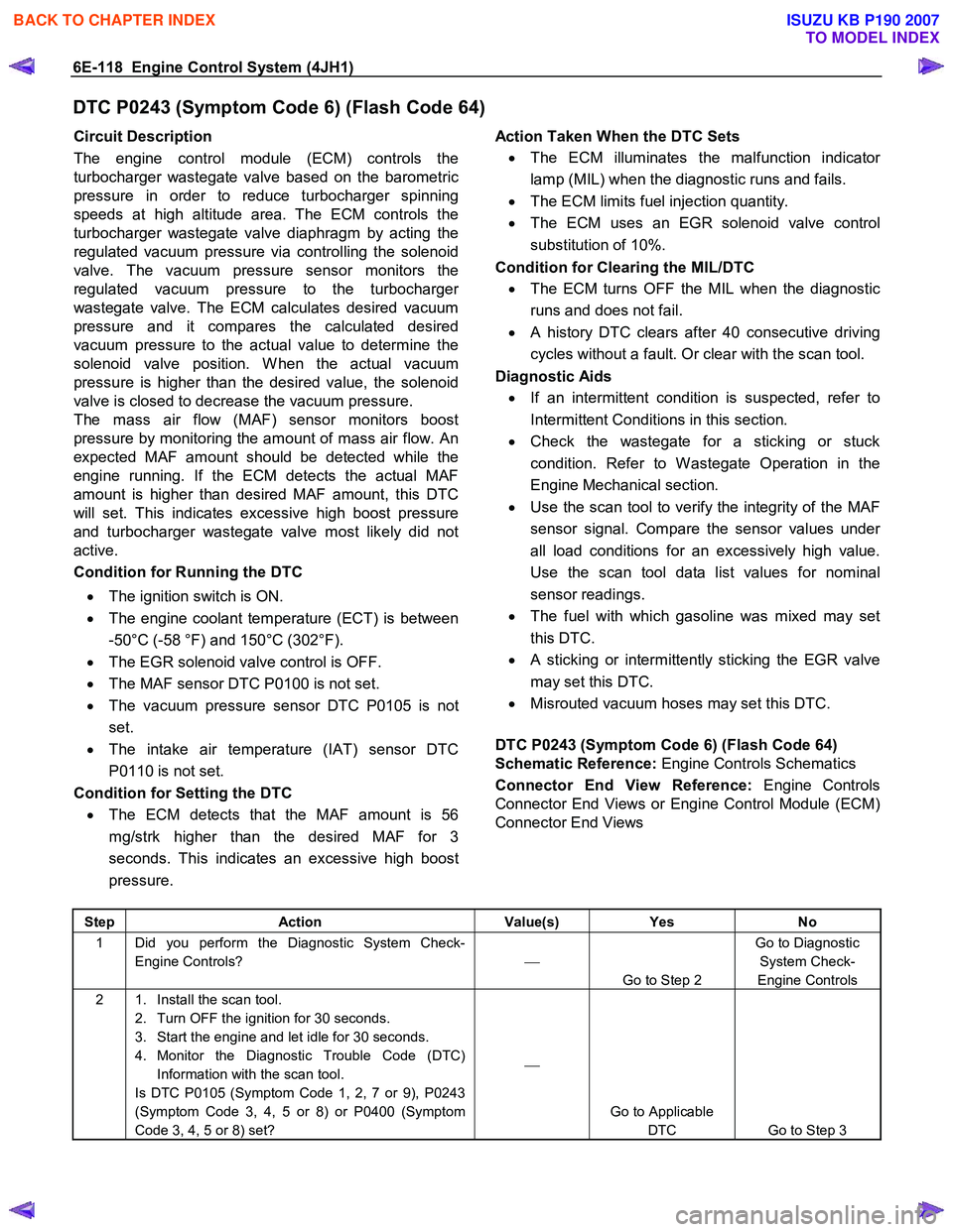
DTC P0243 (Symptom Code 6) (Flash Code 64)
Circuit Description
The engine control module (ECM) controls the
turbocharger wastegate valve based on the barometric
pressure in order to reduce turbocharger spinning
speeds at high altitude area. The ECM controls the
turbocharger wastegate valve diaphragm by acting the
regulated vacuum pressure via controlling the solenoid
valve. The vacuum pressure sensor monitors the
regulated vacuum pressure to the turbocharge
r
wastegate valve. The ECM calculates desired vacuum
pressure and it compares the calculated desired
vacuum pressure to the actual value to determine the
solenoid valve position. W hen the actual vacuum
pressure is higher than the desired value, the solenoid
valve is closed to decrease the vacuum pressure.
The mass air flow (MAF) sensor monitors boost
pressure by monitoring the amount of mass air flow. An
expected MAF amount should be detected while the
engine running. If the ECM detects the actual MAF
amount is higher than desired MAF amount, this DTC
will set. This indicates excessive high boost pressure
and turbocharger wastegate valve most likely did not
active.
Condition for Running the DTC
• The ignition switch is ON.
• The engine coolant temperature (ECT) is between
-50°C (-58 °F) and 150°C (302°F).
• The EGR solenoid valve control is OFF.
• The MAF sensor DTC P0100 is not set.
• The vacuum pressure sensor DTC P0105 is not
set.
• The intake air temperature (IAT) sensor DTC
P0110 is not set.
Condition for Setting the DTC
• The ECM detects that the MAF amount is 56
mg/strk higher than the desired MAF for 3
seconds. This indicates an excessive high boost
pressure.
Action Taken When the DTC Sets
• The ECM illuminates the malfunction indicato
r
lamp (MIL) when the diagnostic runs and fails.
• The ECM limits fuel injection quantity.
• The ECM uses an EGR solenoid valve control
substitution of 10%.
Condition for Clearing the MIL/DTC
• The ECM turns OFF the MIL when the diagnostic
runs and does not fail.
• A history DTC clears after 40 consecutive driving
cycles without a fault. Or clear with the scan tool.
Diagnostic Aids
• If an intermittent condition is suspected, refer to
Intermittent Conditions in this section.
• Check the wastegate for a sticking or stuck
condition. Refer to W astegate Operation in the
Engine Mechanical section.
• Use the scan tool to verify the integrity of the MAF
sensor signal. Compare the sensor values unde
r
all load conditions for an excessively high value.
Use the scan tool data list values for nominal
sensor readings.
• The fuel with which gasoline was mixed may set
this DTC.
• A sticking or intermittently sticking the EGR valve
may set this DTC.
• Misrouted vacuum hoses may set this DTC.
DTC P0243 (Symptom Code 6) (Flash Code 64)
Schematic Reference: Engine Controls Schematics
Connector End View Reference: Engine Controls
Connector End Views or Engine Control Module (ECM)
Connector End Views
Step Action Value(s) Yes No
1 Did you perform the Diagnostic System Check-
Engine Controls?
Go to Step 2 Go to Diagnostic
System Check-
Engine Controls
2 1. Install the scan tool. 2. Turn OFF the ignition for 30 seconds.
3. Start the engine and let idle for 30 seconds.
4. Monitor the Diagnostic Trouble Code (DTC) Information with the scan tool.
Is DTC P0105 (Symptom Code 1, 2, 7 or 9), P0243
(Symptom Code 3, 4, 5 or 8) or P0400 (Symptom
Code 3, 4, 5 or 8) set?
Go to Applicable DTC Go to Step 3
BACK TO CHAPTER INDEX
TO MODEL INDEX
ISUZU KB P190 2007
Page 1155 of 6020
Engine Control System (4JH1) 6E-121
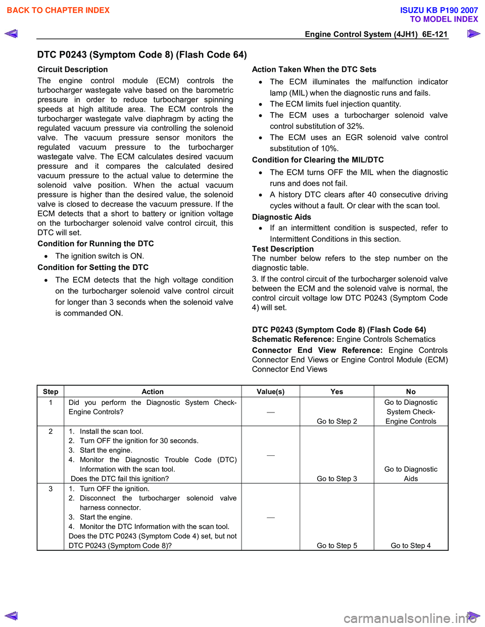
DTC P0243 (Symptom Code 8) (Flash Code 64)
Circuit Description
The engine control module (ECM) controls the
turbocharger wastegate valve based on the barometric
pressure in order to reduce turbocharger spinning
speeds at high altitude area. The ECM controls the
turbocharger wastegate valve diaphragm by acting the
regulated vacuum pressure via controlling the solenoid
valve. The vacuum pressure sensor monitors the
regulated vacuum pressure to the turbocharge
r
wastegate valve. The ECM calculates desired vacuum
pressure and it compares the calculated desired
vacuum pressure to the actual value to determine the
solenoid valve position. W hen the actual vacuum
pressure is higher than the desired value, the solenoid
valve is closed to decrease the vacuum pressure. If the
ECM detects that a short to battery or ignition voltage
on the turbocharger solenoid valve control circuit, this
DTC will set.
Condition for Running the DTC
• The ignition switch is ON.
Condition for Setting the DTC
• The ECM detects that the high voltage condition
on the turbocharger solenoid valve control circuit
for longer than 3 seconds when the solenoid valve
is commanded ON.
Action Taken When the DTC Sets
• The ECM illuminates the malfunction indicato
r
lamp (MIL) when the diagnostic runs and fails.
• The ECM limits fuel injection quantity.
• The ECM uses a turbocharger solenoid valve
control substitution of 32%.
• The ECM uses an EGR solenoid valve control
substitution of 10%.
Condition for Clearing the MIL/DTC
• The ECM turns OFF the MIL when the diagnostic
runs and does not fail.
• A history DTC clears after 40 consecutive driving
cycles without a fault. Or clear with the scan tool.
Diagnostic Aids
• If an intermittent condition is suspected, refer to
Intermittent Conditions in this section.
Test Description
The number below refers to the step number on the
diagnostic table.
3. If the control circuit of the turbocharger solenoid valve
between the ECM and the solenoid valve is normal, the
control circuit voltage low DTC P0243 (Symptom Code
4) will set.
DTC P0243 (Symptom Code 8) (Flash Code 64)
Schematic Reference: Engine Controls Schematics
Connector End View Reference: Engine Controls
Connector End Views or Engine Control Module (ECM)
Connector End Views
Step Action Value(s) Yes No
1 Did you perform the Diagnostic System Check-
Engine Controls?
Go to Step 2 Go to Diagnostic
System Check-
Engine Controls
2 1. Install the scan tool. 2. Turn OFF the ignition for 30 seconds.
3. Start the engine.
4. Monitor the Diagnostic Trouble Code (DTC) Information with the scan tool.
Does the DTC fail this ignition?
Go to Step 3 Go to Diagnostic
Aids
3 1. Turn OFF the ignition. 2. Disconnect the turbocharger solenoid valve harness connector.
3. Start the engine.
4. Monitor the DTC Information with the scan tool.
Does the DTC P0243 (Symptom Code 4) set, but not
DTC P0243 (Symptom Code 8)?
Go to Step 5 Go to Step 4
BACK TO CHAPTER INDEX
TO MODEL INDEX
ISUZU KB P190 2007