2007 ISUZU KB P190 Circuit
[x] Cancel search: CircuitPage 1015 of 6020
6D – 14 ENGINE ELECTRICAL
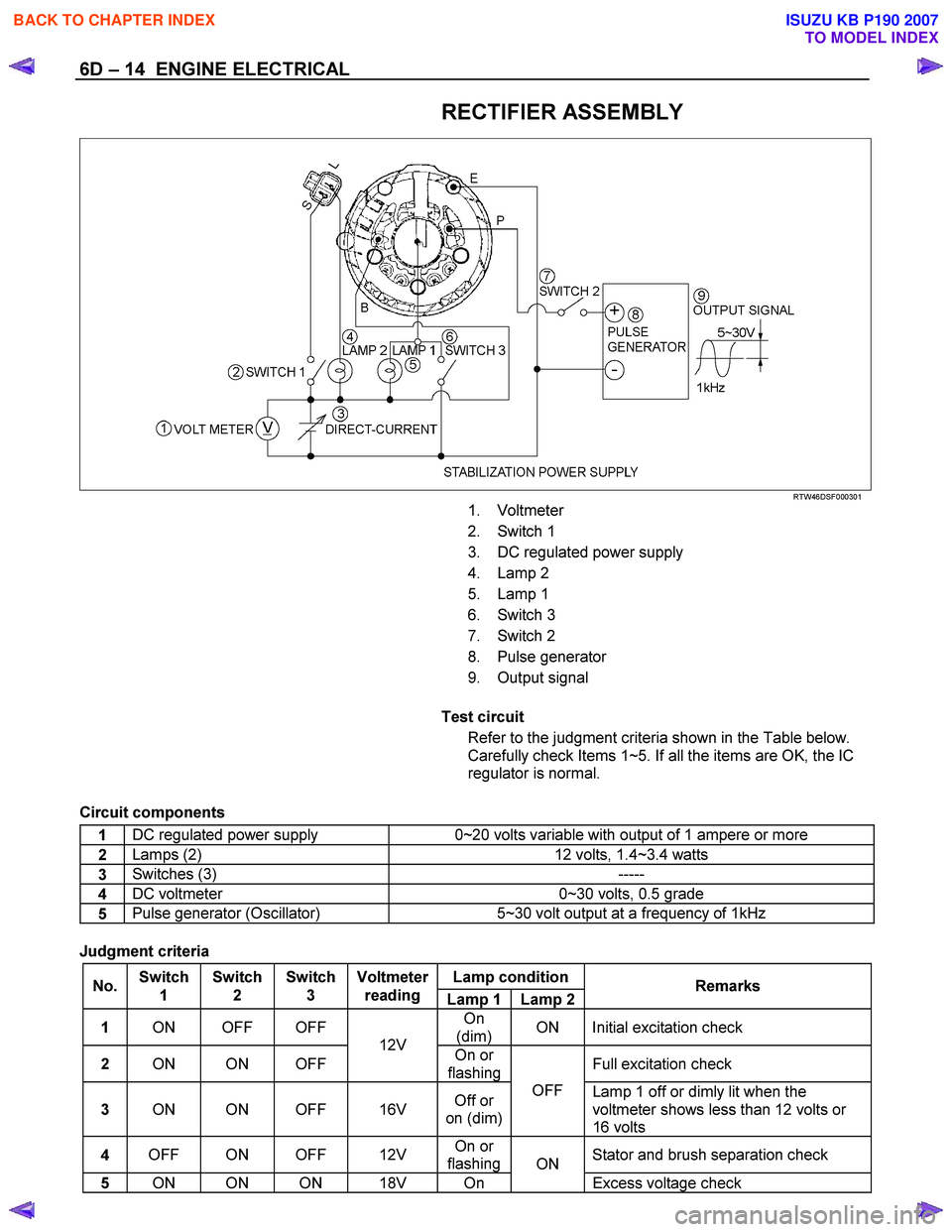
RECTIFIER ASSEMBLY
RTW46DSF000301
1. Voltmeter
2. Switch 1
3. DC regulated power supply
4. Lamp 2
5. Lamp 1
6. Switch 3
7. Switch 2
8. Pulse generator
9. Output signal
Test circuit
Refer to the judgment criteria shown in the Table below.
Carefully check Items 1~5. If all the items are OK, the IC
regulator is normal.
Circuit components
1 DC regulated power supply 0~20 volts variable with output of 1 ampere or more
2 Lamps (2)
12 volts, 1.4~3.4 watts
3 Switches (3)
-----
4 DC voltmeter
0~30 volts, 0.5 grade
5 Pulse generator (Oscillator)
5~30 volt output at a frequency of 1kHz
Judgment criteria
Lamp condition
No. Switch
1 Switch
2 Switch
3 Voltmeter
reading Lamp 1 Lamp 2 Remarks
1
ON OFF OFF On
(dim) ON Initial excitation check
2
ON ON OFF 12V
On or
flashing Full excitation check
3
ON ON OFF 16V Off or
on (dim) OFF
Lamp 1 off or dimly lit when the
voltmeter shows less than 12 volts or
16 volts
4 OFF ON OFF 12V On or
flashing Stator and brush separation check
5
ON ON ON 18V On ON
Excess voltage check
BACK TO CHAPTER INDEX
TO MODEL INDEX
ISUZU KB P190 2007
Page 1027 of 6020
6D – 26 ENGINE ELECTRICAL
INSPECTION AND REPAIR
Make the necessary adjustments, repairs, and part replacement if excessive wear or damage is discovered during
inspection.
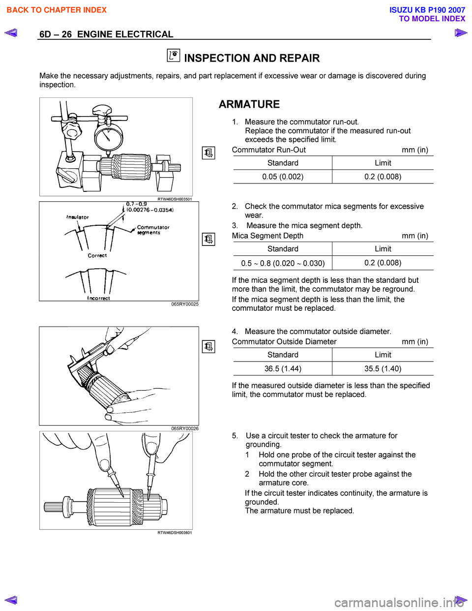
ARMATURE
1. Measure the commutator run-out. Replace the commutator if the measured run-out
exceeds the specified limit.
Commutator Run-Out mm (in)
Standard Limit
0.05 (0.002) 0.2 (0.008)
RTW46DSH003501
2. Check the commutator mica segments for excessive
wear.
3. Measure the mica segment depth.
Mica Segment Depth mm (in)
Standard Limit
0.5 ∼ 0.8 (0.020 ∼ 0.030) 0.2 (0.008)
065RY00025
If the mica segment depth is less than the standard but
more than the limit, the commutator may be reground.
If the mica segment depth is less than the limit, the
commutator must be replaced.
4. Measure the commutator outside diameter.
Commutator Outside Diameter mm (in)
Standard Limit
36.5 (1.44) 35.5 (1.40)
If the measured outside diameter is less than the specified
limit, the commutator must be replaced.
065RY00026
RTW46DSH003601
5. Use a circuit tester to check the armature for
grounding.
1 Hold one probe of the circuit tester against the commutator segment.
2 Hold the other circuit tester probe against the armature core.
If the circuit tester indicates continuity, the armature is grounded.
The armature must be replaced.
BACK TO CHAPTER INDEX
TO MODEL INDEX
ISUZU KB P190 2007
Page 1028 of 6020
ENGINE ELECTRICAL 6D – 27
RTW46DSH003701
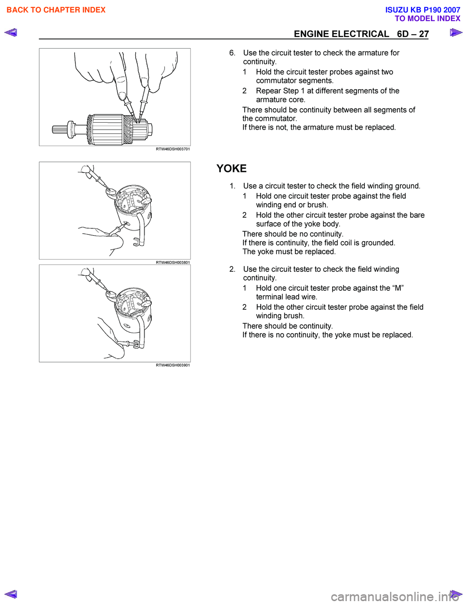
6. Use the circuit tester to check the armature for
continuity.
1 Hold the circuit tester probes against two commutator segments.
2 Repear Step 1 at different segments of the armature core.
There should be continuity between all segments of the commutator.
If there is not, the armature must be replaced.
RTW46DSH003801
YOKE
1. Use a circuit tester to check the field winding ground.
1 Hold one circuit tester probe against the field winding end or brush.
2 Hold the other circuit tester probe against the bare surface of the yoke body.
There should be no continuity. If there is continuity, the field coil is grounded.
The yoke must be replaced.
RTW46DSH003901
2. Use the circuit tester to check the field winding
continuity.
1 Hold one circuit tester probe against the “M ”
terminal lead wire.
2 Hold the other circuit tester probe against the field winding brush.
There should be continuity. If there is no continuity, the yoke must be replaced.
BACK TO CHAPTER INDEX
TO MODEL INDEX
ISUZU KB P190 2007
Page 1029 of 6020
6D – 28 ENGINE ELECTRICAL
BRUSH AND BRUSH HOLDER
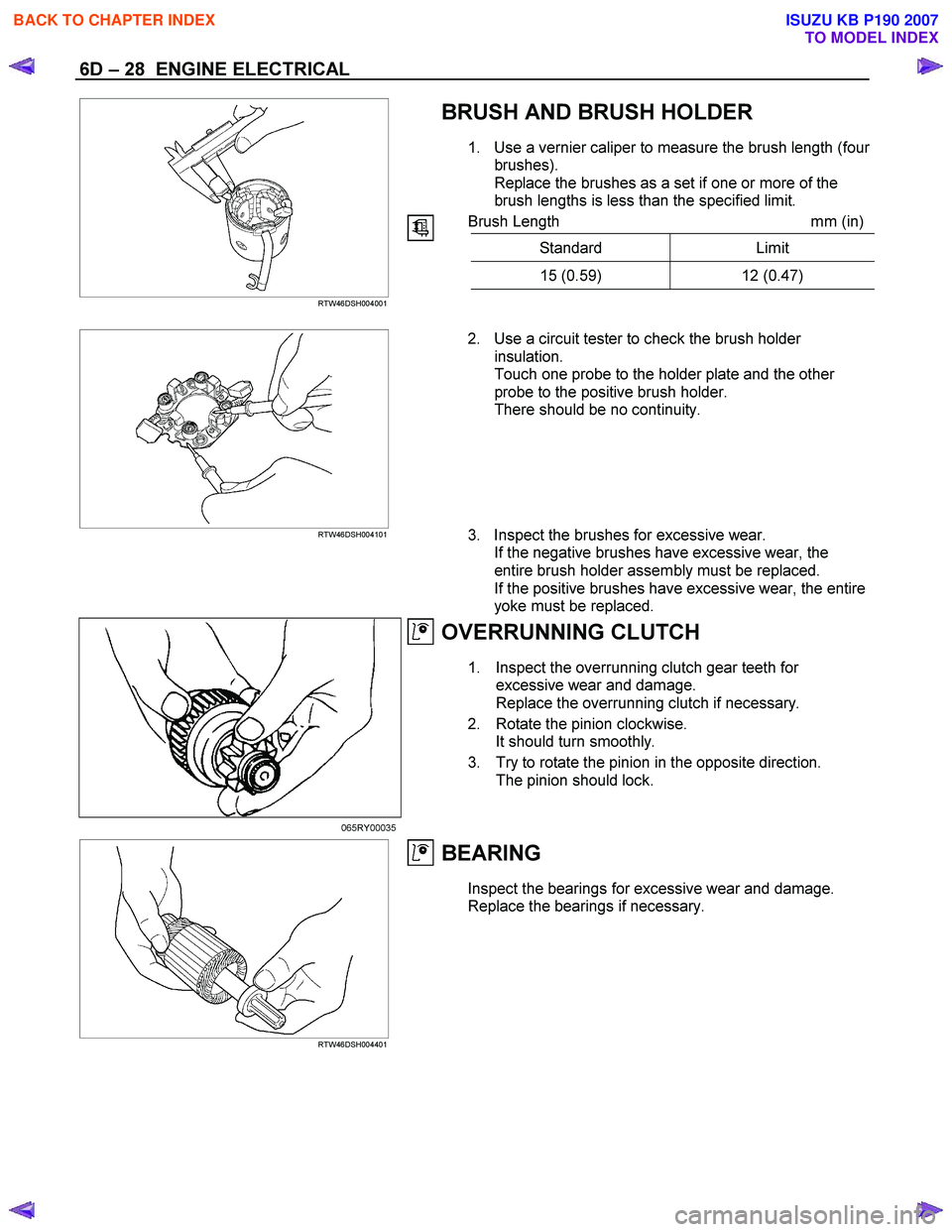
1. Use a vernier caliper to measure the brush length (four
brushes).
Replace the brushes as a set if one or more of the
brush lengths is less than the specified limit.
Brush Length mm (in)
Standard Limit
15 (0.59) 12 (0.47)
RTW46DSH004001
RTW46DSH004101
2. Use a circuit tester to check the brush holder
insulation.
Touch one probe to the holder plate and the other
probe to the positive brush holder.
There should be no continuity.
3. Inspect the brushes for excessive wear. If the negative brushes have excessive wear, the
entire brush holder assembly must be replaced.
If the positive brushes have excessive wear, the entire
yoke must be replaced.
OVERRUNNING CLUTCH
1. Inspect the overrunning clutch gear teeth for excessive wear and damage.
Replace the overrunning clutch if necessary.
2. Rotate the pinion clockwise. It should turn smoothly.
3. Try to rotate the pinion in the opposite direction. The pinion should lock.
065RY00035
RTW46DSH004401
BEARING
Inspect the bearings for excessive wear and damage.
Replace the bearings if necessary.
BACK TO CHAPTER INDEX
TO MODEL INDEX
ISUZU KB P190 2007
Page 1034 of 6020
ENGINE ELECTRICAL 6D – 33
PRE-HEATING SYSTEM
INSPECTION AND REPAIR
Make the necessary adjustments, repairs, and part replacement if excessive wear of damage is discovered during
inspection.
VISUAL CHECK
Check the main fuses and glow indicator for damage.
Replace the part(s) if required.
GLOW RELAY
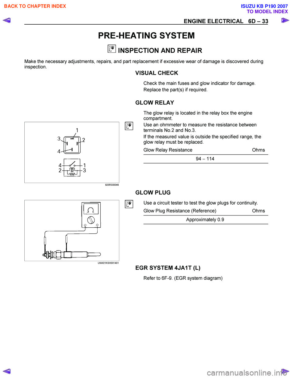
The glow relay is located in the relay box the engine
compartment.
825R300046
Use an ohmmeter to measure the resistance between
terminals No.2 and No.3.
If the measured value is outside the specified range, the
glow relay must be replaced.
Glow Relay Resistance Ohms
94 − 114
GLOW PLUG
LNW21KSH001401
Use a circuit tester to test the glow plugs for continuity.
Glow Plug Resistance (Reference) Ohms
Approximately 0.9
EGR SYSTEM 4JA1T (L)
Refer to 6F-9. (EGR system diagram)
BACK TO CHAPTER INDEX
TO MODEL INDEX
ISUZU KB P190 2007
Page 1037 of 6020
Engine Control System (4JH1) 6E-3
Rough, Unstable, or In co rr ect Idle And
Stallin g........................................................... .6E -260
Cut Out, Mi sses.............................................. .6E -262
Su rge s/Chuggle s............................................ .6E -263
La ck of Po wer, Sluggi shne ss, Spongine ss .... .6E -266
He sitation, Sag, Stu mble................................ .6E -268
Fuel Kno ck /Co mbu stion Noi se ....................... .6E -270
Poor F uel E cono my........................................ .6E -271
E xc ess ive S moke (B la ck S m oke) ................. .6E -272
E xc ess ive S moke (W hite S moke) ................. .6E -273
Repair In str u ctions ............................................ .6E -275
Engine Control Module (ECM) Replacement ..6E-275
Service Programming System (SPS)
Description .....................................................6E-276
Service Programming System (SPS)
(Remote Procedure) ......................................6E-277
Service Programming System (SPS)
(Pass-Thru Procedure) ..................................6E-278
Accelerator Pedal Position (APP) Sensor
Replacement ..................................................6E-279
Crankshaft Position Sensor (CKP) Sensor
Replacement ..................................................6E-279
EGR Solenoid Valve Replacement .................6E-280
Engine Coolant Temperature Coolant
(ECT) Sensor Replacement ...........................6E-280
Mass Air Flow (MAF) / Intake Air Temperature
Sensor Replacement......................................6E-280
Turbocharger Solenoid Valve Replacement
[High Altitude Spec] ........................................6E-281
Vacuum Pressure Sensor Replacement
[High Altitude Spec] ........................................6E-281
Vehicle Speed Sensor (VSS) Replacement ....6E-282
Description And Operation .................................6E-283 Engine Control Module (ECM) .......................6E-283
Engine Control Component Description ..........6E-284
Fuel Injection System Description ...................6E-288
Low Pressure Fuel Circuit Description ............6E-290
High Pressure Fuel Circuit Description ...........6E-291
Timing Control Device Description ..................6E-294
Exhaust Gas Recirculation (EGR) System
Description .....................................................6E-297
Turbocharger Description................................6E-298
Special Tools And Equipment ............................6E-299 Special Tools and Equipment .........................6E-299
BACK TO CHAPTER INDEX
TO MODEL INDEX
ISUZU KB P190 2007
Page 1065 of 6020
Engine Control System (4JH1) 6E-31
Diagnostic Starting Point - Engine Controls
Begin the system diagnosis with Diagnostic System
Check - Engine Controls. The Diagnostic System Check
- Engine Controls will provide the following information:
• The identification of the control modules which
command the system.
• The ability of the control modules to communicate
through the serial data circuit.
• The identification of any stored diagnostic trouble
codes (DTCs) and the their statuses.
The use of the Diagnostic System Check - Engine
Controls will identify the correct procedure fo
r
diagnosing the system and where the procedure is
located.
Important:
Engine Control System Check Sheet must be used to
verify the complaint vehicle, you need to know the
correct (normal) operating behavior of the system and
verify that the customer complaint is a valid failure o
f
the system.
Reading Flash Diagnostic Trouble Codes
The provision for communicating with the ECM is the
Data Link Connector (DLC). The DTCs stored in the
ECM memory can be read either through a hand-held
diagnostic scanner such as scan tool plugged into the
DLC or by counting the number of flashes of the MIL
when the diagnostic test terminal of the DLC is
grounded. The DLC terminal “6” (diagnostic request
switch) is pulled “Low” (grounded) by jumped to DLC
terminal “4”, which is a ground wire.
Once terminals “4” and “6” have been connected, the
ignition switch must be moved to the “ON” position, with
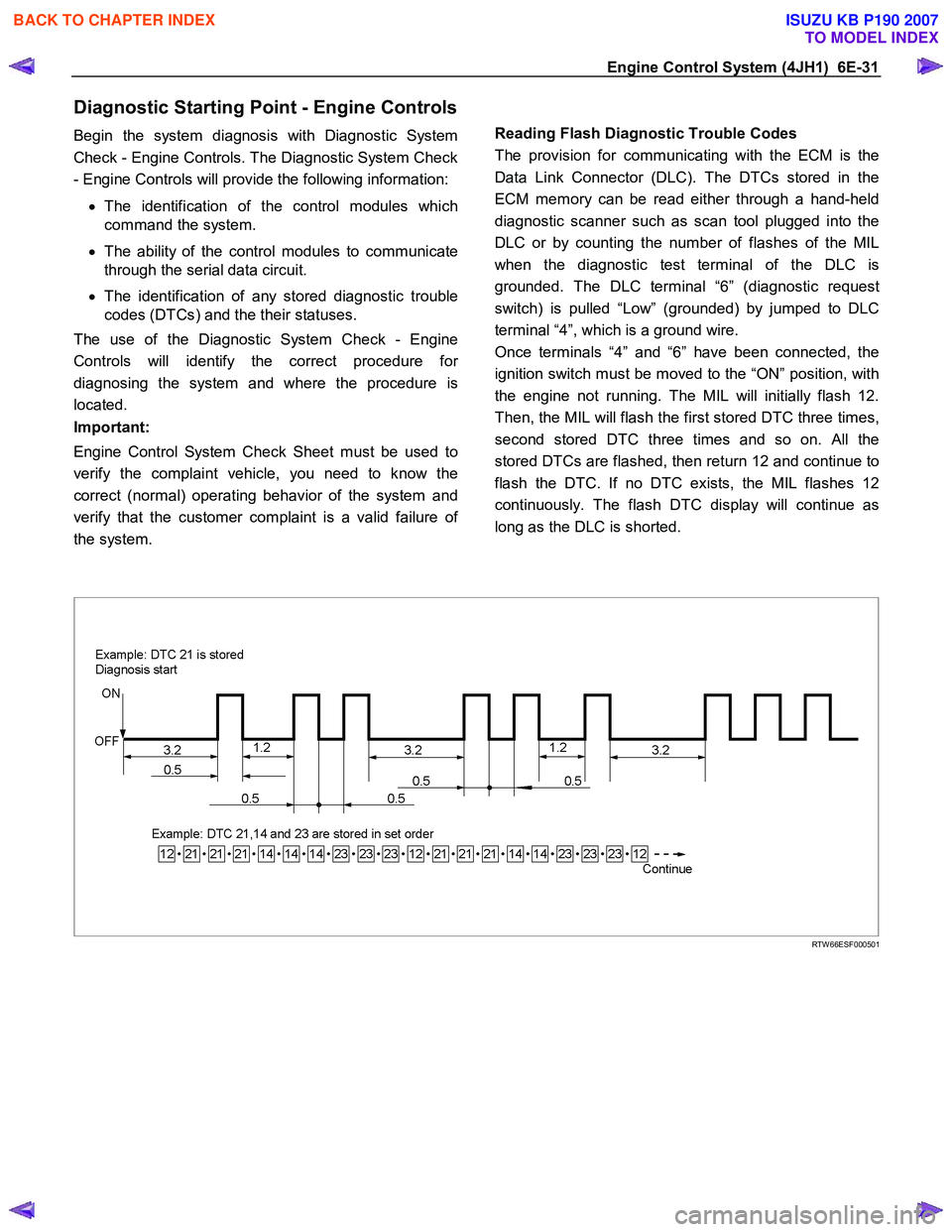
the engine not running. The MIL will initially flash 12.
Then, the MIL will flash the first stored DTC three times,
second stored DTC three times and so on. All the
stored DTCs are flashed, then return 12 and continue to
flash the DTC. If no DTC exists, the MIL flashes 12
continuously. The flash DTC display will continue as
long as the DLC is shorted.
RTW 66ESF000501
BACK TO CHAPTER INDEX
TO MODEL INDEX
ISUZU KB P190 2007
Page 1066 of 6020
6E-32 Engine Control System (4JH1)
Breaker Box
Breaker Box Connection Type A
RTW 66ESH003601
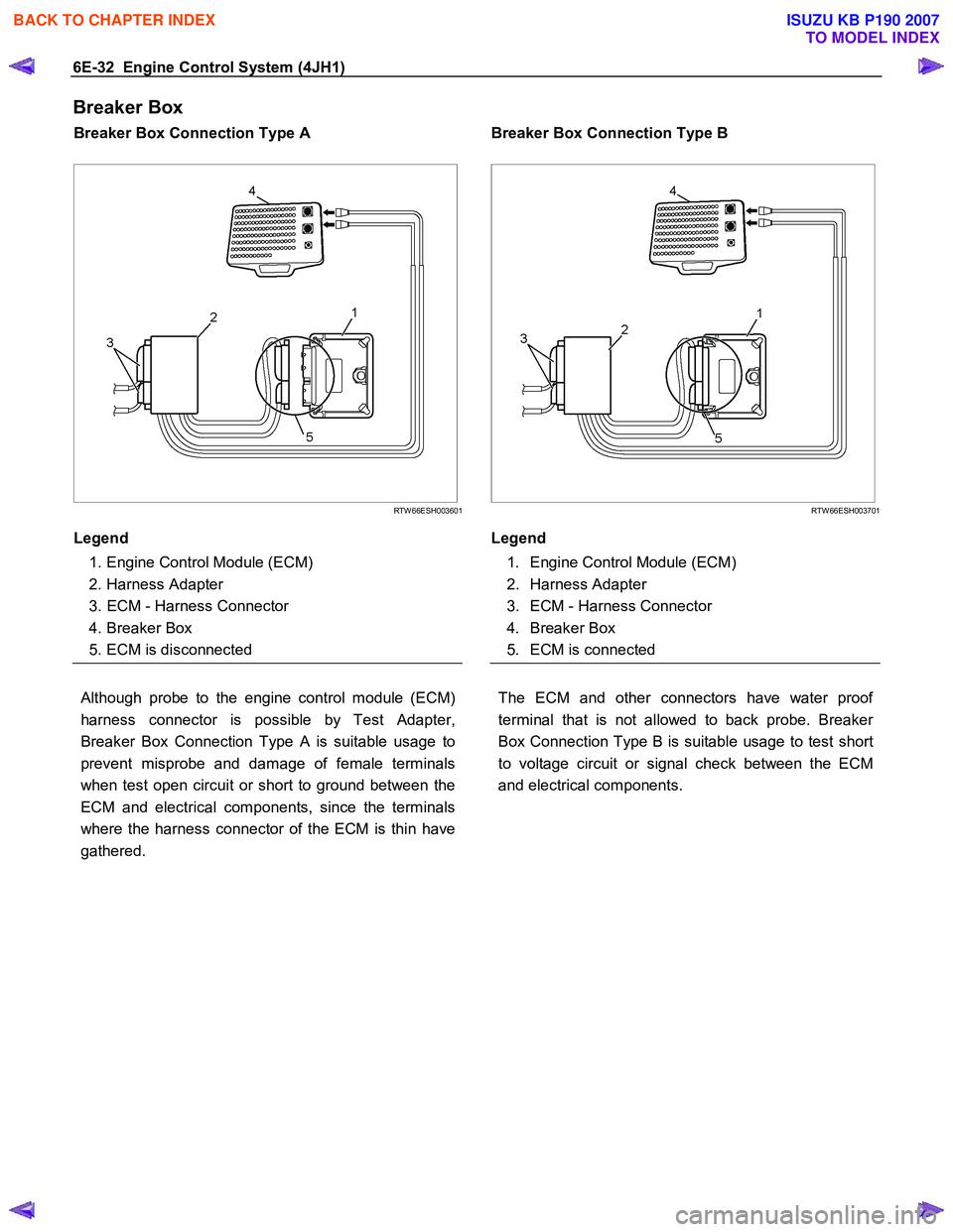
Legend
1. Engine Control Module (ECM)
2. Harness Adapter
3. ECM - Harness Connector
4. Breaker Box
5. ECM is disconnected
Breaker Box Connection Type B
RTW 66ESH003701
Legend
1. Engine Control Module (ECM)
2. Harness Adapter
3. ECM - Harness Connector
4. Breaker Box
5. ECM is connected
Although probe to the engine control module (ECM)
harness connector is possible by Test Adapter,
Breaker Box Connection Type A is suitable usage to
prevent misprobe and damage of female terminals
when test open circuit or short to ground between the
ECM and electrical components, since the terminals
where the harness connector of the ECM is thin have
gathered.
The ECM and other connectors have water proof
terminal that is not allowed to back probe. Breaker
Box Connection Type B is suitable usage to test short
to voltage circuit or signal check between the ECM
and electrical components.
BACK TO CHAPTER INDEX
TO MODEL INDEX
ISUZU KB P190 2007