2007 ISUZU KB P190 engine oil
[x] Cancel search: engine oilPage 2447 of 6020
ENGINE DRIVEABILITY AND EMISSIONS 6E–277
SPARK PLUG CABLES
The cable contains a synthetic conductor which is easily
damaged. Never stretch or kink the cable. Disconnect
the cable from spark plug and the ignition coil.
The original equipment cables and the ignition coil are
marked to show correct location of the cables. If spark
plug cables or the ignition coil are replaced previously,
before cables are removed from the ignition coil, mark
the cables and the coil so they can be reconnected in
the same position.
Inspection
NOTE: Never puncture the spark plug cable’s insulation
with a needle or the pointed end of a probe into the
cable. An increase in resistance would be created which
would cause the cable to become defective.
1. If the cable has broken or cracked insulation, it must be replaced.
2. If the terminals are corroded or loose, the cable must be replaced.
3. Check that the cable resistance does not exceed specified value.
#1 cylinder: 3.50k Ω - 5.24k Ω
#2 cylinder: 2.89k Ω - 4.33k Ω
#3 cylinder: 2.49k Ω - 3.73k Ω
#4 cylinder: 2.22k Ω - 3.32k Ω
EMISSION CONTROL ; *
**
*
CO ADJUSTER (W/
O CATALYSTIC CONVERTER)
* CO : Carbon monoxide
Location
Under the leht-hand side of the front sheet.
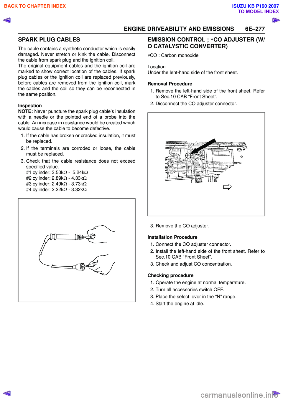
Removal Procedure 1. Remove the left-hand side of the front sheet. Refer to Sec.10 CAB “Front Sheet”.
2. Disconnect the CO adjuster connector.
3. Remove the CO adjuster.
Installation Procedure 1. Connect the CO adjuster connector.
2. Install the left-hand side of the front sheet. Refer to Sec.10 CAB “Front Sheet”.
3. Check and adjust CO concentration.
Checking procedure 1. Operate the engine at normal temperature.
2. Turn all accessories switch OFF.
3. Place the select lever in the “N” range.
4. Start the engine at idle.
BACK TO CHAPTER INDEX
TO MODEL INDEX
ISUZU KB P190 2007
Page 2465 of 6020
ENGINE LUBRICATION 6G-1
SECTION 6G
ENGINE LUBRICATION
TABLE OF CONTENTS
Service Precaution ......................................................................................................... 6G- 3
Oil Pump.......................................................................................................................... 6G- 4
Oil Pump and Associated Parts................................................................................ 6G- 4
Disassembly ............................................................................................................... 6G- 4
Inspection and Repair ............................................................................................... 6G- 5
Reassembly ................................................................................................................ 6G- 5
Oil Pan ............................................................................................................................. 6G- 6
Oil Pan and Associated Parts ................................................................................... 6G- 6
Disassembly ............................................................................................................... 6G- 6
Inspection and Repair ............................................................................................... 6G- 7
Reassembly ................................................................................................................ 6G- 7
General Descrip tion ....................................................................................................... 6G- 2
PA
GE
BACK TO CHAPTER INDEX
TO MODEL INDEX
ISUZU KB P190 2007
Page 2466 of 6020
6G-2 ENGINE LUBRICATION
General Description
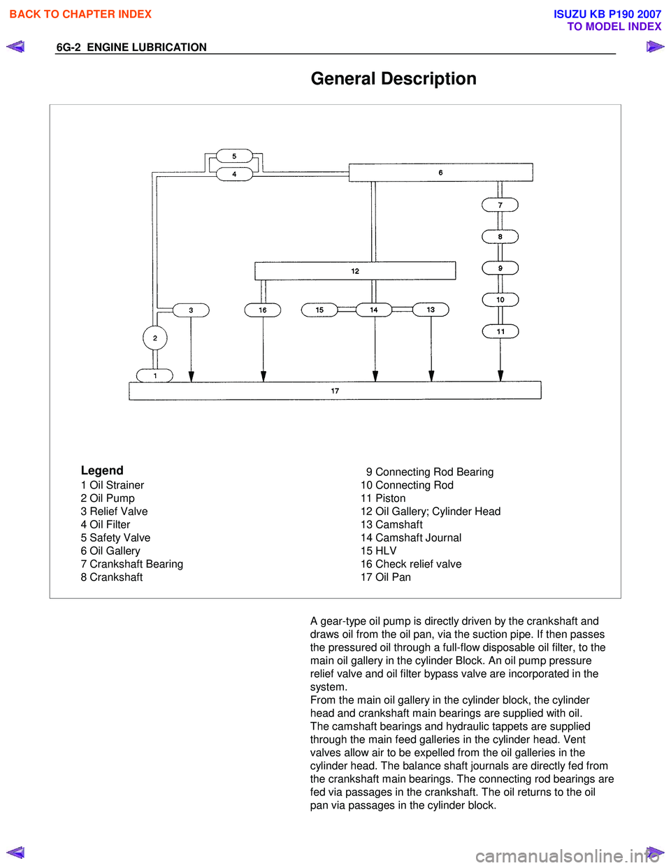
Legend
1 Oil Strainer
2 Oil Pump
3 Relief Valve
4 Oil Filter
5 Safety Valve
6 Oil Gallery
7 Crankshaft Bearing
8 Crankshaft 9 Connecting Rod Bearing
10 Connecting Rod
11 Piston
12 Oil Gallery; Cylinder Head
13 Camshaft
14 Camshaft Journal
15 HLV
16 Check relief valve
17 Oil Pan
A gear-type oil pump is directly driven by the crankshaft and
draws oil from the oil pan, via the suction pipe. If then passes
the pressured oil through a full-flow disposable oil filter, to the
main oil gallery in the cylinder Block. An oil pump pressure
relief valve and oil filter bypass valve are incorporated in the
system.
From the main oil gallery in the cylinder block, the cylinder
head and crankshaft main bearings are supplied with oil.
The camshaft bearings and hydraulic tappets are supplied
through the main feed galleries in the cylinder head. Vent
valves allow air to be expelled from the oil galleries in the
cylinder head. The balance shaft journals are directly fed from
the crankshaft main bearings. The connecting rod bearings are
fed via passages in the crankshaft. The oil returns to the oil
pan via passages in the cylinder block.
BACK TO CHAPTER INDEX
TO MODEL INDEX
ISUZU KB P190 2007
Page 2468 of 6020
6G-4 ENGINE LUBRICATION
Oil Pump
Oil Pump and Associated Parts
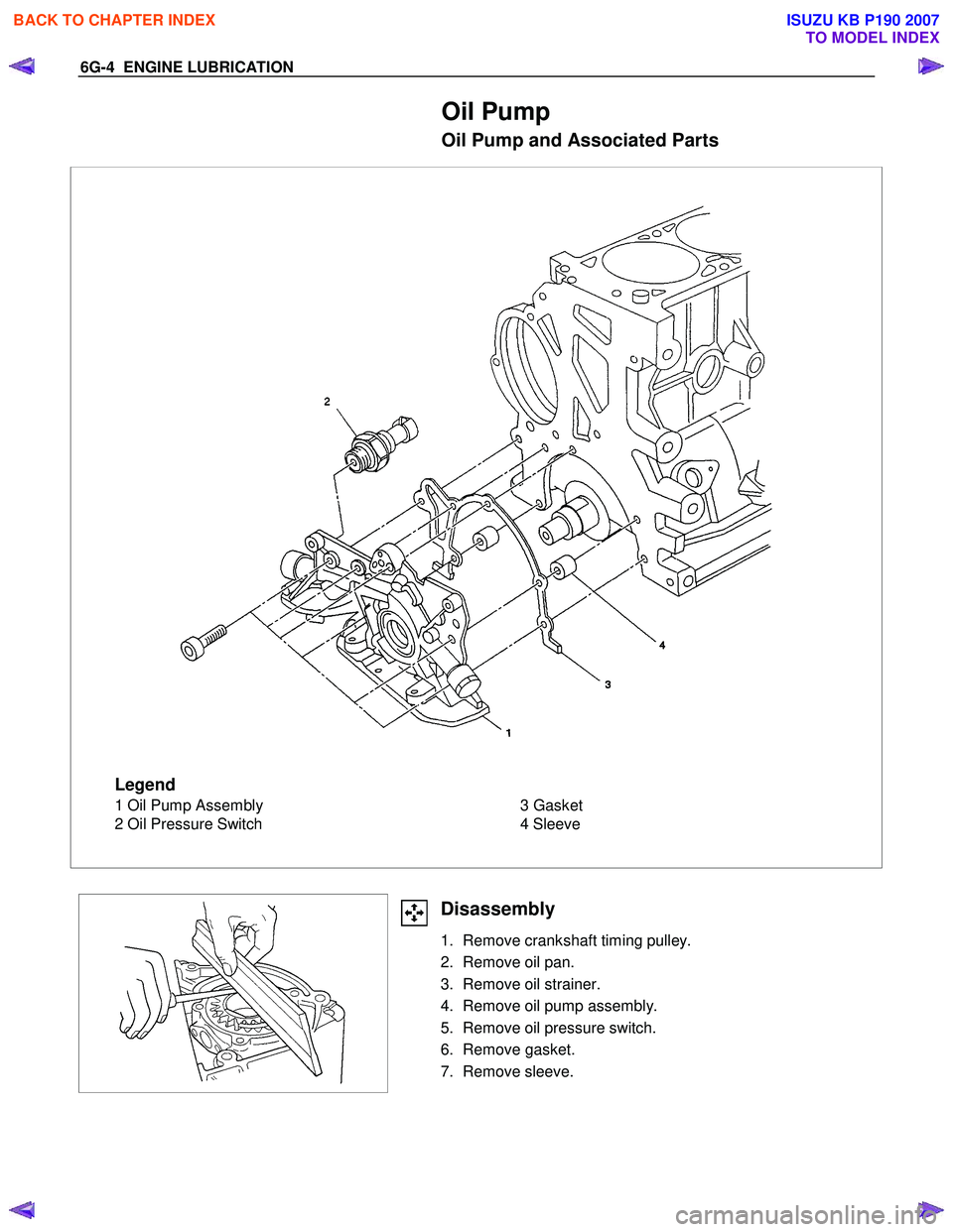
Legend
1 Oil Pump Assembly
2 Oil Pressure Switch 3 Gasket
4 Sleeve
Disassembly
1. Remove crankshaft timing pulley.
2. Remove oil pan.
3. Remove oil strainer.
4. Remove oil pump assembly.
5. Remove oil pressure switch.
6. Remove gasket.
7. Remove sleeve.
BACK TO CHAPTER INDEX
TO MODEL INDEX
ISUZU KB P190 2007
Page 2469 of 6020
ENGINE LUBRICATION 6G-5
Inspection and Repair
CAUTION: Make necessary correction or parts
replacement if wear, damage or any other abnormal
conditions are found through inspection.
Body and Gears
The pump assembly must be replaced if one or more of the
conditions below is discovered during inspection:
Indentation of gear pair - Use feeler strip and straight edge.
Dimension: 0.03 mm to 0.10 mm
(0.0012 to 0.0039 in)
Oil Strainer
Check the oil strainer for cracking and scoring. If cracking and
scoring are found, the oil strainer must be replaced.
Reassembly
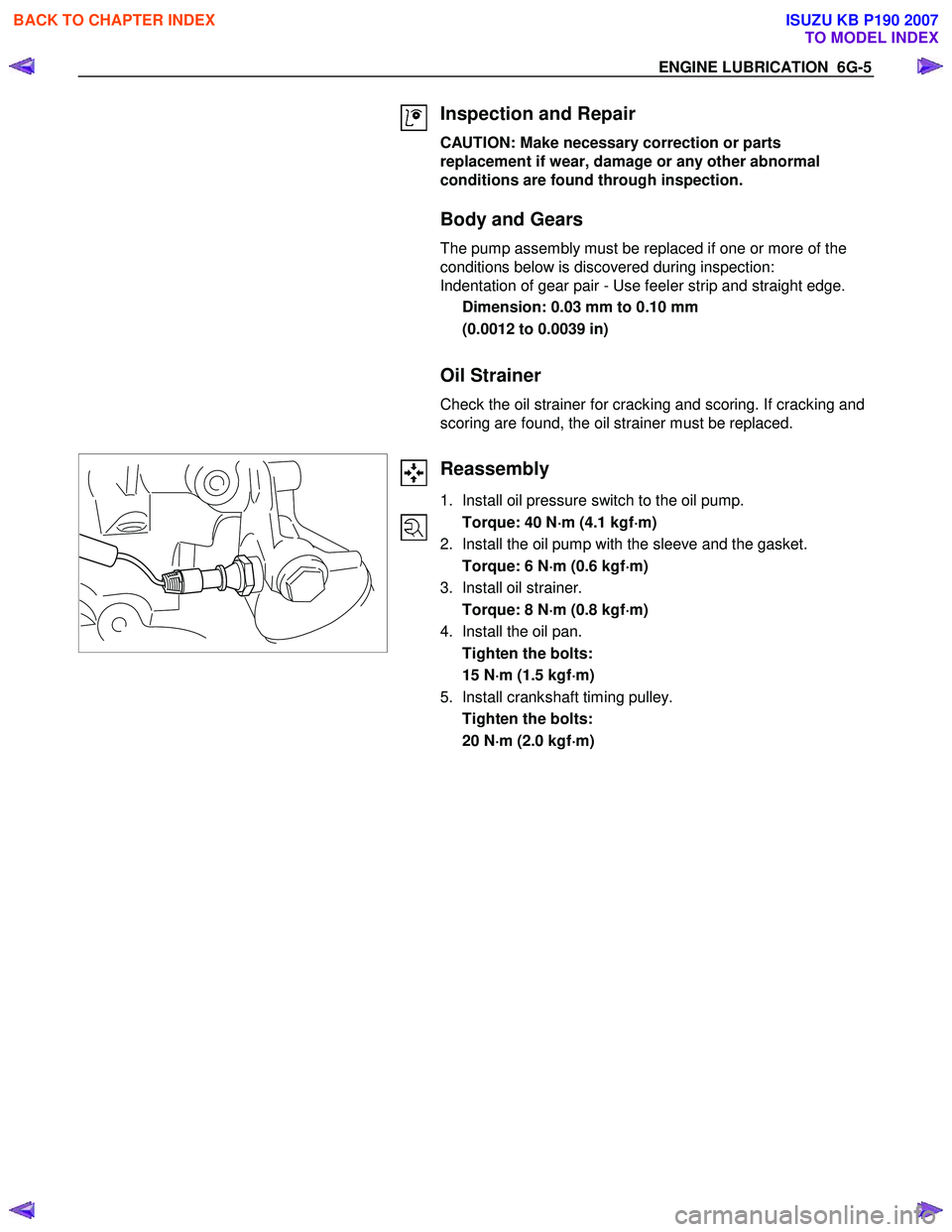
1. Install oil pressure switch to the oil pump.
Torque: 40 N ⋅
⋅⋅
⋅
m (4.1 kgf ⋅
⋅⋅
⋅
m)
2. Install the oil pump with the sleeve and the gasket.
Torque: 6 N ⋅
⋅⋅
⋅
m (0.6 kgf ⋅
⋅⋅
⋅
m)
3. Install oil strainer.
Torque: 8 N ⋅
⋅⋅
⋅
m (0.8 kgf ⋅
⋅⋅
⋅
m)
4. Install the oil pan.
Tighten the bolts:
15 N ⋅
⋅⋅
⋅
m (1.5 kgf ⋅
⋅⋅
⋅
m)
5. Install crankshaft timing pulley.
Tighten the bolts:
20 N ⋅
⋅⋅
⋅
m (2.0 kgf ⋅
⋅⋅
⋅
m)
BACK TO CHAPTER INDEX
TO MODEL INDEX
ISUZU KB P190 2007
Page 2470 of 6020
6G-6 ENGINE LUBRICATION
Oil Pan
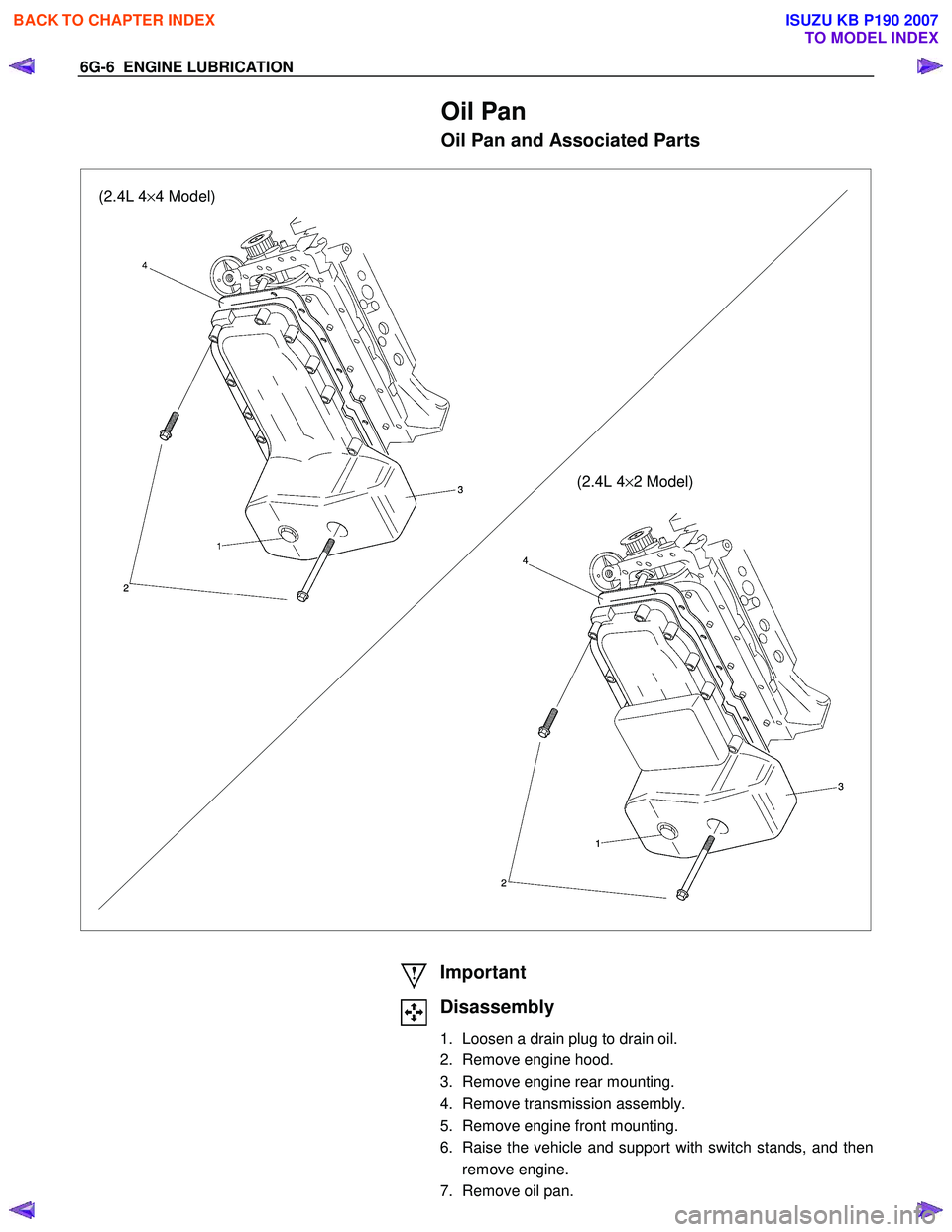
Oil Pan and Associated Parts
(2.4L 4×4 Model)
(2.4L 4×2 Model)
Important
Disassembly
1. Loosen a drain plug to drain oil.
2. Remove engine hood.
3. Remove engine rear mounting.
4. Remove transmission assembly.
5. Remove engine front mounting.
6. Raise the vehicle and support with switch stands, and then remove engine.
7. Remove oil pan.
BACK TO CHAPTER INDEX
TO MODEL INDEX
ISUZU KB P190 2007
Page 2471 of 6020
ENGINE LUBRICATION 6G-7
Inspection and Repair
CAUTION: Make necessary correction or parts replacement if wear, damage or any other
abnormal conditions are found through
inspection.
Reassembly
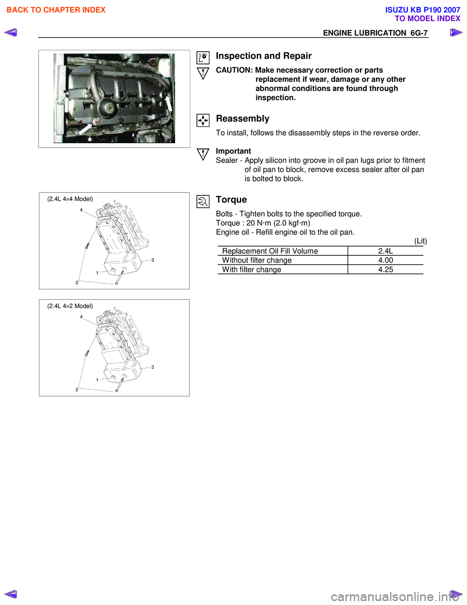
To install, follows the disassembly steps in the reverse order.
Important
Sealer - Apply silicon into groove in oil pan lugs prior to fitment of oil pan to block, remove excess sealer after oil pan
is bolted to block.
(2.4L 4 ×4 Model)
4
3
1
2
(2.4L 4 ×2 Model)
4
3
1
2
Torque
Bolts - Tighten bolts to the specified torque.
Torque : 20 N �xm (2.0 kgf �xm)
Engine oil - Refill engine oil to the oil pan. (Lit)
Replacement Oil Fill Volume 2.4L
W ithout filter change 4.00
W ith filter change 4.25
BACK TO CHAPTER INDEX
TO MODEL INDEX
ISUZU KB P190 2007
Page 2480 of 6020
Engine Mechanical – V6 Page 6A1–1
6A1
Engine Mechanical – V6
ATTENTION
Before performing any service operation or other procedure described in this Section, refer to 1.1
WARNING, CAUTION and NOTES for correct workshop practices with regard to safety and/or property
damage.
1 General Information ............................................................................................................ ...................8
1.1 WARNING, CAUTION and NOTES .................................................................................................... ................... 8
Definition of WARNING, CAUTION and NOTE Statements ............................................................................. .... 8
WARNING defined ............................................................................................................................................. 8
CAUTION defined .............................................................................................................................................. 8
NOTE defined..................................................................................................................................................... 9
1.2 Engine Components .............................................................................................................................................. 9
Major Component Assemblies..................................................................................................... ......................... 9
Intake Manifold Assembly ................................................................................................................................... 10
Engine Front Cover.............................................................................................................................................. 12
Camshaft Timing Components ..................................................................................................... ...................... 13
Camshaft Cover Assembly.................................................................................................................................. 14
Cylinder Head Assembly ..................................................................................................................................... 15
Oil Pump ............................................................................................................................................................... 16
Engine Block Assembly .......................................................................................................... ............................ 17
Pistons, Rings, Bearing and Connecting Rod ..................................................................................... .............. 18
Oil Pan Assembly................................................................................................................................................. 19
Oil Filter Assembly .............................................................................................................................................. 20
1.3 Engine Serial Number........................................................................................................... ............................... 20
1.4 Engine Construction............................................................................................................................................ 21
Cylinder Block ...................................................................................................................................................... 21
Cylinder Heads ................................................................................................................. .................................... 21
Crankshaft ............................................................................................................................................................ 22
Pistons, Pins and Connecting Rods .............................................................................................. .................... 22
Camshaft Drive System ....................................................................................................................................... 22
1.5 Engine Lubrication System ...................................................................................................... ........................... 24
Lubrication Description....................................................................................................................................... 24
1.6 Service Notes ....................................................................................................................................................... 24
Cleanliness and Care........................................................................................................... ................................ 24
Replacing Engine Gaskets ....................................................................................................... ........................... 24
Re-Using Gaskets and Applying Sealants......................................................................................... ............... 24
Separating Components................................................................................................................................... 24
Cleaning Gasket Surfaces................................................................................................................................ 24
Assembling Components .......................................................................................................... ....................... 25
Use of Room Temperature Vulcanising and Anaerobic Sealer....................................................................... .25
Room Temperature Vulcanising Sealer............................................................................................................ 25
Anaerobic Sealer .............................................................................................................................................. 25
Pipe Joint Compound ............................................................................................................ ........................... 26
Separating Parts .................................................................................................................................................. 26
Tools and Equipment ............................................................................................................ .............................. 26
Fasteners .............................................................................................................................................................. 27
Clamp Load ..................................................................................................................... ................................. 27
Torque Angle and Torque to Yield Fasteners..................................................................................... .............. 27
2 Diagnosis ..............................................................................................................................................28
2.1 Engine Diagnosis ............................................................................................................... .................................. 28
2.2 Symptoms............................................................................................................................................................. 28
Strategy Based Diagnosis ....................................................................................................... ............................ 28
BACK TO CHAPTER INDEX
TO MODEL INDEX
ISUZU KB P190 2007