2007 ISUZU KB P190 engine oil
[x] Cancel search: engine oilPage 2180 of 6020
6E–10 ENGINE DRIVEABILITY AND EMISSIONS
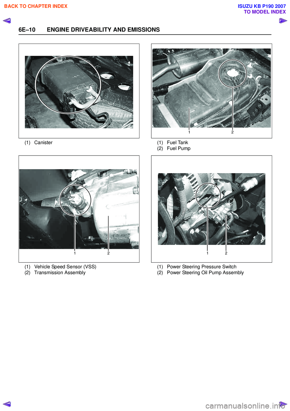
(1) Canister(1)
(2) Fuel Tank
Fuel Pump
2
1
(1)
(2) Vehicle Speed Sensor (VSS)
Transmission Assembly
12
(1)
(2) Power Steering Pressure Switch
Power Steering Oil Pump Assembly
12
BACK TO CHAPTER INDEX
TO MODEL INDEX
ISUZU KB P190 2007
Page 2198 of 6020
6E–28 ENGINE DRIVEABILITY AND EMISSIONS
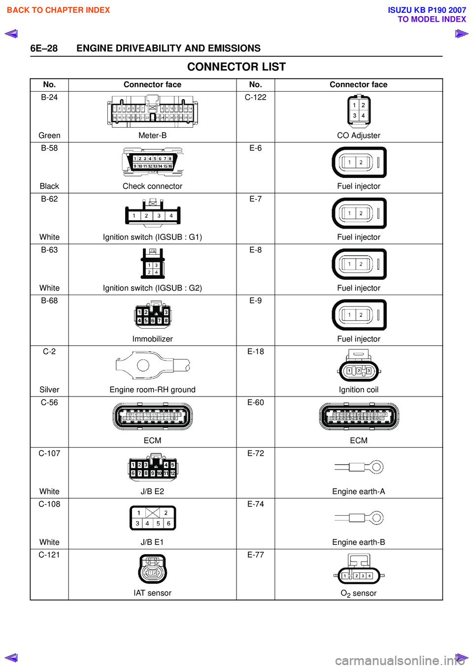
CONNECTOR LIST
No.Connector face No.Connector face
B-24
Green Meter-B C-122
CO Adjuster
B-58
Black Check connector E-6
Fuel injector
B-62
White Ignition switch (IGSUB : G1) E-7
Fuel injector
B-63
White Ignition switch (IGSUB : G2) E-8
Fuel injector
B-68
Immobilizer E-9
Fuel injector
C-2
Silver Engine room-RH ground E-18
Ignition coil
C-56
ECM E-60
ECM
C-107
White J/B E2 E-72
Engine earth-A
C-108
White J/B E1 E-74
Engine earth-B
C-121
IAT sensor E-77
O
2 sensor
BACK TO CHAPTER INDEX
TO MODEL INDEX
ISUZU KB P190 2007
Page 2202 of 6020
6E–32 ENGINE DRIVEABILITY AND EMISSIONS
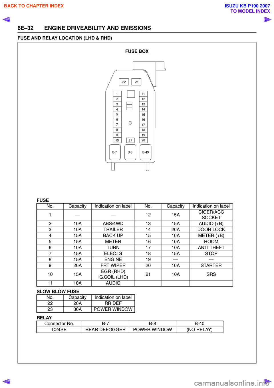
FUSE AND RELAY LOCATION (LHD & RHD)
FUSE
SLOW BLOW FUSE
RELAY No. Capacity Indication on label No. Capacity Indication on label
1— — 1 215A CIGER/ACC
SOCKET
2 10A ABS/4WD 13 15A AUDIO (+B)
3 10A TRAILER 14 20A DOOR LOCK
4 15A BACK UP 15 10A METER (+B)
5 15A METER16 10A ROOM
6 10A TURN17 10A ANTI THEFT
7 15A ELEC.IG 18 15ASTOP
815A ENGINE 19 — —
9 20A FRT WIPER 20 10A STARTER
10 15A EGR (RHD)
IG.COIL (LHD) 21 10A
SRS
11 10A AUDIO
No. Capacity Indication on label 22 20A RR DEF
23 30A POWER WINDOW
Connector No. B-7B-8B-40
C24SE REAR DEFOGGER POWER WINDOW (NO RELAY)
FUSE BOX
BACK TO CHAPTER INDEX
TO MODEL INDEX
ISUZU KB P190 2007
Page 2212 of 6020

6E–42 ENGINE DRIVEABILITY AND EMISSIONS
ECM CONNECTOR PIN ASSIGNMENT & OUTPUT SIGNAL
Connector J1 Port: View Looking Into ECM Case
1
17 16
32
PIN16
PIN1
PIN17 PIN32
Pin
No. B/
Box
No. Pin Function
Wire
Color Signal or Continuity
ECM
Connection Tester Position
Key SW Off Key SW
On Engine
Idle Engine
2000rpm Range (+) (-)
J1-1 J1-1 Ground BLK/
WHT Continuity
with
ground -
- - Disconnect ΩJ1-1 GND
J1-2 J1-2 Ground BLK/
WHT Continuity
with
ground -
- - Disconnect ΩJ1-2 GND
J1-3 J1-3 Knock Sensor Signal YEL Less than 1V--- ----
J1-4 J1-4 No Connection - --- - -- - -
J1-5 J1-5 Canister Purge Solenoid Valve RED/
YEL Less than
1V Wave form G or 12-14V
Connect DC V J1-5 GND
J1-6 J1-6 Crankshaft Position (CKP) Sensor (Ground) RED Approx.
0.58kΩ -
- - Disconnect ΩJ1-6 J1-21
J1-7 J1-7 Throttle Position Sensor (TPS) Output
Signal BLU Less than
1V Approx 0.7V Approx
0.8VConnect DC V J1-7 J1-32
J1-8 J1-8 No. 3 Injector GRN/
BLK Less than
1V Wave form E or 12-14V
Connect DC V J1-8 GND
J1-9 J1-9 No. 1 Injector GRN/
WHT Less than
1V Wave form E or 12-14V
Connect DC V J1-9 GND
J1-10 J1-10 No Connection - --- - -- - -
J1-11 J1-11 No. 4 Injector GRN Less than
1V Wave form E or 12-14V
Connect DC V J1-11 GND
J1-12 J1-12 No Connection - --- - -- - -
J1-13 J1-13 Idle Air Control Valve (IACV) Coil B High BLU/
RED Less than
1V Less than 1V / 10-14V
Connect DC V J1-13 GND
J1-14 J1-14 No Connection - --- - -- - -
J1-15 J1-15 Throttle Position Sensor (TPS) Power
Supply RED Less than
1V Approx. 5V
Connect DC V J1-15 J1-32
J1-16 J1-16 MAP Sensor Ground GRN Continuity with
ground -
- - Connect ΩJ1-16 GND
J1-17 J1-17 Ground BLK/
WHT Continuity
with
ground -
- - Connect ΩJ1-17 GND
J1-18 J1-18 Coil Module 2 (No. 2 & 3 Cylinder) BLU -
-Wave form F -- - -
J1-19 J1-19 Coil Module 1 (No. 1 & 4 Cylinder) GRN -
-Wave form F -- - -
J1-20 J1-20 No Connection - --- - -- - -
BACK TO CHAPTER INDEX
TO MODEL INDEX
ISUZU KB P190 2007
Page 2213 of 6020

ENGINE DRIVEABILITY AND EMISSIONS 6E–43
J1-21 J1-21 Crankshaft Position (CKP) Sensor Signal WHT - - Wave form
or approx. 3.7V Wave form
A or
approx. 7.8V Connect AC V J1-21 J1-6
J1-22 J1-22 No.2 Injector GRN/
WHT Less than
1V Wave form E or 12-14V
Connect DC V J1-22 GND
J1-23 J1-23 No Connection - --- - -- - -
J1-24 J1-24 MAP Sensor Signal GRY Less than 1VApprox.
4.8V Approx.
1.3V Approx.
0.9V Connect DC V J1-24 J1-16
J1-25 J1-25 No Connection - --- - -- - -
J1-26 J1-26 No Connection - --- - -- J1-26 -
J1-27 J1-27 Engine Coolant Temp. (ECT) Sensor Signal GRY Less than
1V
20℃: Approx. 2.4V / 40 ℃: Approx. 1.4V or
4.1V / 60 ℃: Approx. 3.3V / 80 ℃: Approx.
2.5VConnect DC V J1-27 J1-32
J1-28 J1-28 Idle Air Control Valve (IACV) Coil A High BLU Less than
1V Less than 1V / 10-14V
Connect DC V J1-28 GND
J1-29 J1-29 Idle Air Control Valve (IACV) Coil B Low BLU/
BLK Less than
1V Less than 1V / 10-14V
Connect DC V J1-29 GND
J1-30 J1-30 Idle Air Control Valve (IACV) Coil A Low BLU/
WHT Less than
1V Less than 1V / 10-14V
Connect DC V J1-30 GND
J1-31 J1-31 MAP Sensor Power Supply RED Less than
1V Approx.. 5V
Connect DC V J1-31 J1-16
J1-32 J1-32 ECT Sensor, Knock Sensor, Throttle
Position Sensor Ground GRN Continuity
with
ground -
- - Connect ΩJ1-32 GND
Pin
No. B/
Box No. Pin Function
Wire
Color Signal or Continuity
ECM
Connection Tester Position
Key SW Off Key SW
On Engine
Idle Engine
2000rpm Range (+) (-)
BACK TO CHAPTER INDEX
TO MODEL INDEX
ISUZU KB P190 2007
Page 2216 of 6020
6E–46 ENGINE DRIVEABILITY AND EMISSIONS
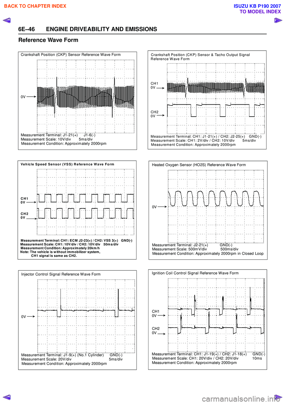
Reference Wave Form
Crankshaft Position (CKP) Sensor Reference W ave Form
0V
Measurem ent Term inal: J1-21(+) J1-6(-)
Measurem ent Scale: 10V/div 5m s/div
Measurem ent Condition: Approxim ately 2000rpm
Vehicle Speed Sensor (VSS) Reference Wave Form
CH1
0V
CH2
0V
M easurem ent Term inal: CH1: ECM J2-23(+) / CH2: VSS 3(+) GND(-)
M easurem ent Scale: CH1: 10V/div / CH2: 10V/div 50m s/div
Measurem ent Condition: Approxim ately 20km /h
Note: The vehicle is w ithout imm obilizer system,
CH1 signal is same as CH2.
Injector Control Signal Reference W ave Form
0V
Measurem ent Term inal: J1-9(+) (No.1 Cylinder) GND(-)
Measurement Scale: 20V/div 5ms/div
Measurem ent Condition: Approximately 2000rpm
Crankshaft Position (CKP) Sensor & Tacho Output Signal
Reference W ave Form
CH1
0V
CH2
0V
Measurement Terminal: CH1: J1-21(+) / CH2: J2-25(+) GND(-)
Measurement Scale: CH1: 2V/div / CH2: 10V/div 5ms/div
Measurement Condition: Approximately 2000rpm
Heated Oxygen Sensor (HO2S) Reference Wave Form
0V
Measurem ent Terminal: J2-21(+) GND(-)
Measurem ent Scale: 500m V/div 500m s/div
Measurement Condition: Approxim ately 2000rpm in Closed Loop
Ignition Coil Control Signal Reference Wave Form
CH1
0V
CH2
0V
Measurement Terminal: CH1: J1-19(+) / CH2: J1-18(+) GND(-)
Measurem ent Scale: CH1: 20V/div / CH2: 20V/div 10m s
Measurement Condition: Approximately 2000rpm
BACK TO CHAPTER INDEX
TO MODEL INDEX
ISUZU KB P190 2007
Page 2219 of 6020

ENGINE DRIVEABILITY AND EMISSIONS 6E–49
Throttle Position Sensor (TPS)
The TPS is a potentiometer connected to throttle shaft
on the throttle body.
The engine control module (ECM) monitors the voltage
on the signal line and calculates throttle position. As the
throttle valve angle is changed when accelerator pedal
moved. The TPS signal also changed at a moved
throttle valve. As the throttle valve opens, the output
increases so that the output voltage should be high.
The throttle body has a throttle plate to control the
amount of the air delivered to the engine.
Engine coolant is directed through a coolant cavity in
the throttle body to warm the throttle valve and to
prevent icing.
Idle Air Control (IAC) Valve
The idle air control valve (IAC) valve is two directional
and gives 2-way control. With power supply to the coils
controlled steps by the engine control module (ECM),
the IAC valve's pintle is moved to adjust idle speed,
raising it for fast idle when cold or there is extra load
from the air conditioning or power steering.
By moving the pintle in (to decrease air flow) or out (to
increase air flow), a controlled amount of the air can
move around the throttle plate. If the engine speed is
too low, the engine control module (ECM) will retract the
IAC pintle, resulting in more air moving past the throttle
plate to increase the engine speed.
If the engine speed is too high, the engine control
module (ECM) will extend the IAC pintle, allowing less
air to move past the throttle plate, decreasing the
engine speed.
The IAC pintle valve moves in small step called counts.
During idle, the proper position of the IAC pintle is
calculated by the engine control module (ECM) based
on battery voltage, coolant temperature, engine load,
and engine speed.
If the engine speed drops below a specified value, and
the throttle plate is closed, the engine control module
(ECM) senses a near-stall condition. The engine control
module (ECM) will then calculate a new IAC pintle valve
position to prevent stalls.
If the IAC valve is disconnected and reconnected with
the engine running, the idle speed will be wrong. In this
case, the IAC must be reset. The IAC resets when the
key is cycled “On” then “Off”. When servicing the IAC, it
should only be disconnected or connected with the
ignition “Off”.
The position of the IAC pintle valve affects engine start-
up and the idle characteristic of the vehicle.
If the IAC pintle is fully open, too much air will be
allowed into the manifold. This results in high idle
speed, along with possible hard starting and lean air/
fuel ratio.
(1) Throttle Position Sensor
(2) Idle Air Control (IAC) Valve
1
2
C harac teris t ic of TPS -R ef erenc e-
0
0.5
1
1.5 2
2.5
3
3.5 4
4.5 5
0 10 2030 405060 7080 90100 Throt t le Angle (% ) (Tec h2 R eading)
Output Voltage (V)
StepCoilAB CDCoil A H igh
(ECM J1-28) On On
Coil A Low
(ECM J1-30) On On
Coil B H igh
(ECM J1-13) On On
Coil B Low
(ECM J1-29) On On
(IAC Valve Close Direction)
(IAC Valve Open Direction)
BACK TO CHAPTER INDEX
TO MODEL INDEX
ISUZU KB P190 2007
Page 2224 of 6020
6E–54 ENGINE DRIVEABILITY AND EMISSIONS
GENERAL DESCRIPTION FOR ELECTRIC
IGNITION SYSTEM
The engine use two ignition coils, one per two cylinders.
A two wire connector provides a battery voltage primary
supply through the ignition fuse.
The ignition control spark timing is the ECM’s method of
controlling the spark advance and the ignition dwell.
The ignition control spark advance and the ignition dwell
are calculated by the ECM using the following inputs.
• Engine speed
• Crankshaft position (CKP) sensor
• Engine coolant temperature (ECT) sensor
• Throttle position sensor
• Vehicle speed sensor
• ECM and ignition system supply voltage
Ignition coil works to generate only the secondary
voltage be receiving the primary voltage from ECM.
The primary voltage is generated at the coil driver
located in the ECM. The coil driver generate the primary
voltage based on the crankshaft position signal. In
accordance with the crankshaft position signal, ignition
coil driver determines the adequate ignition timing and
also cylinder number to ignite.
Ignition timing is determined the coolant temperature,
intake air temperature, engine speed, engine load,
knock sensor signal, etc.
Spark Plug
Although worn or dirty spark plugs may give satisfactory
operation at idling speed, they frequently fail at higher
engine speeds. Faulty spark plugs may cause poor fuel
economy, power loss, loss of speed, hard starting and
generally poor engine performance. Follow the
scheduled maintenance service recommendations to
ensure satisfactory spark plug performance. Refer to
Maintenance and Lubrication .
Normal spark plug operation will result in brown to
grayish-tan deposits appearing on the insulator portion
of the spark plug. A small amount of red-brown, yellow,
and white powdery material may also be present on the
insulator tip around the center electrode. These
deposits are normal combustion by-products of fuels
and lubricating oils with additives. Some electrode wear
will also occur. Engines which are not running properly
are often referred to as “misfiring.” This means the
ignition spark is not igniting the air/fuel mixture at the
proper time. While other ignition and fuel system causes
must also be considered, possible causes include
ignition system conditions which allow the spark voltage
to reach ground in some other manner than by jumping
across the air gap at the tip of the spark plug, leaving
the air/fuel mixture unburned. Misfiring may also occur
when the tip of the spark plug becomes overheated and
ignites the mixture before the spark jumps. This is
referred to as “pre-ignition.”
Spark plugs may also misfire due to fouling, excessive
gap, or a cracked or broken insulator. If misfiring occurs before the recommended replacement interval, locate
and correct the cause.
Carbon fouling of the spark plug is indicated by dry,
black carbon (soot) deposits on the portion of the spark
plug in the cylinder. Excessive idling and slow speeds
under light engine loads can keep the spark plug
temperatures so low that these deposits are not burned
off. Very rich fuel mixtures or poor ignition system output
may also be the cause. Refer to DTC P1167.
Oil fouling of the spark plug is indicated by wet oily
deposits on the portion of the spark plug in the cylinder,
usually with little electrode wear. This may be caused by
oil during break-in of new or newly overhauled engines.
Deposit fouling of the spark plug occurs when the
normal red-brown, yellow or white deposits of
combustion by-products become sufficient to cause
misfiring. In some cases, these deposits may melt and
form a shiny glaze on the insulator around the center
electrode. If the fouling is found in only one or two
cylinders, valve stem clearances or intake valve seals
may be allowing excess lubricating oil to enter the
cylinder, particularly if the deposits are heavier on the
side of the spark plug facing the intake valve.
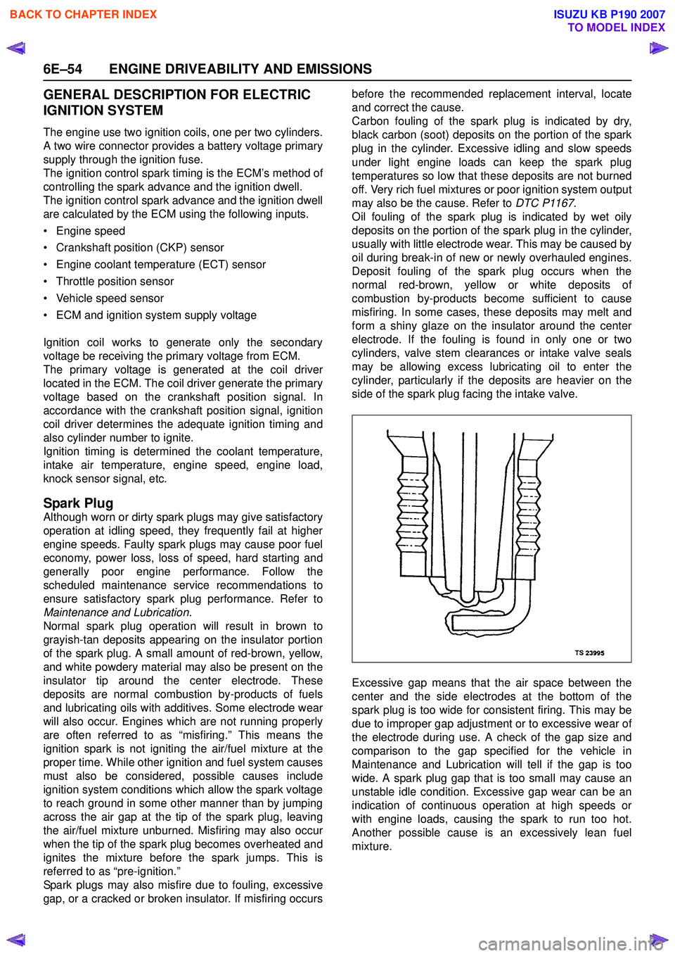
Excessive gap means that the air space between the
center and the side electrodes at the bottom of the
spark plug is too wide for consistent firing. This may be
due to improper gap adjustment or to excessive wear of
the electrode during use. A check of the gap size and
comparison to the gap specified for the vehicle in
Maintenance and Lubrication will tell if the gap is too
wide. A spark plug gap that is too small may cause an
unstable idle condition. Excessive gap wear can be an
indication of continuous operation at high speeds or
with engine loads, causing the spark to run too hot.
Another possible cause is an excessively lean fuel
mixture.
BACK TO CHAPTER INDEX
TO MODEL INDEX
ISUZU KB P190 2007