2007 ISUZU KB P190 Circuit
[x] Cancel search: CircuitPage 1730 of 6020
ENGINE CONTROL SYSTEM (4JK1/4JJ1) 6E-113
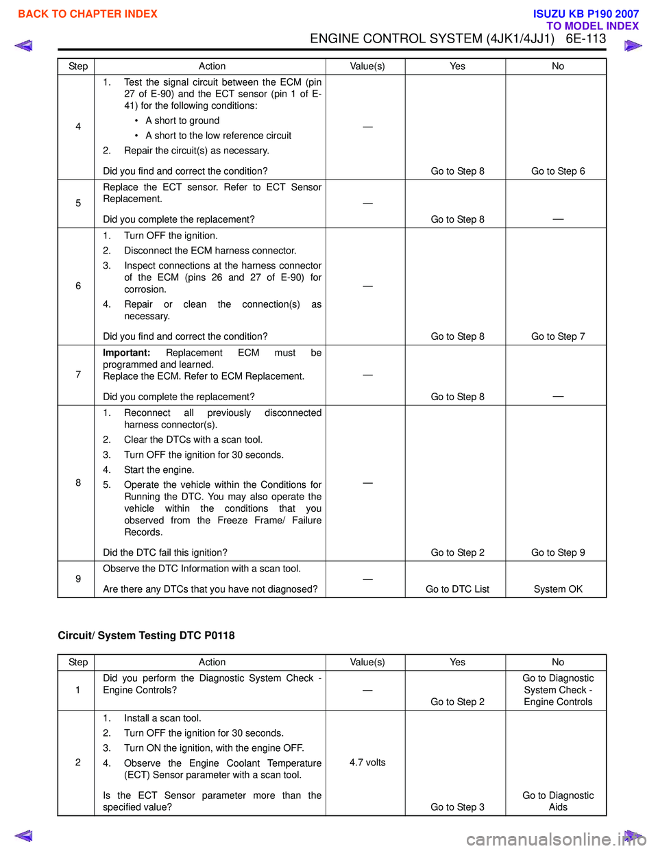
Circuit/ System Testing DTC P0118
41. Test the signal circuit between the ECM (pin
27 of E-90) and the ECT sensor (pin 1 of E-
41) for the following conditions:
• A short to ground
• A short to the low reference circuit
2. Repair the circuit(s) as necessary.
Did you find and correct the condition? —
Go to Step 8 Go to Step 6
5 Replace the ECT sensor. Refer to ECT Sensor
Replacement.
Did you complete the replacement? —
Go to Step 8
—
61. Turn OFF the ignition.
2. Disconnect the ECM harness connector.
3. Inspect connections at the harness connector of the ECM (pins 26 and 27 of E-90) for
corrosion.
4. Repair or clean the connection(s) as necessary.
Did you find and correct the condition? —
Go to Step 8 Go to Step 7
7 Important:
Replacement ECM must be
programmed and learned.
Replace the ECM. Refer to ECM Replacement.
Did you complete the replacement? —
Go to Step 8
—
81. Reconnect all previously disconnected
harness connector(s).
2. Clear the DTCs with a scan tool.
3. Turn OFF the ignition for 30 seconds.
4. Start the engine.
5. Operate the vehicle within the Conditions for Running the DTC. You may also operate the
vehicle within the conditions that you
observed from the Freeze Frame/ Failure
Records.
Did the DTC fail this ignition? —
Go to Step 2 Go to Step 9
9 Observe the DTC Information with a scan tool.
Are there any DTCs that you have not diagnosed? —
Go to DTC List System OK
Step
Action Value(s)Yes No
Step Action Value(s)Yes No
1 Did you perform the Diagnostic System Check -
Engine Controls? —
Go to Step 2 Go to Diagnostic
System Check -
Engine Controls
2 1. Install a scan tool.
2. Turn OFF the ignition for 30 seconds.
3. Turn ON the ignition, with the engine OFF.
4. Observe the Engine Coolant Temperature (ECT) Sensor parameter with a scan tool.
Is the ECT Sensor parameter more than the
specified value? 4.7 volts
Go to Step 3 Go to Diagnostic
Aids
BACK TO CHAPTER INDEX
TO MODEL INDEX
ISUZU KB P190 2007
Page 1731 of 6020
6E-114 ENGINE CONTROL SYSTEM (4JK1/4JJ1)
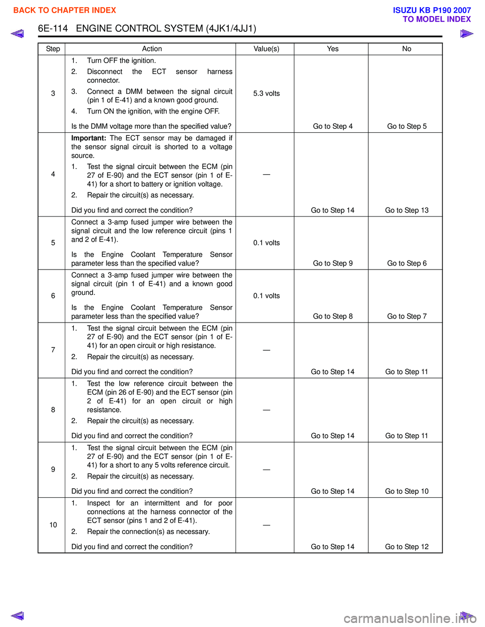
31. Turn OFF the ignition.
2. Disconnect the ECT sensor harness connector.
3. Connect a DMM between the signal circuit (pin 1 of E-41) and a known good ground.
4. Turn ON the ignition, with the engine OFF.
Is the DMM voltage more than the specified value? 5.3 volts
Go to Step 4 Go to Step 5
4 Important:
The ECT sensor may be damaged if
the sensor signal circuit is shorted to a voltage
source.
1. Test the signal circuit between the ECM (pin 27 of E-90) and the ECT sensor (pin 1 of E-
41) for a short to battery or ignition voltage.
2. Repair the circuit(s) as necessary.
Did you find and correct the condition? —
Go to Step 14 Go to Step 13
5 Connect a 3-amp fused jumper wire between the
signal circuit and the low reference circuit (pins 1
and 2 of E-41).
Is the Engine Coolant Temperature Sensor
parameter less than the specified value? 0.1 volts
Go to Step 9 Go to Step 6
6 Connect a 3-amp fused jumper wire between the
signal circuit (pin 1 of E-41) and a known good
ground.
Is the Engine Coolant Temperature Sensor
parameter less than the specified value? 0.1 volts
Go to Step 8 Go to Step 7
7 1. Test the signal circuit between the ECM (pin
27 of E-90) and the ECT sensor (pin 1 of E-
41) for an open circuit or high resistance.
2. Repair the circuit(s) as necessary.
Did you find and correct the condition? —
Go to Step 14 Go to Step 11
8 1. Test the low reference circuit between the
ECM (pin 26 of E-90) and the ECT sensor (pin
2 of E-41) for an open circuit or high
resistance.
2. Repair the circuit(s) as necessary.
Did you find and correct the condition? —
Go to Step 14 Go to Step 11
9 1. Test the signal circuit between the ECM (pin
27 of E-90) and the ECT sensor (pin 1 of E-
41) for a short to any 5 volts reference circuit.
2. Repair the circuit(s) as necessary.
Did you find and correct the condition? —
Go to Step 14 Go to Step 10
10 1. Inspect for an intermittent and for poor
connections at the harness connector of the
ECT sensor (pins 1 and 2 of E-41).
2. Repair the connection(s) as necessary.
Did you find and correct the condition? —
Go to Step 14 Go to Step 12
Step
Action Value(s)Yes No
BACK TO CHAPTER INDEX
TO MODEL INDEX
ISUZU KB P190 2007
Page 1733 of 6020
6E-116 ENGINE CONTROL SYSTEM (4JK1/4JJ1)
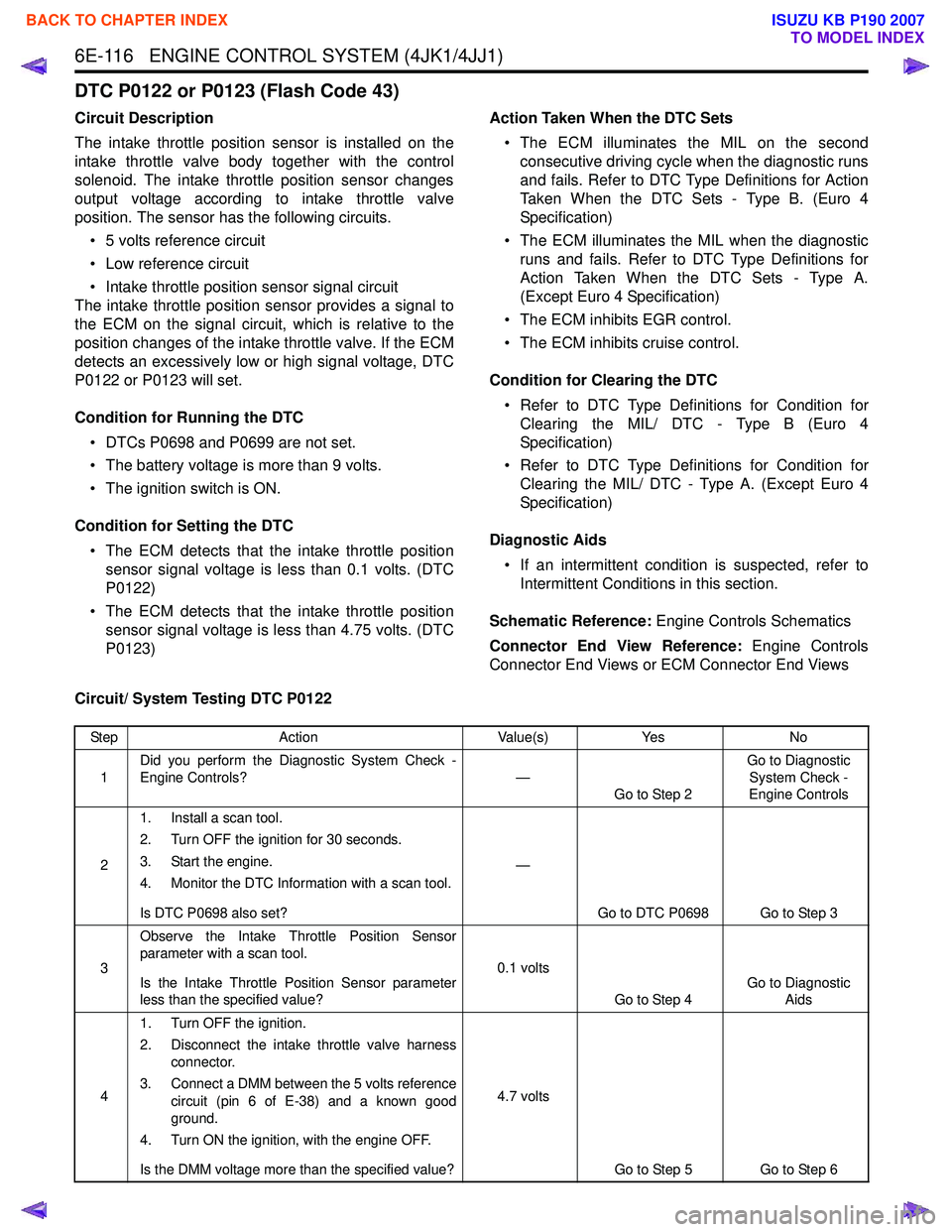
DTC P0122 or P0123 (Flash Code 43)
Circuit Description
The intake throttle position sensor is installed on the
intake throttle valve body together with the control
solenoid. The intake throttle position sensor changes
output voltage according to intake throttle valve
position. The sensor has the following circuits.
• 5 volts reference circuit
• Low reference circuit
• Intake throttle position sensor signal circuit
The intake throttle position sensor provides a signal to
the ECM on the signal circuit, which is relative to the
position changes of the intake throttle valve. If the ECM
detects an excessively low or high signal voltage, DTC
P0122 or P0123 will set.
Condition for Running the DTC • DTCs P0698 and P0699 are not set.
• The battery voltage is more than 9 volts.
• The ignition switch is ON.
Condition for Setting the DTC • The ECM detects that the intake throttle position sensor signal voltage is less than 0.1 volts. (DTC
P0122)
• The ECM detects that the intake throttle position sensor signal voltage is less than 4.75 volts. (DTC
P0123) Action Taken When the DTC Sets
• The ECM illuminates the MIL on the second consecutive driving cycle when the diagnostic runs
and fails. Refer to DTC Type Definitions for Action
Taken When the DTC Sets - Type B. (Euro 4
Specification)
• The ECM illuminates the MIL when the diagnostic runs and fails. Refer to DTC Type Definitions for
Action Taken When the DTC Sets - Type A.
(Except Euro 4 Specification)
• The ECM inhibits EGR control.
• The ECM inhibits cruise control.
Condition for Clearing the DTC • Refer to DTC Type Definitions for Condition for Clearing the MIL/ DTC - Type B (Euro 4
Specification)
• Refer to DTC Type Definitions for Condition for Clearing the MIL/ DTC - Type A. (Except Euro 4
Specification)
Diagnostic Aids • If an intermittent condition is suspected, refer to Intermittent Conditions in this section.
Schematic Reference: Engine Controls Schematics
Connector End View Reference: Engine Controls
Connector End Views or ECM Connector End Views
Circuit/ System Testing DTC P0122
Step Action Value(s)Yes No
1 Did you perform the Diagnostic System Check -
Engine Controls? —
Go to Step 2 Go to Diagnostic
System Check -
Engine Controls
2 1. Install a scan tool.
2. Turn OFF the ignition for 30 seconds.
3. Start the engine.
4. Monitor the DTC Information with a scan tool.
Is DTC P0698 also set? —
Go to DTC P0698 Go to Step 3
3 Observe the Intake Throttle Position Sensor
parameter with a scan tool.
Is the Intake Throttle Position Sensor parameter
less than the specified value? 0.1 volts
Go to Step 4 Go to Diagnostic
Aids
4 1. Turn OFF the ignition.
2. Disconnect the intake throttle valve harness connector.
3. Connect a DMM between the 5 volts reference circuit (pin 6 of E-38) and a known good
ground.
4. Turn ON the ignition, with the engine OFF.
Is the DMM voltage more than the specified value? 4.7 volts
Go to Step 5 Go to Step 6
BACK TO CHAPTER INDEX
TO MODEL INDEX
ISUZU KB P190 2007
Page 1734 of 6020
ENGINE CONTROL SYSTEM (4JK1/4JJ1) 6E-117
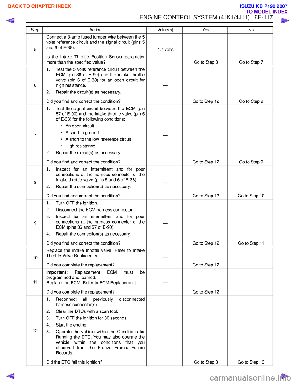
5Connect a 3-amp fused jumper wire between the 5
volts reference circuit and the signal circuit (pins 5
and 6 of E-38).
Is the Intake Throttle Position Sensor parameter
more than the specified value? 4.7 volts
Go to Step 8 Go to Step 7
6 1. Test the 5 volts reference circuit between the
ECM (pin 36 of E-90) and the intake throttle
valve (pin 6 of E-38) for an open circuit for
high resistance.
2. Repair the circuit(s) as necessary.
Did you find and correct the condition? —
Go to Step 12 Go to Step 9
7 1. Test the signal circuit between the ECM (pin
57 of E-90) and the intake throttle valve (pin 5
of E-38) for the following conditions:
• An open circuit
• A short to ground
• A short to the low reference circuit
• High resistance
2. Repair the circuit(s) as necessary.
Did you find and correct the condition? —
Go to Step 12 Go to Step 9
8 1. Inspect for an intermittent and for poor
connections at the harness connector of the
intake throttle valve (pins 5 and 6 of E-38).
2. Repair the connection(s) as necessary.
Did you find and correct the condition? —
Go to Step 12 Go to Step 10
9 1. Turn OFF the ignition.
2. Disconnect the ECM harness connector.
3. Inspect for an intermittent and for poor connections at the harness connector of the
ECM (pins 36 and 57 of E-90).
4. Repair the connection(s) as necessary.
Did you find and correct the condition? —
Go to Step 12 Go to Step 11
10 Replace the intake throttle valve. Refer to Intake
Throttle Valve Replacement.
Did you complete the replacement? —
Go to Step 12
—
11Important:
Replacement ECM must be
programmed and learned.
Replace the ECM. Refer to ECM Replacement.
Did you complete the replacement? —
Go to Step 12
—
121. Reconnect all previously disconnected
harness connector(s).
2. Clear the DTCs with a scan tool.
3. Turn OFF the ignition for 30 seconds.
4. Start the engine.
5. Operate the vehicle within the Conditions for Running the DTC. You may also operate the
vehicle within the conditions that you
observed from the Freeze Frame/ Failure
Records.
Did the DTC fail this ignition? —
Go to Step 3 Go to Step 13
Step
Action Value(s)Yes No
BACK TO CHAPTER INDEX
TO MODEL INDEX
ISUZU KB P190 2007
Page 1735 of 6020
6E-118 ENGINE CONTROL SYSTEM (4JK1/4JJ1)
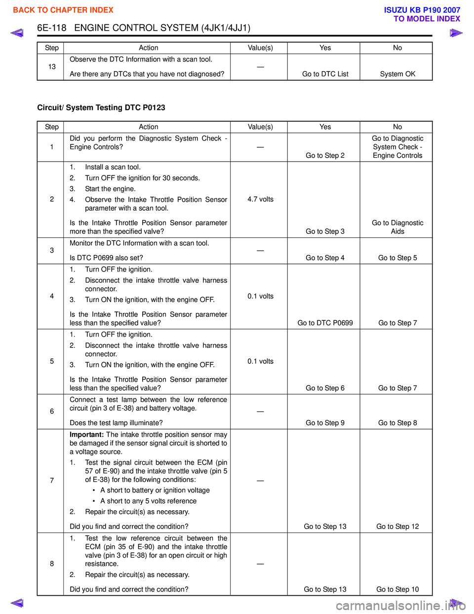
Circuit/ System Testing DTC P0123
13Observe the DTC Information with a scan tool.
Are there any DTCs that you have not diagnosed? —
Go to DTC List System OK
Step
Action Value(s)Yes No
Step Action Value(s)Yes No
1 Did you perform the Diagnostic System Check -
Engine Controls? —
Go to Step 2 Go to Diagnostic
System Check -
Engine Controls
2 1. Install a scan tool.
2. Turn OFF the ignition for 30 seconds.
3. Start the engine.
4. Observe the Intake Throttle Position Sensor parameter with a scan tool.
Is the Intake Throttle Position Sensor parameter
more than the specified valve? 4.7 volts
Go to Step 3 Go to Diagnostic
Aids
3 Monitor the DTC Information with a scan tool.
Is DTC P0699 also set? —
Go to Step 4 Go to Step 5
4 1. Turn OFF the ignition.
2. Disconnect the intake throttle valve harness connector.
3. Turn ON the ignition, with the engine OFF.
Is the Intake Throttle Position Sensor parameter
less than the specified value? 0.1 volts
Go to DTC P0699 Go to Step 7
5 1. Turn OFF the ignition.
2. Disconnect the intake throttle valve harness connector.
3. Turn ON the ignition, with the engine OFF.
Is the Intake Throttle Position Sensor parameter
less than the specified value? 0.1 volts
Go to Step 6 Go to Step 7
6 Connect a test lamp between the low reference
circuit (pin 3 of E-38) and battery voltage.
Does the test lamp illuminate? —
Go to Step 9 Go to Step 8
7 Important:
The intake throttle position sensor may
be damaged if the sensor signal circuit is shorted to
a voltage source.
1. Test the signal circuit between the ECM (pin 57 of E-90) and the intake throttle valve (pin 5
of E-38) for the following conditions:
• A short to battery or ignition voltage
• A short to any 5 volts reference
2. Repair the circuit(s) as necessary.
Did you find and correct the condition? —
Go to Step 13 Go to Step 12
8 1. Test the low reference circuit between the
ECM (pin 35 of E-90) and the intake throttle
valve (pin 3 of E-38) for an open circuit or high
resistance.
2. Repair the circuit(s) as necessary.
Did you find and correct the condition? —
Go to Step 13 Go to Step 10
BACK TO CHAPTER INDEX
TO MODEL INDEX
ISUZU KB P190 2007
Page 1737 of 6020
6E-120 ENGINE CONTROL SYSTEM (4JK1/4JJ1)
DTC P0182 or P0183 (Flash Code 211)
Circuit Description
The fuel temperature (FT) sensor is installed to the fuel
supply pump. The FT sensor is a variable resistor and it
measures the temperature of the fuel entering the fuel
supply pump. The sensor has a signal circuit and a low
reference circuit. The ECM supplies 5 volts to the
signal circuit and a ground for the low reference circuit.
When the FT sensor is cold, the sensor resistance is
high. When the fuel temperature increases, the sensor
resistance decreases. With high sensor resistance, the
ECM detects a high voltage on the signal circuit. With
lower sensor resistance, the ECM detects a lower
voltage on the signal circuit. If the ECM detects an
excessively low or high signal voltage, DTC P0182 or
P0183 will set.
Condition for Running the DTC • The battery voltage is more than 9 volts.
• The ignition switch is ON.
• The engine run time is longer than 3 minutes. (DTC P0183)
Condition for Setting the DTC • The ECM detects that the FT sensor signal voltage is less than 0.1 volts for 3 seconds. (DTC P0182)
• The ECM detects that the FT sensor signal voltage is more than 4.75 volts for 3 seconds. (DTC
P0183) Action Taken When the DTC Sets
• The ECM illuminates the MIL when the diagnostic runs and fails. Refer to DTC Type Definitions for
Action Taken When the DTC Sets - Type A.
• The ECM uses a FT substitution of default value.
• The ECM limits fuel injection quantity.
• The ECM inhibits pilot injection.
• The ECM inhibits cruise control.
Condition for Clearing the DTC • Refer to DTC Type Definitions for Condition for Clearing the MIL/ DTC - Type A.
Diagnostic Aids • Before starting a cold engine, FT sensor and engine coolant temperature (ECT) sensor
temperature should be relatively close to each
other.
• If an intermittent condition is suspected, refer to Intermittent Conditions in this section.
• Use the Temperature vs. Resistance table to test the FT sensor at various temperature levels to
evaluate the possibility of a skewed sensor. A
skewed sensor could result in poor driveability
concerns.
Schematic Reference: Engine Controls Schematics
Connector End View Reference: Engine Controls
Connector End Views or ECM Connector End Views
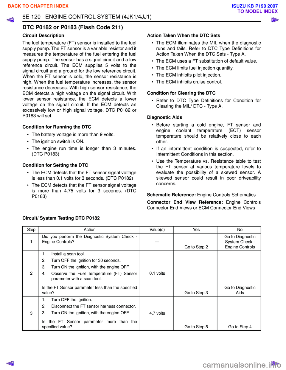
Circuit/ System Testing DTC P0182
Step Action Value(s)Yes No
1 Did you perform the Diagnostic System Check -
Engine Controls? —
Go to Step 2 Go to Diagnostic
System Check -
Engine Controls
2 1. Install a scan tool.
2. Turn OFF the ignition for 30 seconds.
3. Turn ON the ignition, with the engine OFF.
4. Observe the Fuel Temperature (FT) Sensor parameter with a scan tool.
Is the FT Sensor parameter less than the specified
value? 0.1 volts
Go to Step 3 Go to Diagnostic
Aids
3 1. Turn OFF the ignition.
2. Disconnect the FT sensor harness connector.
3. Turn ON the ignition, with the engine OFF.
Is the FT Sensor parameter more than the
specified value? 4.7 volts
Go to Step 5 Go to Step 4
BACK TO CHAPTER INDEX
TO MODEL INDEX
ISUZU KB P190 2007
Page 1738 of 6020
ENGINE CONTROL SYSTEM (4JK1/4JJ1) 6E-121
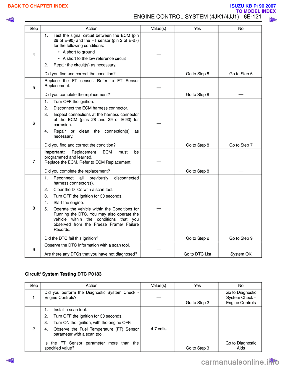
Circuit/ System Testing DTC P0183
41. Test the signal circuit between the ECM (pin
29 of E-90) and the FT sensor (pin 2 of E-27)
for the following conditions:
• A short to ground
• A short to the low reference circuit
2. Repair the circuit(s) as necessary.
Did you find and correct the condition? —
Go to Step 8 Go to Step 6
5 Replace the FT sensor. Refer to FT Sensor
Replacement.
Did you complete the replacement? —
Go to Step 8
—
61. Turn OFF the ignition.
2. Disconnect the ECM harness connector.
3. Inspect connections at the harness connector of the ECM (pins 28 and 29 of E-90) for
corrosion.
4. Repair or clean the connection(s) as necessary.
Did you find and correct the condition? —
Go to Step 8 Go to Step 7
7 Important:
Replacement ECM must be
programmed and learned.
Replace the ECM. Refer to ECM Replacement.
Did you complete the replacement? —
Go to Step 8
—
81. Reconnect all previously disconnected
harness connector(s).
2. Clear the DTCs with a scan tool.
3. Turn OFF the ignition for 30 seconds.
4. Start the engine.
5. Operate the vehicle within the Conditions for Running the DTC. You may also operate the
vehicle within the conditions that you
observed from the Freeze Frame/ Failure
Records.
Did the DTC fail this ignition? —
Go to Step 2 Go to Step 9
9 Observe the DTC Information with a scan tool.
Are there any DTCs that you have not diagnosed? —
Go to DTC List System OK
Step
Action Value(s)Yes No
Step Action Value(s)Yes No
1 Did you perform the Diagnostic System Check -
Engine Controls? —
Go to Step 2 Go to Diagnostic
System Check -
Engine Controls
2 1. Install a scan tool.
2. Turn OFF the ignition for 30 seconds.
3. Turn ON the ignition, with the engine OFF.
4. Observe the Fuel Temperature (FT) Sensor parameter with a scan tool.
Is the FT Sensor parameter more than the
specified value? 4.7 volts
Go to Step 3 Go to Diagnostic
Aids
BACK TO CHAPTER INDEX
TO MODEL INDEX
ISUZU KB P190 2007
Page 1739 of 6020
6E-122 ENGINE CONTROL SYSTEM (4JK1/4JJ1)
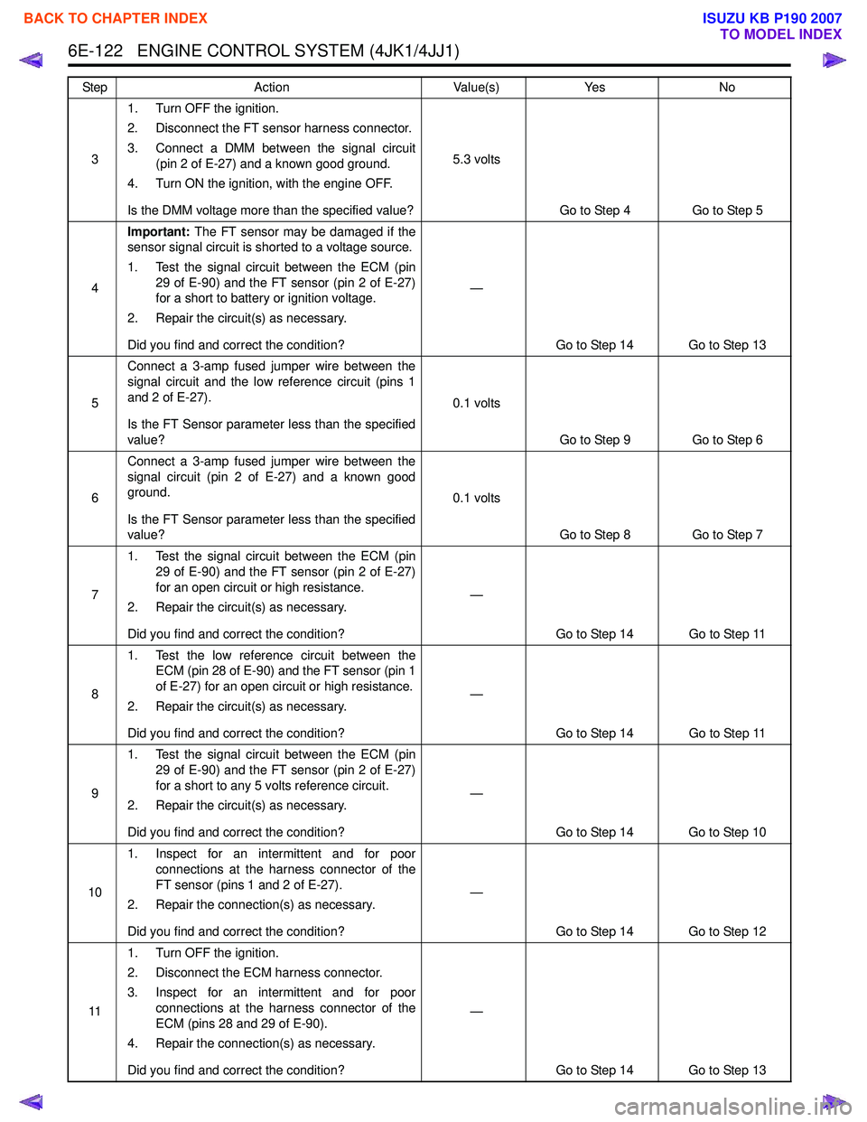
31. Turn OFF the ignition.
2. Disconnect the FT sensor harness connector.
3. Connect a DMM between the signal circuit (pin 2 of E-27) and a known good ground.
4. Turn ON the ignition, with the engine OFF.
Is the DMM voltage more than the specified value? 5.3 volts
Go to Step 4 Go to Step 5
4 Important:
The FT sensor may be damaged if the
sensor signal circuit is shorted to a voltage source.
1. Test the signal circuit between the ECM (pin 29 of E-90) and the FT sensor (pin 2 of E-27)
for a short to battery or ignition voltage.
2. Repair the circuit(s) as necessary.
Did you find and correct the condition? —
Go to Step 14 Go to Step 13
5 Connect a 3-amp fused jumper wire between the
signal circuit and the low reference circuit (pins 1
and 2 of E-27).
Is the FT Sensor parameter less than the specified
value? 0.1 volts
Go to Step 9 Go to Step 6
6 Connect a 3-amp fused jumper wire between the
signal circuit (pin 2 of E-27) and a known good
ground.
Is the FT Sensor parameter less than the specified
value? 0.1 volts
Go to Step 8 Go to Step 7
7 1. Test the signal circuit between the ECM (pin
29 of E-90) and the FT sensor (pin 2 of E-27)
for an open circuit or high resistance.
2. Repair the circuit(s) as necessary.
Did you find and correct the condition? —
Go to Step 14 Go to Step 11
8 1. Test the low reference circuit between the
ECM (pin 28 of E-90) and the FT sensor (pin 1
of E-27) for an open circuit or high resistance.
2. Repair the circuit(s) as necessary.
Did you find and correct the condition? —
Go to Step 14 Go to Step 11
9 1. Test the signal circuit between the ECM (pin
29 of E-90) and the FT sensor (pin 2 of E-27)
for a short to any 5 volts reference circuit.
2. Repair the circuit(s) as necessary.
Did you find and correct the condition? —
Go to Step 14 Go to Step 10
10 1. Inspect for an intermittent and for poor
connections at the harness connector of the
FT sensor (pins 1 and 2 of E-27).
2. Repair the connection(s) as necessary.
Did you find and correct the condition? —
Go to Step 14 Go to Step 12
11 1. Turn OFF the ignition.
2. Disconnect the ECM harness connector.
3. Inspect for an intermittent and for poor connections at the harness connector of the
ECM (pins 28 and 29 of E-90).
4. Repair the connection(s) as necessary.
Did you find and correct the condition? —
Go to Step 14 Go to Step 13
Step
Action Value(s)Yes No
BACK TO CHAPTER INDEX
TO MODEL INDEX
ISUZU KB P190 2007