2007 ISUZU KB P190 wheel alignment
[x] Cancel search: wheel alignmentPage 573 of 6020

FRONT WHEEL DRIVE 4C1-69
6. FRONT WHEEL SHIMMY
Checkpoint Trouble Cause Countermeasure
Ball joint or bush
Replace the ball joint or bush
Worn
Front alignment
Adjust the front alignment
Adjust or replace
Incorrect
W orn or improperly adjusted
OK
OK NG
NG
NG
OK
W heel bearing
Tighten or replace
Loose or worn
NG
Shock absorber
Replace the shock absorber
Worn
Tire
Replace or adjust the inflation
W orn or improperly inflated
OK NG
NG
OK
Steering unit
BACK TO CHAPTER INDEX
TO MODEL INDEX
ISUZU KB P190 2007
Page 3391 of 6020

Engine Management – V6 – Diagnostics Page 6C1-2–113
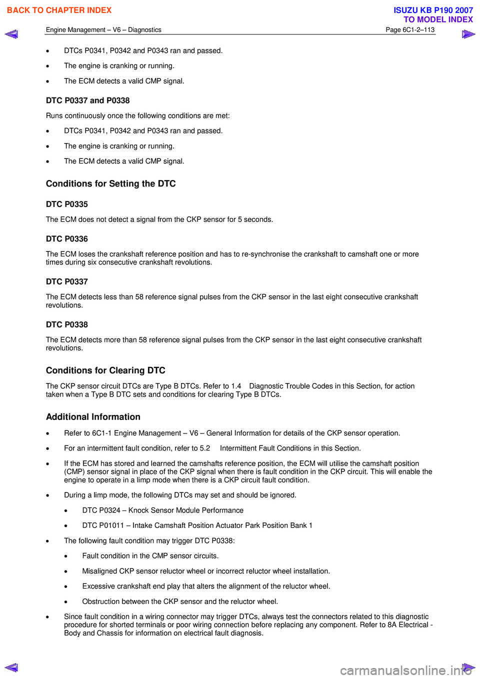
• DTCs P0341, P0342 and P0343 ran and passed.
• The engine is cranking or running.
• The ECM detects a valid CMP signal.
DTC P0337 and P0338
Runs continuously once the following conditions are met:
• DTCs P0341, P0342 and P0343 ran and passed.
• The engine is cranking or running.
• The ECM detects a valid CMP signal.
Conditions for Setting the DTC
DTC P0335
The ECM does not detect a signal from the CKP sensor for 5 seconds.
DTC P0336
The ECM loses the crankshaft reference position and has to re-synchronise the crankshaft to camshaft one or more
times during six consecutive crankshaft revolutions.
DTC P0337
The ECM detects less than 58 reference signal pulses from the CKP sensor in the last eight consecutive crankshaft
revolutions.
DTC P0338
The ECM detects more than 58 reference signal pulses from the CKP sensor in the last eight consecutive crankshaft
revolutions.
Conditions for Clearing DTC
The CKP sensor circuit DTCs are Type B DTCs. Refer to 1.4 Diagnostic Trouble Codes in this Section, for action
taken when a Type B DTC sets and conditions for clearing Type B DTCs.
Additional Information
• Refer to 6C1-1 Engine Management – V6 – General Information for details of the CKP sensor operation.
• For an intermittent fault condition, refer to 5.2 Intermittent Fault Conditions in this Section.
• If the ECM has stored and learned the camshafts reference position, the ECM will utilise the camshaft position
(CMP) sensor signal in place of the CKP signal when there is fault condition in the CKP circuit. This will enable the
engine to operate in a limp mode when there is a CKP circuit fault condition.
• During a limp mode, the following DTCs may set and should be ignored.
• DTC P0324 – Knock Sensor Module Performance
• DTC P01011 – Intake Camshaft Position Actuator Park Position Bank 1
• The following fault condition may trigger DTC P0338:
• Fault condition in the CMP sensor circuits.
• Misaligned CKP sensor reluctor wheel or incorrect reluctor wheel installation.
• Excessive crankshaft end play that alters the alignment of the reluctor wheel.
• Obstruction between the CKP sensor and the reluctor wheel.
• Since fault condition in a wiring connector may trigger DTCs, always test the connectors related to this diagnostic
procedure for shorted terminals or poor wiring connection before replacing any component. Refer to 8A Electrical -
Body and Chassis for information on electrical fault diagnosis.
BACK TO CHAPTER INDEX
TO MODEL INDEX
ISUZU KB P190 2007
Page 3395 of 6020

Engine Management – V6 – Diagnostics Page 6C1-2–117
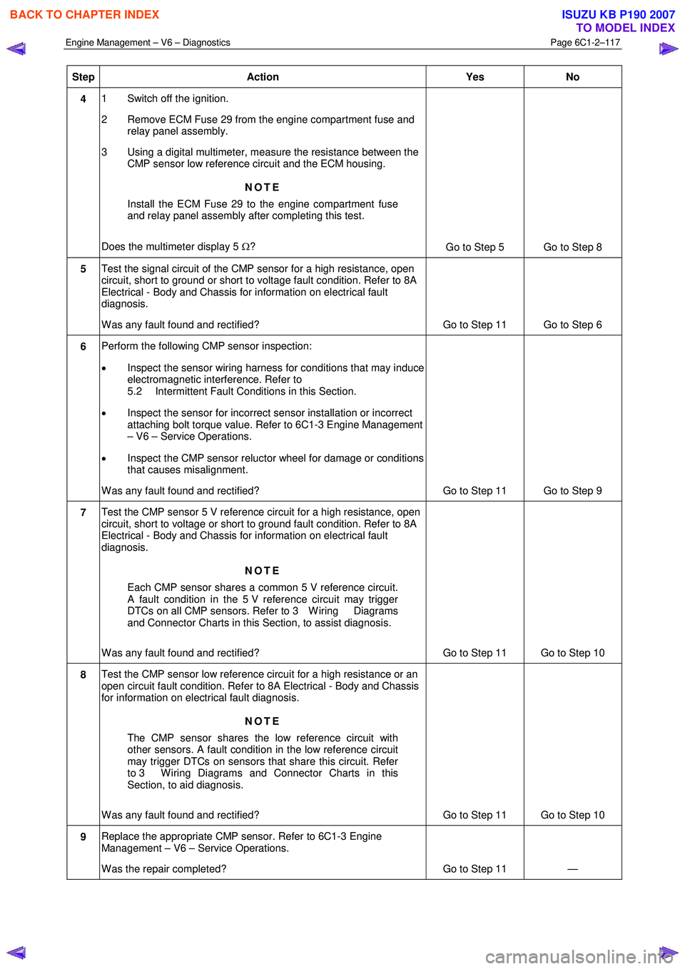
Step Action Yes No
4 1 Switch off the ignition.
2 Remove ECM Fuse 29 from the engine compartment fuse and relay panel assembly.
3 Using a digital multimeter, measure the resistance between the CMP sensor low reference circuit and the ECM housing.
NOTE
Install the ECM Fuse 29 to the engine compartment fuse
and relay panel assembly after completing this test.
Does the multimeter display 5 Ω?
Go to Step 5 Go to Step 8
5 Test the signal circuit of the CMP sensor for a high resistance, open
circuit, short to ground or short to voltage fault condition. Refer to 8A
Electrical - Body and Chassis for information on electrical fault
diagnosis.
W as any fault found and rectified? Go to Step 11 Go to Step 6
6 Perform the following CMP sensor inspection:
• Inspect the sensor wiring harness for conditions that may induce
electromagnetic interference. Refer to
5.2 Intermittent Fault Conditions in this Section.
• Inspect the sensor for incorrect sensor installation or incorrect
attaching bolt torque value. Refer to 6C1-3 Engine Management
– V6 – Service Operations.
• Inspect the CMP sensor reluctor wheel for damage or conditions
that causes misalignment.
W as any fault found and rectified? Go to Step 11 Go to Step 9
7 Test the CMP sensor 5 V reference circuit for a high resistance, open
circuit, short to voltage or short to ground fault condition. Refer to 8A
Electrical - Body and Chassis for information on electrical fault
diagnosis.
NOTE
Each CMP sensor shares a common 5 V reference circuit.
A fault condition in the 5 V reference circuit may trigger
DTCs on all CMP sensors. Refer to 3 W iring Diagrams
and Connector Charts in this Section, to assist diagnosis.
W as any fault found and rectified? Go to Step 11 Go to Step 10
8 Test the CMP sensor low reference circuit for a high resistance or an
open circuit fault condition. Refer to 8A Electrical - Body and Chassis
for information on electrical fault diagnosis.
NOTE
The CMP sensor shares the low reference circuit with
other sensors. A fault condition in the low reference circuit
may trigger DTCs on sensors that share this circuit. Refer
to 3 W iring Diagrams and Connector Charts in this
Section, to aid diagnosis.
W as any fault found and rectified? Go to Step 11 Go to Step 10
9 Replace the appropriate CMP sensor. Refer to 6C1-3 Engine
Management – V6 – Service Operations.
W as the repair completed? Go to Step 11 —
BACK TO CHAPTER INDEX
TO MODEL INDEX
ISUZU KB P190 2007
Page 3410 of 6020

Engine Management – V6 – Diagnostics Page 6C1-2–132
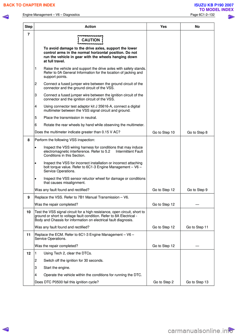
Step Action Yes No
7
To avoid damage to the drive axles, support the lower
control arms in the normal horizontal position. Do not
run the vehicle in gear with the wheels hanging down
at full travel.
1 Raise the vehicle and support the drive axles with safety stands. Refer to 0A General Information for the location of jacking and
support points.
2 Connect a fused jumper wire between the ground circuit of the connector and the ground circuit of the VSS.
3 Connect a fused jumper wire between the ignition circuit of the connector and the ignition circuit of the VSS.
4 Using connector test adaptor kit J 35616-A, connect a digital multimeter between the VSS signal circuit and ground.
5 Place the transmission in neutral.
6 Rotate the rear wheels by hand while observing the multimeter.
Does the multimeter indicate greater than 0.15 V AC? Go to Step 10 Go to Step 8
8 Perform the following VSS inspection:
• Inspect the VSS wiring harness for conditions that may induce
electromagnetic interference. Refer to 5.2 Intermittent Fault
Conditions in this Section.
• Inspect the VSS for incorrect installation or incorrect attaching
bolt torque value. Refer to 6C1-3 Engine Management – V6 –
Service Operations.
• Inspect the VSS sensor reluctor wheel for damage or conditions
that causes misalignment.
W as any fault found and rectified? Go to Step 12 Go to Step 9
9 Replace the VSS. Refer to 7B1 Manual Transmission – V6.
W as the repair completed? Go to Step 12 —
10 Test the VSS signal circuit for a high resistance, open circuit, short to
ground or short to voltage fault condition. Refer to 8A Electrical -
Body and Chassis for information on electrical fault diagnosis.
W as any fault found and rectified? Go to Step 12 Go to Step 11
11 Replace the ECM. Refer to 6C1-3 Engine Management – V6 –
Service Operations.
W as the repair completed? Go to Step 12 —
12 1 Using Tech 2, clear the DTCs.
2 Switch off the ignition for 30 seconds.
3 Start the engine.
4 Operate the vehicle within the conditions for running the DTC.
Does DTC P0500 fail this ignition cycle? Go to Step 2 Go to Step 13
BACK TO CHAPTER INDEX
TO MODEL INDEX
ISUZU KB P190 2007
Page 4657 of 6020

MANUAL TRANSMISSION 7B1-51
TROUBLESHOOTING
1. ABNORMAL NOISE
1) NOISY IN NEUTRAL
Checkpoint Trouble Cause Countermeasure
Replenish or replace the gear
oilInsufficient or improper gear
oil
NG
Mainshaft splines
Synchronizer clutch hub
splinesReplace the main shaft and
the synchronizer clutch hub
Replace the gear(s)
Replace the flywheel pilot
W orn splines
W orn or scuffed gear tooth
contact surfaces
Flywheel pilot bearingW orn flywheel pilot bearing
Bearings (Mainshaft,
countershaft, and transfer
shaft)
Gears (Mainshaft,
countershaft, reverse idler
gear and transfer gears)
Replace the bearing(s)W orn or broken bearing(s)
OK NG
NG
NG
NG
OK
OK
OK
Gear oil
TransmissionRealign the transmissionTransmission misalignment
OK
NG
BACK TO CHAPTER INDEX
TO MODEL INDEX
ISUZU KB P190 2007
Page 4711 of 6020

MANUAL TRANSMISSION 7B1-105
TROUBLESHOOTING
1. ABNORMAL NOISE
1) NOISY IN NEUTRAL
Checkpoint Trouble Cause Countermeasure
Replenish or replace the gear
oilInsufficient or improper gear
oil
NG
Mainshaft splines
Synchronizer clutch hub
splinesReplace the main shaft and
the synchronizer clutch hub
Replace the gear(s)
Replace the flywheel pilot
W orn splines
W orn or scuffed gear tooth
contact surfaces
Flywheel pilot bearingW orn flywheel pilot bearing
Bearings (Mainshaft,
countershaft, and transfer
shaft)
Gears (Mainshaft,
countershaft, reverse idler
gear and transfer gears)
Replace the bearing(s)W orn or broken bearing(s)
OK NG
NG
NG
NG
OK
OK
OK
Gear oil
TransmissionRealign the transmissionTransmission misalignment
OK
NG
BACK TO CHAPTER INDEX
TO MODEL INDEX
ISUZU KB P190 2007
Page 4723 of 6020

7B1-4 Manual Transmission (MUX)
Troubleshooting
ConditionPossible Cause Correction
Abnormal Noise (Noisy in Neutral) Insufficient or improper lubricant Replenish or replace lubricant Flywheel pilot bearing worn or
broken Replace flywheel pilot bearing
Bearing(s) worn or broken (Input
shaft, counter shaft, and output
shaft) Replace bearing(s)
Gear tooth contact surfaces worn or
scuffed (Input shaft, counter shaft,
output shaft, and reverse idler gear) Replace gear(s)
Spline worn (Input shaft, output
shaft, counter shaft, and
synchronizer clutch hub) Replace worn parts
Transmission misalignment Realign transmission
Abnormal Noise (Noisy Operation) Insufficient or improper lubricant (Metallic rattling) Replenish or replace lubricant
Bearing(s) worn or broken (Hissing,
thumping, or bumping) Replace bearing(s)
Gear(s) worn, chipped, or cracked
(Growling, humming, or grinding) Replace gear(s)
Gears seizing on thrust face or
inner face free running (Squealing
at high speeds) Replace gear(s)
Gears lack of backlash between
meshing (Gear whining) Replace gear(s)
Hard Shifting Insufficient or improper lubricant Replenish or replace lubricant
Improper clutch pedal free play Readjust clutch pedal free play
Hard operating of change lever
caused insufficient grease Repair or regrease change lever
assembly
Change lever sliding portions worn Repair or replace applicable parts and regrease
Shift block sleeve movement failure Repair or replace sleeve
Shift rod and/or quadrant box
sliding face worn Replace worn parts
Shift arm and/or synchronizer
sleeve groove worn Replace worn parts
Collar, and/or gear thrust faces
worn (Input shaft and counter shaft
thrust play) Replace worn parts
Synchronizer parts worn Replace worn parts
BACK TO CHAPTER INDEX
TO MODEL INDEX
ISUZU KB P190 2007