2007 ISUZU KB P190 transmission oil
[x] Cancel search: transmission oilPage 1938 of 6020

ENGINE CONTROL SYSTEM (4JK1/4JJ1) 6E-321
31. Inspect the following conditions:
• Air leakage around the boost pressuresensor objects that block the sensor hole.
• Air leaking around any of the air induction tubing between the turbocharger and
intake manifold. Check for damaged
components and for loose clamps.
• Misrouted, disconnected or kinked turbocharger nozzle control actuator
vacuum hoses. Refer to Vacuum Hose
Routing Diagram in this section for
correct routing.
• Turbine shaft binding causing lower turbocharger spinning speeds. Refer to
the Turbocharger in engine mechanical
section for diagnosis.
• Turbocharger nozzle control actuator for a stuck condition or slow movement.
Refer to Turbocharger in engine
mechanical section for testing.
• Intake throttle valve sticking. Perform the Intake Throttle Solenoid Control with a
scan tool.
• Restricted air cleaner element, restricted or collapsed air tubing between the air
cleaner and the boost pressure sensor.
• Oil in the air induction tubing causing an incorrect boost pressure sensor signal.
When there is adhesion of oil inside of
tubing, intercooler or turbocharger it
needs to be wiped off.
2. Repair the condition as necessary.
Did you find and correct the condition? —
Go to Step 8 Go to Step 4
4 1. Place the transmission in Neutral and set the
parking brake.
2. Accelerate the engine between idle and W.O.T. (accelerator pedal full travel) many
times while observing the Desired Boost
Pressure and Boost Pressure parameter with
a scan tool.
3. Drive the vehicle that the engine speed is more than 2000 RPM and the Calculated
Engine Load parameter reaches at least 50%
for longer than 10 seconds (such as
acceleration on ramp) while comparing the
Boost Pressure to the Desired Boost
Pressure.
Does the Boost Pressure parameter follow within
the specified value? ±
20 kPa ( ±3
psi)
System OK Go to Step 5
Step
Action Value(s)Yes No
BACK TO CHAPTER INDEX
TO MODEL INDEX
ISUZU KB P190 2007
Page 1953 of 6020
6E-336 ENGINE CONTROL SYSTEM (4JK1/4JJ1)
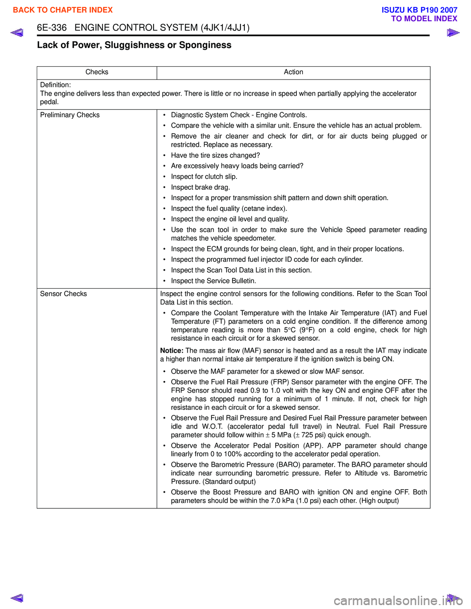
Lack of Power, Sluggishness or Sponginess
ChecksAction
Definition:
The engine delivers less than expected power. There is little or no increase in speed when partially applying the accelerator
pedal.
Preliminary Checks • Diagnostic System Check - Engine Controls.
• Compare the vehicle with a similar unit. Ensure the vehicle has an actual problem.
• Remove the air cleaner and check for dirt, or for air ducts being plugged or restricted. Replace as necessary.
• Have the tire sizes changed?
• Are excessively heavy loads being carried?
• Inspect for clutch slip.
• Inspect brake drag.
• Inspect for a proper transmission shift pattern and down shift operation.
• Inspect the fuel quality (cetane index).
• Inspect the engine oil level and quality.
• Use the scan tool in order to make sure the Vehicle Speed parameter reading matches the vehicle speedometer.
• Inspect the ECM grounds for being clean, tight, and in their proper locations.
• Inspect the programmed fuel injector ID code for each cylinder.
• Inspect the Scan Tool Data List in this section.
• Inspect the Service Bulletin.
Sensor Checks Inspect the engine control sensors for the following conditions. Refer to the Scan Tool
Data List in this section.
• Compare the Coolant Temperature with the Intake Air Temperature (IAT) and Fuel Temperature (FT) parameters on a cold engine condition. If the difference among
temperature reading is more than 5 °C (9 °F) on a cold engine, check for high
resistance in each circuit or for a skewed sensor.
Notice: The mass air flow (MAF) sensor is heated and as a result the IAT may indicate
a higher than normal intake air temperature if the ignition switch is being ON.
• Observe the MAF parameter for a skewed or slow MAF sensor.
• Observe the Fuel Rail Pressure (FRP) Sensor parameter with the engine OFF. The FRP Sensor should read 0.9 to 1.0 volt with the key ON and engine OFF after the
engine has stopped running for a minimum of 1 minute. If not, check for high
resistance in each circuit or for a skewed sensor.
• Observe the Fuel Rail Pressure and Desired Fuel Rail Pressure parameter between idle and W.O.T. (accelerator pedal full travel) in Neutral. Fuel Rail Pressure
parameter should follow within ± 5 MPa ( ± 725 psi) quick enough.
• Observe the Accelerator Pedal Position (APP). APP parameter should change linearly from 0 to 100% according to the accelerator pedal operation.
• Observe the Barometric Pressure (BARO) parameter. The BARO parameter should indicate near surrounding barometric pressure. Refer to Altitude vs. Barometric
Pressure. (Standard output)
• Observe the Boost Pressure and BARO with ignition ON and engine OFF. Both parameters should be within the 7.0 kPa (1.0 psi) each other. (High output)
BACK TO CHAPTER INDEX
TO MODEL INDEX
ISUZU KB P190 2007
Page 1955 of 6020
6E-338 ENGINE CONTROL SYSTEM (4JK1/4JJ1)
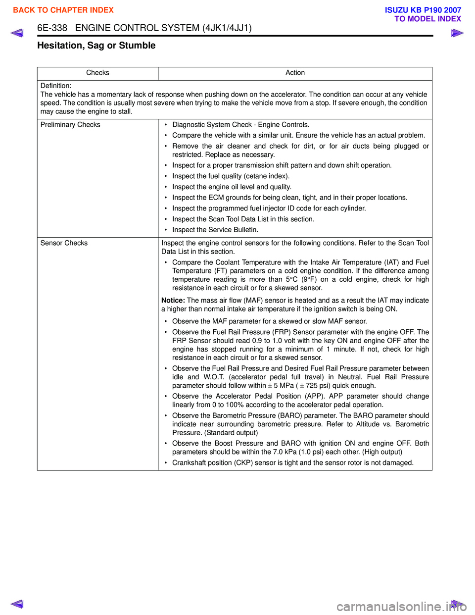
Hesitation, Sag or Stumble
ChecksAction
Definition:
The vehicle has a momentary lack of response when pushing down on the accelerator. The condition can occur at any vehicle
speed. The condition is usually most severe when trying to make the vehicle move from a stop. If severe enough, the condition
may cause the engine to stall.
Preliminary Checks • Diagnostic System Check - Engine Controls.
• Compare the vehicle with a similar unit. Ensure the vehicle has an actual problem.
• Remove the air cleaner and check for dirt, or for air ducts being plugged or restricted. Replace as necessary.
• Inspect for a proper transmission shift pattern and down shift operation.
• Inspect the fuel quality (cetane index).
• Inspect the engine oil level and quality.
• Inspect the ECM grounds for being clean, tight, and in their proper locations.
• Inspect the programmed fuel injector ID code for each cylinder.
• Inspect the Scan Tool Data List in this section.
• Inspect the Service Bulletin.
Sensor Checks Inspect the engine control sensors for the following conditions. Refer to the Scan Tool
Data List in this section.
• Compare the Coolant Temperature with the Intake Air Temperature (IAT) and Fuel Temperature (FT) parameters on a cold engine condition. If the difference among
temperature reading is more than 5 °C (9 °F) on a cold engine, check for high
resistance in each circuit or for a skewed sensor.
Notice: The mass air flow (MAF) sensor is heated and as a result the IAT may indicate
a higher than normal intake air temperature if the ignition switch is being ON.
• Observe the MAF parameter for a skewed or slow MAF sensor.
• Observe the Fuel Rail Pressure (FRP) Sensor parameter with the engine OFF. The FRP Sensor should read 0.9 to 1.0 volt with the key ON and engine OFF after the
engine has stopped running for a minimum of 1 minute. If not, check for high
resistance in each circuit or for a skewed sensor.
• Observe the Fuel Rail Pressure and Desired Fuel Rail Pressure parameter between idle and W.O.T. (accelerator pedal full travel) in Neutral. Fuel Rail Pressure
parameter should follow within ± 5 MPa ( ± 725 psi) quick enough.
• Observe the Accelerator Pedal Position (APP). APP parameter should change linearly from 0 to 100% according to the accelerator pedal operation.
• Observe the Barometric Pressure (BARO) parameter. The BARO parameter should indicate near surrounding barometric pressure. Refer to Altitude vs. Barometric
Pressure. (Standard output)
• Observe the Boost Pressure and BARO with ignition ON and engine OFF. Both parameters should be within the 7.0 kPa (1.0 psi) each other. (High output)
• Crankshaft position (CKP) sensor is tight and the sensor rotor is not damaged.
BACK TO CHAPTER INDEX
TO MODEL INDEX
ISUZU KB P190 2007
Page 1958 of 6020
ENGINE CONTROL SYSTEM (4JK1/4JJ1) 6E-341
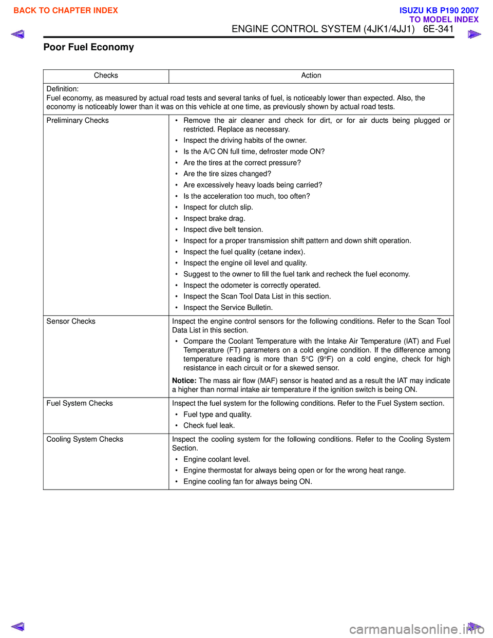
Poor Fuel Economy
ChecksAction
Definition:
Fuel economy, as measured by actual road tests and several tanks of fuel, is noticeably lower than expected. Also, the
economy is noticeably lower than it was on this vehicle at one time, as previously shown by actual road tests.
Preliminary Checks • Remove the air cleaner and check for dirt, or for air ducts being plugged or
restricted. Replace as necessary.
• Inspect the driving habits of the owner.
• Is the A/C ON full time, defroster mode ON?
• Are the tires at the correct pressure?
• Are the tire sizes changed?
• Are excessively heavy loads being carried?
• Is the acceleration too much, too often?
• Inspect for clutch slip.
• Inspect brake drag.
• Inspect dive belt tension.
• Inspect for a proper transmission shift pattern and down shift operation.
• Inspect the fuel quality (cetane index).
• Inspect the engine oil level and quality.
• Suggest to the owner to fill the fuel tank and recheck the fuel economy.
• Inspect the odometer is correctly operated.
• Inspect the Scan Tool Data List in this section.
• Inspect the Service Bulletin.
Sensor Checks Inspect the engine control sensors for the following conditions. Refer to the Scan Tool
Data List in this section.
• Compare the Coolant Temperature with the Intake Air Temperature (IAT) and Fuel Temperature (FT) parameters on a cold engine condition. If the difference among
temperature reading is more than 5 °C (9 °F) on a cold engine, check for high
resistance in each circuit or for a skewed sensor.
Notice: The mass air flow (MAF) sensor is heated and as a result the IAT may indicate
a higher than normal intake air temperature if the ignition switch is being ON.
Fuel System Checks Inspect the fuel system for the following conditions. Refer to the Fuel System section.
• Fuel type and quality.
• Check fuel leak.
Cooling System Checks Inspect the cooling system for the following conditions. Refer to the Cooling System
Section.
• Engine coolant level.
• Engine thermostat for always being open or for the wrong heat range.
• Engine cooling fan for always being ON.
BACK TO CHAPTER INDEX
TO MODEL INDEX
ISUZU KB P190 2007
Page 2012 of 6020
6-12 ENGINE DIAGNOSIS (C24SE)
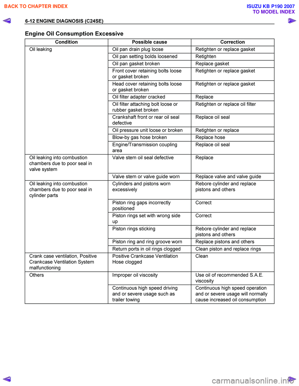
Engine Oil Consumption Excessive
Condition Possible cause Correction
Oil leaking Oil pan drain plug loose Retighten or replace gasket
Oil pan setting bolds loosened Retighten
Oil pan gasket broken Replace gasket
Front cover retaining bolts loose
or gasket broken Retighten or replace gasket
Head cover retaining bolts loose
or gasket broken Retighten or replace gasket
Oil filter adapter cracked Replace
Oil filter attaching bolt loose or
rubber gasket broken Retighten or replace oil filter
Crankshaft front or rear oil seal
defective Replace oil seal
Oil pressure unit loose or broken Retighten or replace
Blow-by gas hose broken Replace hose
Engine/Transmission coupling
area Replace oil seal
Oil leaking into combustion
chambers due to poor seal in
valve system Valve stem oil seal defective Replace
Valve stem or valve guide worn Replace valve and valve guide
Oil leaking into combustion
chambers due to poor seal in
cylinder parts Cylinders and pistons worn
excessively Rebore cylinder and replace
pistons and others
Piston ring gaps incorrectly
positioned Correct
Piston rings set with wrong side
up Correct
Piston rings sticking Rebore cylinder and replace
pistons and others
Piston ring and ring groove worn Replace pistons and others
Return ports in oil rings clogged Clean piston and replace rings
Crank case ventilation, Positive
Crankcase Ventilation System
malfunctioning Positive Crankcase Ventilation
Hose clogged Clean
Others
Improper oil viscosity Use oil of recommended S.A.E.
viscosity
Continuous high speed driving
and or severe usage such as
trailer towing Continuous high speed operation
and or severe usage will normally
cause increased oil consumption
BACK TO CHAPTER INDEX
TO MODEL INDEX
ISUZU KB P190 2007
Page 2013 of 6020
ENGINE DIAGNOSIS (C24SE) 6-13
Fuel Consumption Excessive
Condition Possible cause Correction
Trouble in fuel system Mixture too rich or too lean due to
trouble in fuel injection system Refer to "Abnormal Combustion"
Fuel cut function does not act Refer to "Abnormal Combustion"
Trouble in ignition system Misfiring or abnormal combustion
due to trouble in ignition system Refer to Hard Start or Abnormal
Combustion Troubleshooting
Guide
Others Engine idle speed too high Reset Idle Air Control Valve
Returning of accelerator control
sluggish Correct
Fuel system leakage Correct or replace
Clutch slipping Correct
Brake drag Correct
Selection of transmission gear
incorrect Caution operator of incorrect gear
selection
Oil Problems
Condition Possible cause Correction
Oil pressure too low Wrong oil in use Replace with correct engine oil
Relief valve sticking Replace
Oil pump not operating properly Correct or replace
Oil pump strainer clogged Clean or replace strainer
Oil pump worn Replace
Oil pressure gauge defective Correct or replace
Crankshaft bearing or connecting
rod bearing worn Replace
Oil contamination
Wrong oil in use Replace with new engine oil
Oil filter clogged Replace oil filter
Cylinder head gasket damage Replace gasket
Burned gases leaking Replace piston and piston rings or
rebore cylinders
Oil not reaching valve system Oil passage in cylinder head or cylinder body clogged Clean or correct
Engine Oil Pressure Check
1. Check for dirt, gasoline or water in the engine
oil.
a. Check the viscosity of the oil.
b. Change the oil if the viscosity is outside the specified standard.
c. Refer to the "Maintenance and Lubrication" section of this manual.
2. Check the engine oil level. The level should fall somewhere between the
"ADD" and the "FULL" marks on the oil level
dipstick.
If the oil level does not reach the "ADD" mark on
the oil level dipstick, engine oil must be added.
3. Remove the oil pressure unit.
4. Install an oil pressure gauge.
5. Start the engine and allow the engine to reach normal operating temperature (About 80 °C).
6. Measure the oil pressure.
Oil pressure should be:
150 kPa(21.8 psi) at idle speed.
7. Stop the engine.
8. Remove the oil pressure gauge
9. Install the oil pressure unit.
10. Start the engine and check for leaks.
BACK TO CHAPTER INDEX
TO MODEL INDEX
ISUZU KB P190 2007
Page 2016 of 6020
6A-2 ENGINE MECHANICAL (C24SE)
PAGE
Camshaft Housing, Check for Plance Surface ......................................................... 6A-39
Cylinder Head, Removal and Installation.................................................................. 6A-39
Cylinder Head, Disassemble and Assemble............................................................. 6A-42
Valve, Grind ................................................................................................................. 6 A-44
Valve Guide, Ream .................................................................................................... 6A-44
Valve Seating, Mill ...................................................................................................... 6A-45
Cylinder Head, Overhaul ............................................................................................ 6A-45
Flywheel....................................................................................................................... 6A-46
Starter Ring Gear(Manual Transmission) ................................................................. 6A-47
Seal Ring, Crankshaft................................................................................................. 6A-48
Seal Ring, Crankshaft Rear ........................................................................................ 6A-48
Oil Pan and Bearing Bridge ....................................................................................... 6A-49
OPERATIONS ON CRANK DRIVE ................................................................................... 6A-51 Con-Rod Bearing ........................................................................................................ 6A-51
Piston with Con-Rod................................................................................................... 6A-51
Con-Rod....................................................................................................................... 6A-52
Pistion Rings ............................................................................................................... 6A -53
OPERATIONS ON REMOVED ENGINE........................................................................... 6A-55 Crankshaft ................................................................................................................... 6 A-55
Bearing Free Play Measurement ............................................................................... 6A-57
Plastigage Method ...................................................................................................... 6A-57
Micrometer and gauge method.................................................................................. 6A-58
Bypass Valve ............................................................................................................... 6A- 59
Oil Filter ..................................................................................................................... .. 6A-59
Oil Pump ...................................................................................................................... 6A-59
Oil Pump Safety Valve ................................................................................................ 6A-60
Oil Pump(Overhaul) .................................................................................................... 6A-60
OPERATIONS ON OIL CIRCULATION ............................................................................ 6A-61 Cylinder Head Safety Valve ........................................................................................ 6A-61
OPERATIONS ON COOLING SYSYTEM ......................................................................... 6A-63 Cooling System, Check for Leakes ........................................................................... 6A-63
Cooling System, Fill Up and Bleed ............................................................................ 6A-63
Refill Coolant............................................................................................................... 6 A-64
Ignition Timing, Check ............................................................................................... 6A-64
BACK TO CHAPTER INDEX
TO MODEL INDEX
ISUZU KB P190 2007
Page 2062 of 6020
6A-48 ENGINE MECHANICAL (C24SE)
Seal Ring, Crankshaft
(Oil Pump Housing)
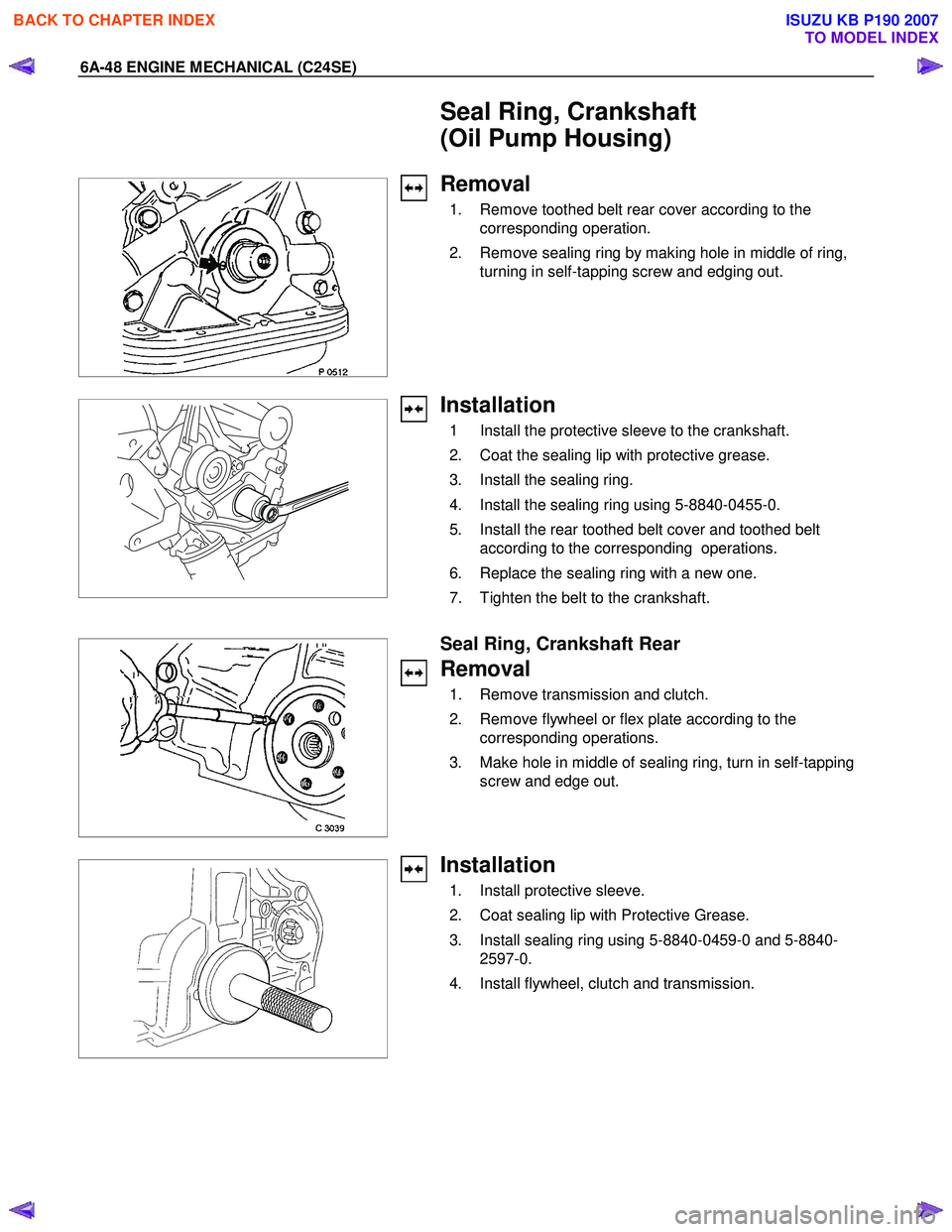
Removal
1. Remove toothed belt rear cover according to the
corresponding operation.
2. Remove sealing ring by making hole in middle of ring, turning in self-tapping screw and edging out.
Installation
1 Install the protective sleeve to the crankshaft.
2. Coat the sealing lip with protective grease.
3. Install the sealing ring.
4. Install the sealing ring using 5-8840-0455-0.
5. Install the rear toothed belt cover and toothed belt according to the corresponding operations.
6. Replace the sealing ring with a new one.
7. Tighten the belt to the crankshaft.
Seal Ring, Crankshaft Rear
Removal
1. Remove transmission and clutch.
2. Remove flywheel or flex plate according to the corresponding operations.
3. Make hole in middle of sealing ring, turn in self-tapping screw and edge out.
Installation
1. Install protective sleeve.
2. Coat sealing lip with Protective Grease.
3. Install sealing ring using 5-8840-0459-0 and 5-8840- 2597-0.
4. Install flywheel, clutch and transmission.
BACK TO CHAPTER INDEX
TO MODEL INDEX
ISUZU KB P190 2007