Page 985 of 6020
FUEL SYSTEM 6C – 21
RTW 46CSH000201
Installation
1. Injection Pump
1) Install the injection pump gear (W hen gear is removed).
Injection Pump Gear Nut N⋅m (kg ⋅m/lb ft)
64 (6.5 / 47)
2) Bring the piston in the No.1 cylinder to TDC on the
compression stroke by turning the crankshaft until the
crankshaft pulley TDC line aligned with the timing
mark.
020L200017
3) Install the injection pump to the timing gear case with
align the timing mark on the pump gear to the arrow
mark on the timing gear case cover.
4) Check that the setting marks of the injection pump gear and the idler gear B are aligned.
5) Remove the lock bolt (M6 × 30) from the idle gear “B”.
6C-7
6) Tighten the injection pump fixing bolts to the specified
torque.
Injection Pump Bolts Torque N·m (kg·m/lb ft)
19 (1.9 / 14)
BACK TO CHAPTER INDEX
TO MODEL INDEX
ISUZU KB P190 2007
Page 986 of 6020

6C – 22 FUEL SYSTEM
4JA1T (L)
RTW 46CSH000101
4JA1TC/4JH1TC
RTW 36AMH000101
2. Injection Pump Bracket
1) Install the injection pump bracket (6) and the bracket bolts (7) and (8) to the cylinder body. Temporarily
tighten the bracket bolts.
2) Tighten the bracket bolts (7) to the specified torque.
3) Tighten the bracket bolts (8) to the specified torque.
Note:
Tighten the bracket bolt (8) first.
Injection Pump Bracket Torque N·m(kg·m / lb ft)
(8) 19 (1.9 / 14)
(7) 40 (4.1 / 30)
3. Timing Check Hole Cover
Install the timing check hole cover and tighten bolts to the
specified torque.
Timing Check Hole Cover Bolts
Torque N·m(kg·m / lb ft)
8 (0.8 / 69)
4. Injection Pump Cover (4JA1TC/4JH1TC only)
5. Intake Manifold
1) Install the intake manifold with gasket.
Intake Manifold Bolts
Torque N·m(kg·m / lb ft)
19 (1.9 / 14)
Intake Manifold Nuts Torque N·m(kg·m / lb ft)
24 (2.4 / 17)
2) Install the EGR valve to the intake manifold and EGR pipe temporarily.
3) Tighten the nuts and bolts to the specified torque
Torque N ⋅m (kg ⋅m/lb ft)
Nuts 24 (2.4/17)
Bolts 27 (2.8/20)
BACK TO CHAPTER INDEX
TO MODEL INDEX
ISUZU KB P190 2007
Page 987 of 6020

FUEL SYSTEM 6C – 23
6. Injection Pipe
Install the injection pipe.
Injection Pipe Torque N·m(kg·m / lb ft)
29 (3.0 / 22)
Nozzle Side (4JA1TC/4JH1TC) N·m(kg·m / lb ft)
29 (3.0 / 22)
Pump Side (4JA1TC/4JH1TC) N·m(kg·m / lb ft)
40 (4.1 / 30)
7. Injection Pipe Clip Install the injection pipe clip.
Note:
Make absolutely sure that the clip is correctly
positioned.
Injection Pipe Clip Torque N·m(kg·m / lb in)
8 (0.8 / 69)
8. Leak Off Pipe and Leak Off Hose
Install the leak off pipe to injection nozzle and connect the
leak off hose to the injection pump.
9. Fuel Filter Bracket (Except EURO III model)
Install the fuel filter bracket and tighten bolts to the
specified torque.
Fuel Filter Bracket Bolts Torque N·m(kg·m / lb ft)
21 (2.1 / 15)
10. Fuel Filter Assembly (Except EURO III model) Install the fuel filter assembly to bracket and tighten bolts
to the specified torque.
Fuel Filter Assembly Bolts
Torque N·m(kg·m / lb ft)
21 (2.1 / 15)
11. Fuel Pipe
1) Connect the fuel hoses to the fuel filter or priming pump.
2) Connect the fuel hoses to the injection pump.
12. Oil Level Gauge Install the oil level gauge and tighten bolts to the specified
torque.
Oil Level Gauge Bolts
Torque N·m(kg·m / lb ft)
M8: 19 (1.9 / 14)
M6: 8 (0.8/6 lb in)
BACK TO CHAPTER INDEX
TO MODEL INDEX
ISUZU KB P190 2007
Page 988 of 6020
6C – 24 FUEL SYSTEM
13. Throttle Position Sensor Harness Connector
(4JA1TC/4JH1TC only)
Reconnect the harness connector to the throttle position
sensor.
14. Power Steering Pump Bracket
15. Fan
16. Vacuum Hose
Connect the vacuum hose to the EGR valve and the
intake throttle.
Euro under Euro I Euro II Euro III
4JA1L without with with Not used
4JA1TC Not used Not used Not used With cooler
(EGR cooler)
4JH1TC without with with With
(EGR cooler)
17. Accelerator Control Cable
1) Connect the accelerator cable to the injection pump (4JA1T) the intake throttle. (4JA1TC/4JH1TC only)
18. Power Steering Pump Assembly
19. Drive Belt
Install the drive belt and adjust the belt tension.
20. Battery
BACK TO CHAPTER INDEX
TO MODEL INDEX
ISUZU KB P190 2007
Page 1001 of 6020
FUEL SYSTEM 6C – 37
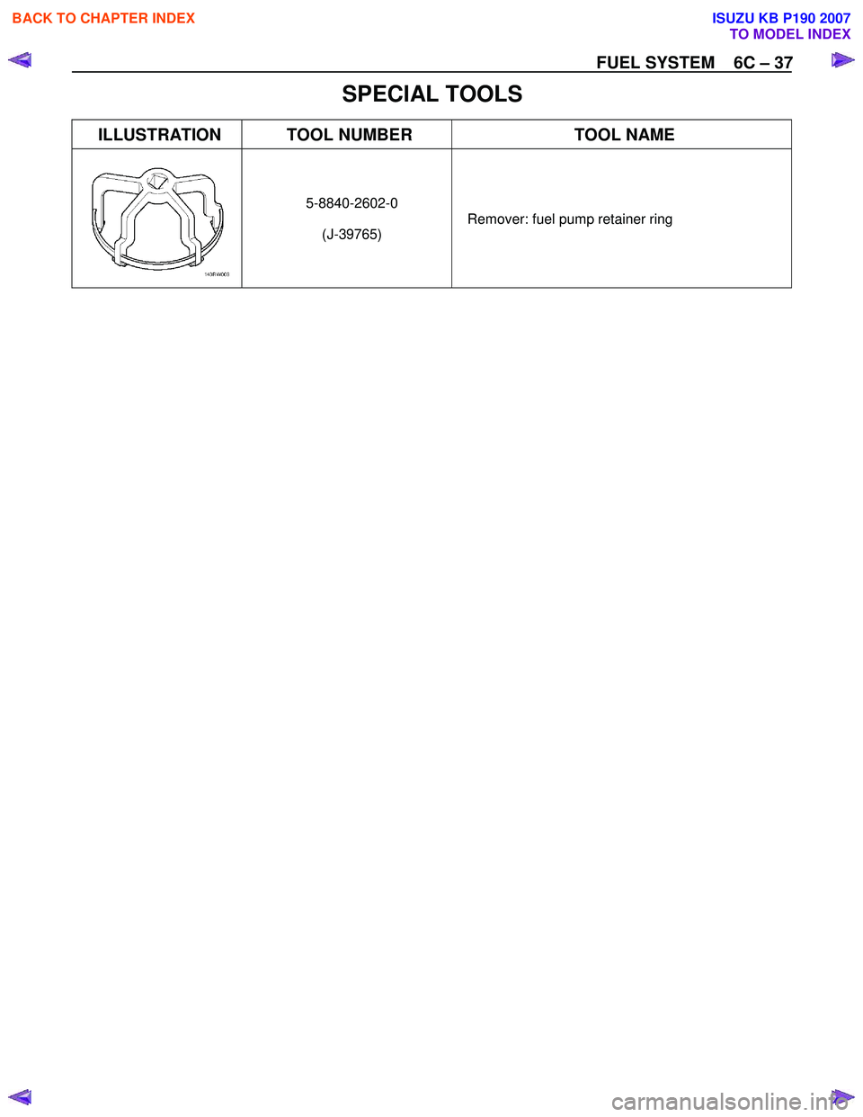
SPECIAL TOOLS
ILLUSTRATION TOOL NUMBER TOOL NAME
5-8840-2602-0
(J-39765) Remover: fuel pump retainer ring
BACK TO CHAPTER INDEX
TO MODEL INDEX
ISUZU KB P190 2007
Page 1053 of 6020
Engine Control System (4JH1) 6E-19
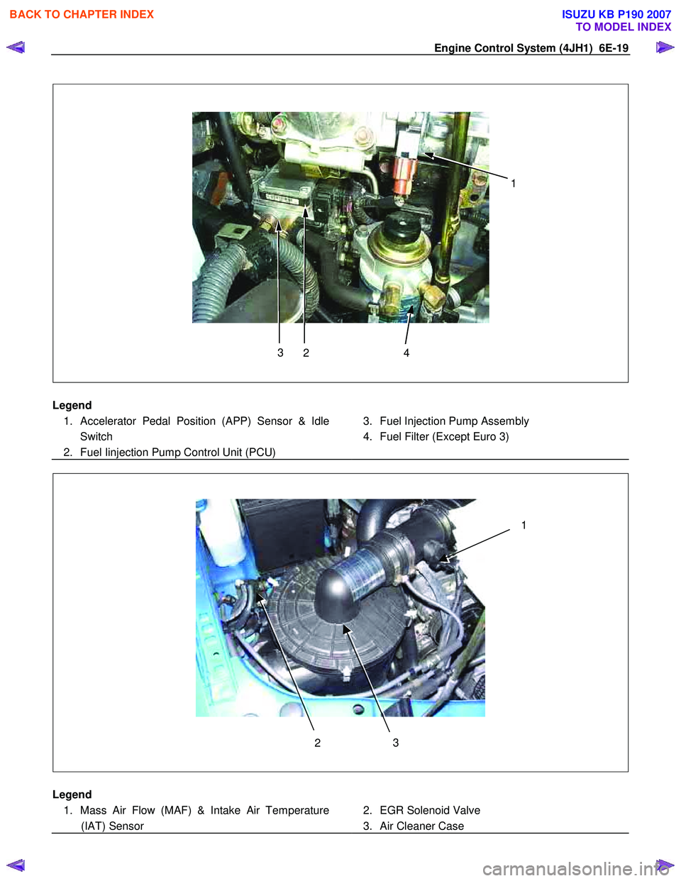
4
2
3 1
Legend
1. Accelerator Pedal Position (APP) Sensor & Idle Switch
2. Fuel Iinjection Pump Control Unit (PCU)
3. Fuel Injection Pump Assembly
4. Fuel Filter (Except Euro 3)
3
2 1
Legend
1. Mass Air Flow (MAF) & Intake Air Temperature (IAT) Sensor
2. EGR Solenoid Valve
3. Air Cleaner Case
BACK TO CHAPTER INDEX
TO MODEL INDEX
ISUZU KB P190 2007
Page 1061 of 6020
Engine Control System (4JH1) 6E-27
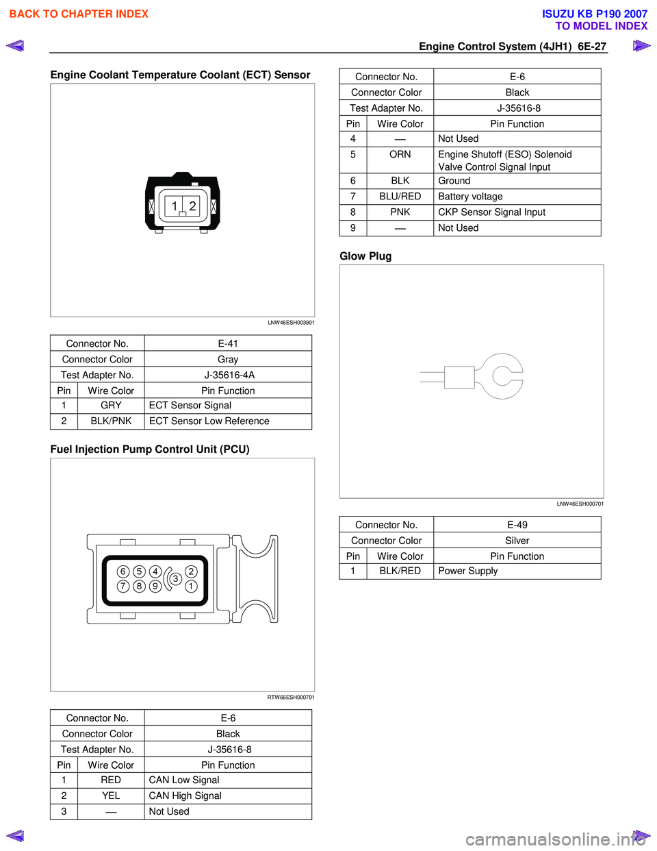
Engine Coolant Temperature Coolant (ECT) Sensor
LNW 46ESH003901
Connector No. E-41
Connector Color Gray
Test Adapter No. J-35616-4A
Pin W ire Color Pin Function
1 GRY ECT Sensor Signal
2 BLK/PNK ECT Sensor Low Reference
Fuel Injection Pump Control Unit (PCU)
RTW 66ESH000701
Connector No. E-6
Connector Color Black
Test Adapter No. J-35616-8
Pin W ire Color Pin Function
1 RED CAN Low Signal
2 YEL CAN High Signal
3
Not Used
Connector No. E-6
Connector Color Black
Test Adapter No. J-35616-8
Pin W ire Color Pin Function
4
Not Used
5 ORN Engine Shutoff (ESO) Solenoid
Valve Control Signal Input
6 BLK Ground
7 BLU/RED Battery voltage
8 PNK CKP Sensor Signal Input
9
Not Used
Glow Plug
LNW 46ESH000701
Connector No. E-49
Connector Color Silver
Pin W ire Color Pin Function
1 BLK/RED Power Supply
BACK TO CHAPTER INDEX
TO MODEL INDEX
ISUZU KB P190 2007
Page 1067 of 6020
Engine Control System (4JH1) 6E-33
Diagnostic System Check - Engine
Controls
Description
The Diagnostic System Check-Engine Controls is an
organized approach to identifying a condition that is
created by a malfunction in the electronic engine control
system. The Diagnostic System Check must be the
starting point for any driveability concern. The
Diagnostic System Check directs the service technician
to the next logical step in order to diagnose the concern.
Understanding and correctly using the diagnostic table
reduces diagnostic time, and prevents the replacement
of good parts.
Test Description
The numbers below refer to the step numbers on the
diagnostic table.
2. Lack of communication may be because of a partial
or a total malfunction of the Keyword 2000 serial data
circuit. The specified procedure determines the
particular condition.
11. If there are other modules with DTCs set, refer to
the DTC list. The DTC list directs you to the appropriate
diagnostic procedure. If the control module stores
multiple DTCs, diagnose the DTCs in the following
order.
• Component level DTCs, such as sensor DTCs,
solenoid DTCs, actuator DTCs, and relay DTCs.
Diagnose the multiple DTCs within this category in
numerical order. Begin with the lowest numbered
DTC, unless the diagnostic table directs you
otherwise.
Important:
• DO NOT perform this diagnostic if there is not a
driveability concern, unless another procedure
directs you to this diagnostic.
• Before you proceed with diagnosis, search fo
r
applicable service bulletins.
• Unless a diagnostic procedure instructs you, DO
NOT clear the DTCs.
• If there is a condition with the starting system, refe
r
to the starting system section in the engine
mechanical.
• Ensure the battery has a full charge.
• Ensure the battery cables (+) (-) are clean and
tight.
• Ensure the ECM grounds are clean, tight, and in
the correct location.
• Ensure the ECM harness connectors are clean and
correctly connected.
• Ensure the ECM terminals are clean and correctl
y
mating.
• Ensure the fuel injection pump control unit (PCU)
ground is clean, tight, and in the correct location.
• Ensure the PCU harness connectors are clean and
correctly connected.
• Ensure the PCU terminals are clean and correctl
y
mating.
• Ensure the vehicle maintenance has been done
enough.
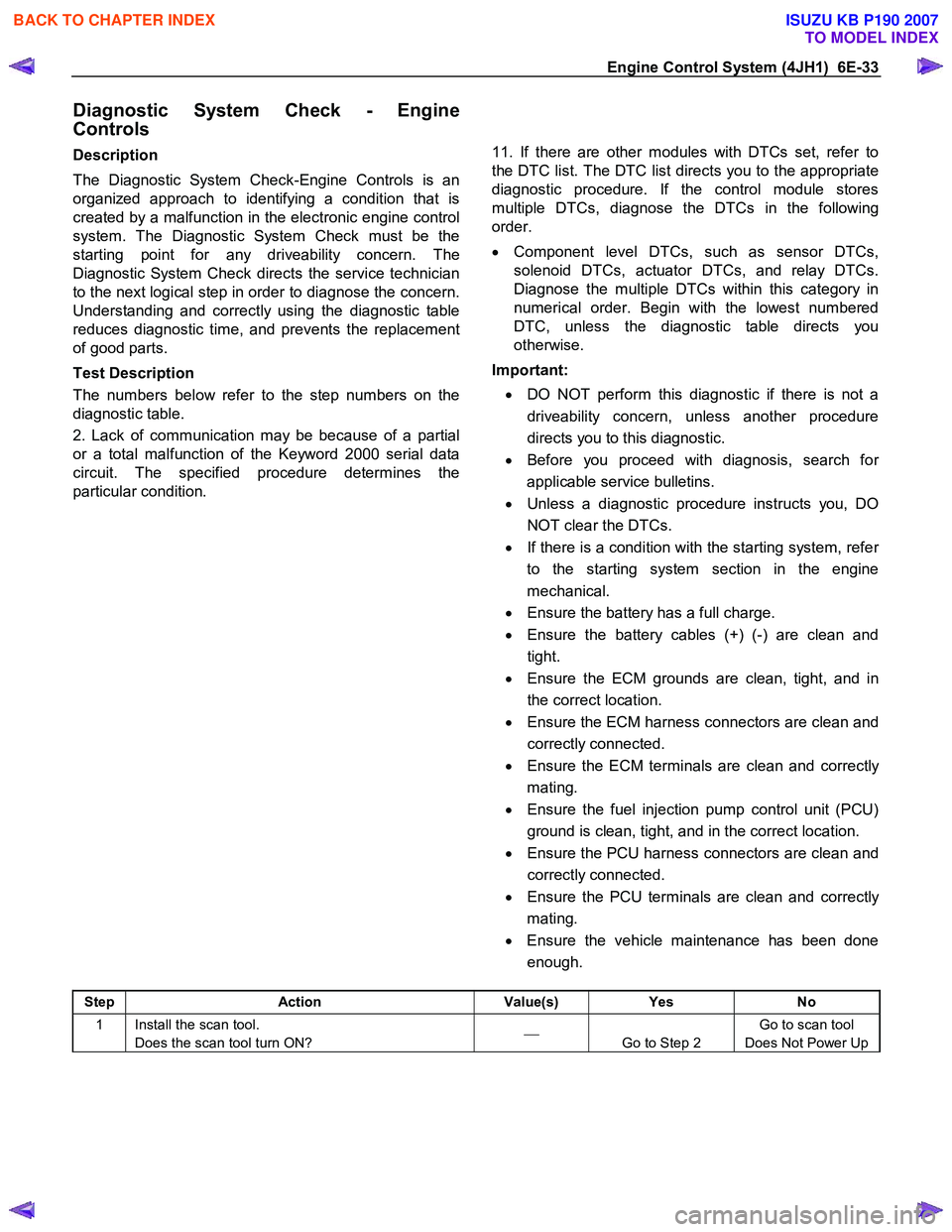
Step Action Value(s) Yes No
1 Install the scan tool.
Does the scan tool turn ON?
Go to Step 2 Go to scan tool
Does Not Power Up
BACK TO CHAPTER INDEX
TO MODEL INDEX
ISUZU KB P190 2007