Page 3284 of 6020

Engine Management – V6 – Diagnostics Page 6C1-2–6
• Use Tech 2 to clear DTC/s.
Type C – Non-Emission Related DTCs
The ECM takes the following action when a Type A DTC runs and fails:
• sets a current Type C DTC that represents the fault condition, and
• records the operating conditions at the time the DTC is logged and stores this information in the Failure Record,
and:
NOTE
The instrument cluster malfunction indicator lamp
(MIL) is not activated when a Type C DTC sets.
Conditions for Clearing Type C DTCs
• The current DTC clears when there is no fault condition in the current ECM self-diagnostics.
• Type C History DTC clears when there is no fault condition after 40 consecutive warm-up cycles.
• Use Tech 2 to clear DTCs.
Current DTCs
A DTC is a Current DTC if the fault condition that triggers that DTC is present during the last ECM self-diagnostics.
History DTCs
A DTC is a History DTC if the fault condition that triggers that DTC is not present during the last ECM self-diagnostics.
1.5 Warning Caution and Notes
This Section contains various W ARNINGS, CAUTIONS and NOTE statements that you must observe carefully to reduce
the risk of death or injury during service, repair procedures or vehicle operation. Incorrect service or repair procedures
may damage the vehicle or cause operational faults. W ARNINGS, CAUTION and NOTE statements are not exhaustive.
GM Holden LTD can not possibly warn of all the potentially hazardous consequences of failure to follow these
instructions.
Definition of WARNING, CAUTION and NOTE Statements
Diagnosis and repair procedures in this Section contain both general and specific W ARNING, CAUTION and NOTE
statements. GM Holden LTD is dedicated to the presentation of service information that helps the technician to diagnose
and repair the systems necessary for proper operation of the vehicle. Certain procedures may present a hazard to the
technician if they are not followed in the recommended manner. W ARNING, CAUTION and NOTE statements are
designed to help prevent these hazards from occurring, but not all hazards can be foreseen.
WARNING defined
A W ARNING statement immediately precedes an operating procedure or maintenance practice which, if not correctly
followed, could result in death or injury. A W ARNING statement alerts you to take necessary action or not to take a
prohibited action. If a W ARNING statement is ignored, the following consequences may occur:
• Death or injury to the technician or other personnel working on the vehicle,
• Death or injury to other people in or near the workplace area, and / or
• Death or injury to the driver / or passenger(s) of the vehicle or other people, if the vehicle has been improperly
repaired.
CAUTION defined
A CAUTION statement immediately precedes an operating procedure or maintenance practice which, if not correctly
followed, could result in damage to or destruction of equipment, or corruption of data. If a CAUTION statement is
ignored, the following consequences may occur:
BACK TO CHAPTER INDEX
TO MODEL INDEX
ISUZU KB P190 2007
Page 3285 of 6020

Engine Management – V6 – Diagnostics Page 6C1-2–7
• Damage to the vehicle,
• Unnecessary vehicle repairs or component replacement,
• Faulty operation or performance of any system or component being repaired,
• Damage to any system or components which depend on the proper operation of the system or component being
repaired,
• Faulty operation or performance of any systems or components which depend on the proper operation or
performance of the system or component under repair,
• Damage to fasteners, basic tools or special tools and / or
• Leakage of coolant, lubricant or other vital fluids.
NOTE defined
A NOTE statement immediately precedes or follows an operating procedure, maintenance practice or condition that
requires highlighting. A NOTE statement also emphasises necessary characteristics of a diagnostic or repair procedure.
A NOTE statement is designed to:
• Clarify a procedure,
• Present additional information for accomplishing a procedure,
• Give insight into the reasons for performing a procedure in the recommended manner, and / or
• Present information that gives the technician the benefit of past experience in accomplishing a procedure with
greater ease.
BACK TO CHAPTER INDEX
TO MODEL INDEX
ISUZU KB P190 2007
Page 3286 of 6020
Engine Management – V6 – Diagnostics Page 6C1-2–8
2 GM LAN Serial Communication
Circuit
Figure 6C1-2 – 1
BACK TO CHAPTER INDEX
TO MODEL INDEX
ISUZU KB P190 2007
Page 3287 of 6020
Engine Management – V6 – Diagnostics Page 6C1-2–9
3 Wiring Diagrams and Connector
Charts
3.1 Wiring Diagrams
Figure 6C1-2 – 2
BACK TO CHAPTER INDEX
TO MODEL INDEX
ISUZU KB P190 2007
Page 3288 of 6020
Engine Management – V6 – Diagnostics Page 6C1-2–10
Figure 6C1-2 – 3
BACK TO CHAPTER INDEX
TO MODEL INDEX
ISUZU KB P190 2007
Page 3289 of 6020
Engine Management – V6 – Diagnostics Page 6C1-2–11
Figure 6C1-2 – 4
BACK TO CHAPTER INDEX
TO MODEL INDEX
ISUZU KB P190 2007
Page 3290 of 6020

Engine Management – V6 – Diagnostics Page 6C1-2–12
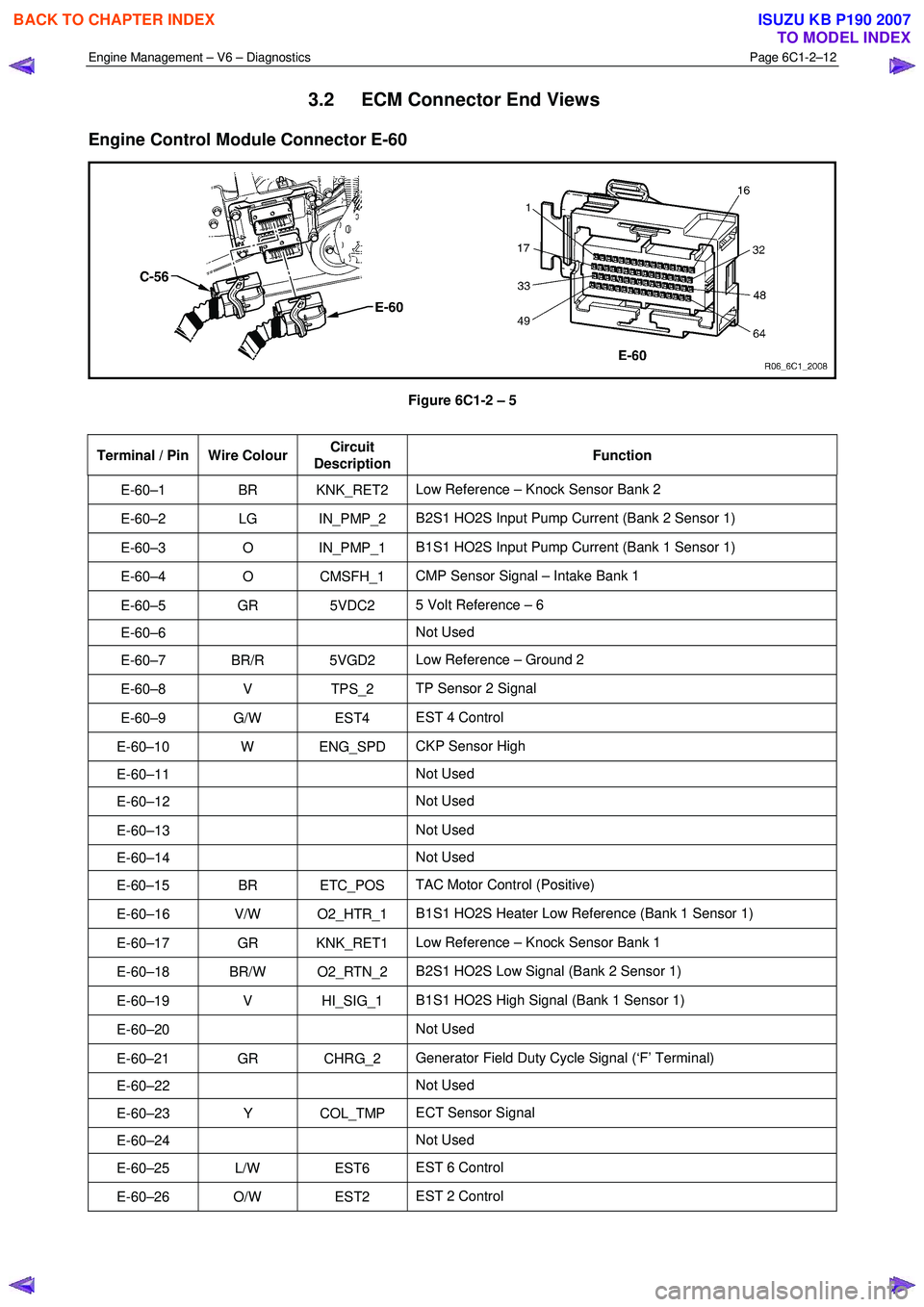
3.2 ECM Connector End Views
Engine Control Module Connector E-60
Figure 6C1-2 – 5
Terminal / Pin Wire Colour Circuit
Description Function
E-60–1 BR KNK_RET2
Low Reference – Knock Sensor Bank 2
E-60–2 LG IN_PMP_2 B2S1 HO2S Input Pump Current (Bank 2 Sensor 1)
E-60–3 O IN_PMP_1 B1S1 HO2S Input Pump Current (Bank 1 Sensor 1)
E-60–4 O CMSFH_1 CMP Sensor Signal – Intake Bank 1
E-60–5 GR 5VDC2 5 Volt Reference – 6
E-60–6 Not Used
E-60–7 BR/R 5VGD2 Low Reference – Ground 2
E-60–8 V TPS_2 TP Sensor 2 Signal
E-60–9 G/W EST4 EST 4 Control
E-60–10 W ENG_SPD CKP Sensor High
E-60–11 Not Used
E-60–12 Not Used
E-60–13 Not Used
E-60–14 Not Used
E-60–15 BR ETC_POS TAC Motor Control (Positive)
E-60–16 V/W O2_HTR_1 B1S1 HO2S Heater Low Reference (Bank 1 Sensor 1)
E-60–17 GR KNK_RET1 Low Reference – Knock Sensor Bank 1
E-60–18 BR/W O2_RTN_2 B2S1 HO2S Low Signal (Bank 2 Sensor 1)
E-60–19 V HI_SIG_1 B1S1 HO2S High Signal (Bank 1 Sensor 1)
E-60–20 Not Used
E-60–21 GR CHRG_2 Generator Field Duty Cycle Signal (‘F’ Terminal)
E-60–22 Not Used
E-60–23 Y COL_TMP ECT Sensor Signal
E-60–24 Not Used
E-60–25 L/W EST6 EST 6 Control
E-60–26 O/W EST2 EST 2 Control
BACK TO CHAPTER INDEX
TO MODEL INDEX
ISUZU KB P190 2007
Page 3291 of 6020

Engine Management – V6 – Diagnostics Page 6C1-2–13
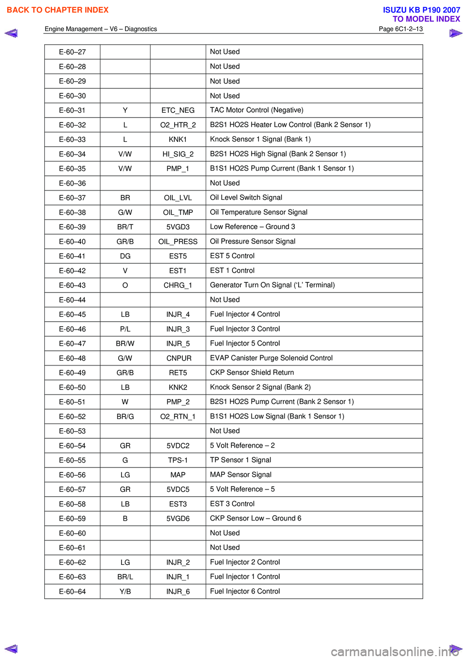
E-60–27 Not Used
E-60–28 Not Used
E-60–29 Not
Used
E-60–30 Not Used
E-60–31 Y ETC_NEG TAC Motor Control (Negative)
E-60–32 L O2_HTR_2 B2S1 HO2S Heater Low Control (Bank 2 Sensor 1)
E-60–33 L KNK1 Knock Sensor 1 Signal (Bank 1)
E-60–34 V/W HI_SIG_2 B2S1 HO2S High Signal (Bank 2 Sensor 1)
E-60–35 V/W PMP_1 B1S1 HO2S Pump Current (Bank 1 Sensor 1)
E-60–36 Not Used
E-60–37 BR OIL_LVL Oil Level Switch Signal
E-60–38 G/W OIL_TMP Oil Temperature Sensor Signal
E-60–39 BR/T 5VGD3 Low Reference – Ground 3
E-60–40 GR/B OIL_PRESS Oil Pressure Sensor Signal
E-60–41 DG EST5 EST 5 Control
E-60–42 V EST1 EST 1 Control
E-60–43 O CHRG_1 Generator Turn On Signal (‘L’ Terminal)
E-60–44 Not Used
E-60–45 LB INJR_4 Fuel Injector 4 Control
E-60–46 P/L INJR_3 Fuel Injector 3 Control
E-60–47 BR/W INJR_5 Fuel Injector 5 Control
E-60–48 G/W CNPUR EVAP Canister Purge Solenoid Control
E-60–49 GR/B RET5 CKP Sensor Shield Return
E-60–50 LB KNK2 Knock Sensor 2 Signal (Bank 2)
E-60–51 W PMP_2 B2S1 HO2S Pump Current (Bank 2 Sensor 1)
E-60–52 BR/G O2_RTN_1 B1S1 HO2S Low Signal (Bank 1 Sensor 1)
E-60–53 Not Used
E-60–54 GR 5VDC2 5 Volt Reference – 2
E-60–55 G TPS-1 TP Sensor 1 Signal
E-60–56 LG MAP MAP Sensor Signal
E-60–57 GR 5VDC5 5 Volt Reference – 5
E-60–58 LB EST3 EST 3 Control
E-60–59 B 5VGD6 CKP Sensor Low – Ground 6
E-60–60 Not Used
E-60–61 Not Used
E-60–62 LG INJR_2 Fuel Injector 2 Control
E-60–63 BR/L INJR_1 Fuel Injector 1 Control
E-60–64 Y/B INJR_6 Fuel Injector 6 Control
BACK TO CHAPTER INDEX
TO MODEL INDEX
ISUZU KB P190 2007