Page 1594 of 6020
6D-6 ENGINE ELECTRICAL (4JK1/4JJ1)
No charging
Possible problem Countermeasure
Dead battery Replace
Open or shorted wiring
Open or shorted ammeter
Loose wiring connections Repair
One or more generator coils open or shorted
Bad diode
Bad regulator Replace
Loose regulator connections
Repair
Inadequate charging
Possible problem Countermeasure
Dead battery Replace
Open or shorted wiring
Loose wiring connections Repair
Loose generator drive belt
Adjust belt tension
Stator coil intermittent short
Bad diode Replace
Loose battery connections
Repair
Bad regulator Replace
Loose regulator connections Repair
Excessive charging
Possible problem Countermeasure
Bad regulator Replace
Unstable charging current
Possible problem Countermeasure
Open wiring connection or broken wire Repair
Loose generator drive belt Adjust belt tension
Open or shorted stator coil Replace
Loose terminal connections Repair
Bad regulator Replace
Loose regulator terminal connections Repair
Abnormal operating noise
Possible problem Countermeasure
Loose generator drive belt Adjust belt tension
Bad bearing Replace
Loose rotor core or stator core Repair
Bad diode Replace
Open or shorted stator coil Replace
BACK TO CHAPTER INDEX
TO MODEL INDEX
ISUZU KB P190 2007
Page 1600 of 6020
6D-12 ENGINE ELECTRICAL (4JK1/4JJ1)
4. Check for conductivity between the slip rings and
the rotor core. If there is continuity, the roto
r
assembly must be replaced.
066RS017
Stator Coil
1. Measure the stator coil resistance. If the
resistance is less than the specified value, the
stator coil must be replaced.
Stator coil resistance
0.07Ω at 20 °C (68 °F)
066RS034
2. Measure the resistance between the stator coil
and the stator core. If the resistance is less than
the specified value, the stator coil must be
replaced.
Stator coil/core resistance MΩ
1
066RS035
Brushes
Measure the brush height. If the height is less than the
specified limit, the brushes must be replaced.
Brush height mm (in)
Standard 18 (0.709)
Limit 5.5 (0.217)
066RW 024
BACK TO CHAPTER INDEX
TO MODEL INDEX
ISUZU KB P190 2007
Page 1602 of 6020
6D-14 ENGINE ELECTRICAL (4JK1/4JJ1)
Reassembly
Follow the disassembly steps in reverse order to
reassemble the generator. Pay close attention to the
items below.
• Be very careful not to reverse battery polarity.
Reversed battery polarity will destroy the rectifie
r
diodes.
• Do not ground the generator B-terminal. Heat and
fire damage to the harness will result.
• If using a fast charge procedure, be sure to
disconnect the battery positive cable. If you do not,
the rectifier diodes will be exposed to high positive
voltage that will destroy them.
• Be very careful to reassemble the parts to thei
r
original positions. Particular care must be taken
with insulated parts.
• Carefully clean all insulated parts so that they are
completely free of oil and/or grease.
• Be sure that B-terminal twist-type stoppers (round
terminal) are securely inserted before tightening
the nuts.
Final Assembly
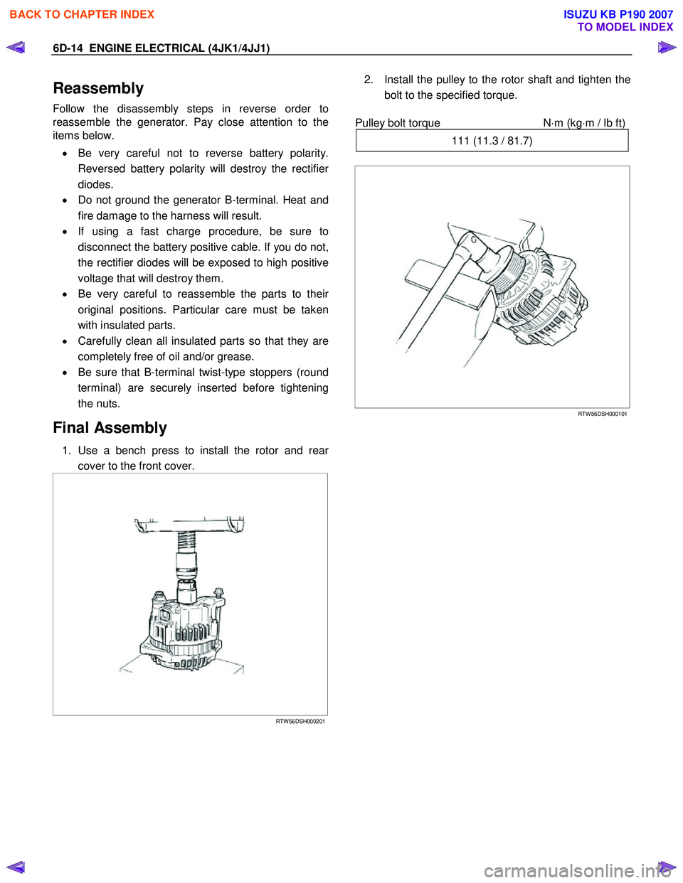
1. Use a bench press to install the rotor and rear
cover to the front cover.
RTW 56DSH000201
2. Install the pulley to the rotor shaft and tighten the
bolt to the specified torque.
Pulley bolt torque N
⋅m (kg⋅m / lb ft)
111 (11.3 / 81.7)
RTW 56DSH000101
BACK TO CHAPTER INDEX
TO MODEL INDEX
ISUZU KB P190 2007
Page 1603 of 6020
ENGINE ELECTRICAL (4JK1/4JJ1) 6D-15
Starter Motor
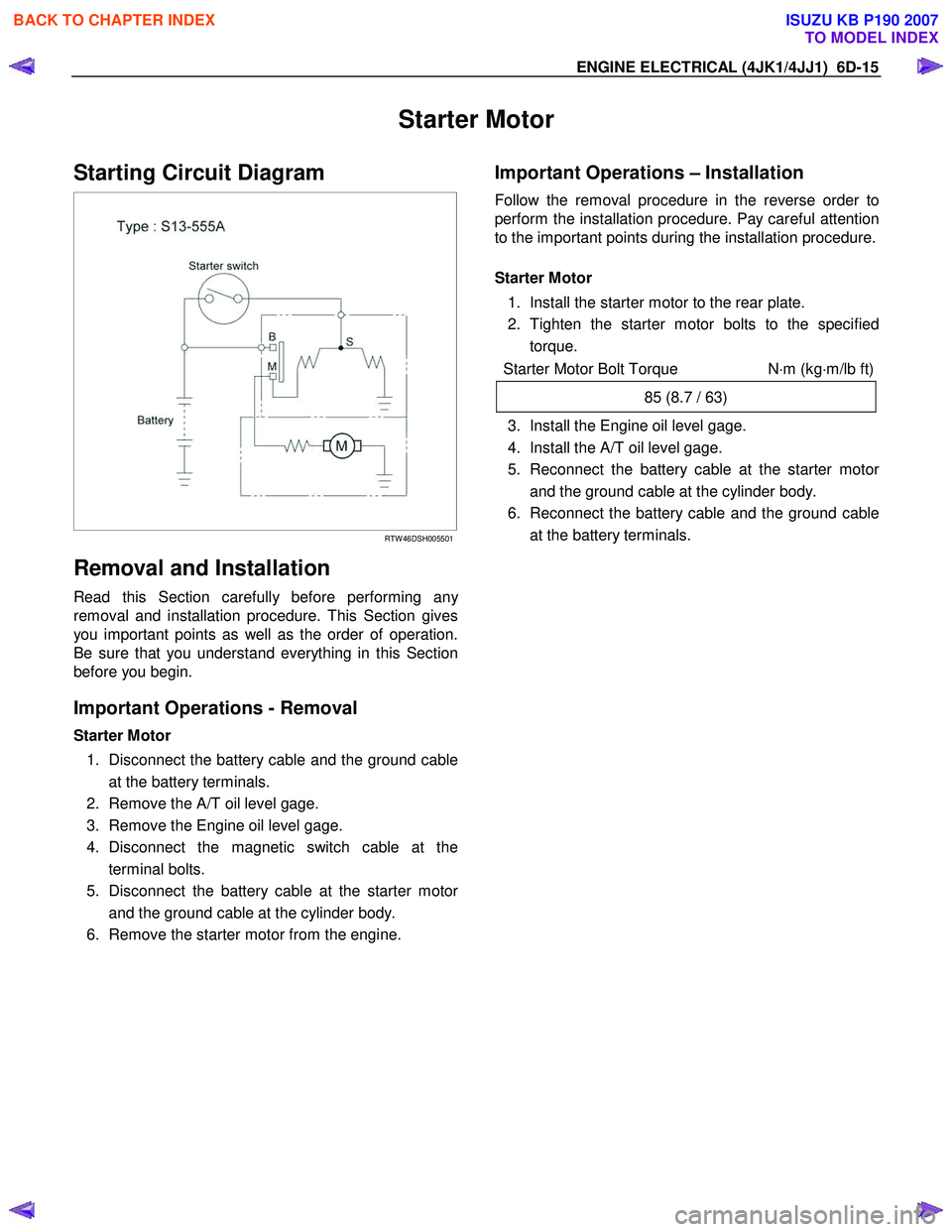
Starting Circuit Diagram
RTW 46DSH005501
Removal and Installation
Read this Section carefully before performing any
removal and installation procedure. This Section gives
you important points as well as the order of operation.
Be sure that you understand everything in this Section
before you begin.
Important Operations - Removal
Starter Motor
1. Disconnect the battery cable and the ground cable at the battery terminals.
2. Remove the A/T oil level gage.
3. Remove the Engine oil level gage.
4. Disconnect the magnetic switch cable at the terminal bolts.
5. Disconnect the battery cable at the starter moto
r
and the ground cable at the cylinder body.
6. Remove the starter motor from the engine.
Important Operations – Installation
Follow the removal procedure in the reverse order to
perform the installation procedure. Pay careful attention
to the important points during the installation procedure.
Starter Motor
1. Install the starter motor to the rear plate.
2. Tighten the starter motor bolts to the specified torque.
Starter Motor Bolt Torque N⋅m (kg ⋅m/lb ft)
85 (8.7 / 63)
3. Install the Engine oil level gage.
4. Install the A/T oil level gage.
5. Reconnect the battery cable at the starter moto
r
and the ground cable at the cylinder body.
6. Reconnect the battery cable and the ground cable at the battery terminals.
BACK TO CHAPTER INDEX
TO MODEL INDEX
ISUZU KB P190 2007
Page 1609 of 6020
ENGINE ELECTRICAL (4JK1/4JJ1) 6D-21
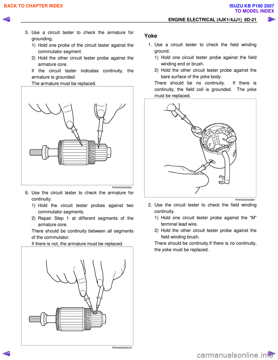
5. Use a circuit tester to check the armature for
grounding.
1) Hold one probe of the circuit tester against the commutator segment.
2) Hold the other circuit tester probe against the armature core.
If the circuit tester indicates continuity, the armature is grounded.
The armature must be replaced.
RTW 46DSH003601
6. Use the circuit tester to check the armature for
continuity.
1) Hold the circuit tester probes against two commutator segments.
2) Repair Step 1 at different segments of the armature core.
There should be continuity between all segments of the commutator.
If there is not, the armature must be replaced.
RTW 46DSH003701
Yoke
1. Use a circuit tester to check the field winding
ground.
1) Hold one circuit tester probe against the field winding end or brush.
2) Hold the other circuit tester probe against the bare surface of the yoke body.
There should be no continuity. If there is continuity, the field coil is grounded. The yoke
must be replaced.
RTW 46DSH003801
2. Use the circuit tester to check the field winding
continuity.
1) Hold one circuit tester probe against the “M” terminal lead wire.
2) Hold the other circuit tester probe against the field winding brush.
There should be continuity.If there is no continuity, the yoke must be replaced.
BACK TO CHAPTER INDEX
TO MODEL INDEX
ISUZU KB P190 2007
Page 1615 of 6020
ENGINE ELECTRICAL (4JK1/4JJ1) 6D-27
Magnetic Switch
The following tests must be performed with the starter
motor fully assembled.
The yoke lead wire must be disconnected from the “M”
terminal.
To prevent coil burning, complete each test as quickl
y
as possible (within three to five seconds).
Temporarily connect the solenoid switch between the
clutch and the housing and run the following test.
Complete each test within three to five seconds.
1. Pull-in Test
Connect the battery negative terminal with the solenoid switch body and the M terminal. W hen
current is applied to the S terminal from the batter
y
positive terminal, the pinion should flutter.
RTW 46DSH004601
2. Hold-in Maintenance Test
Disconnect the lead at the M terminal. The pinion should continue to flutter.
RTW 46DSH005901
3. Return Test
Disconnect the battery positive lead at the S terminal.
The pinion should return to its home position.
RTW 46DSH004701
BACK TO CHAPTER INDEX
TO MODEL INDEX
ISUZU KB P190 2007
Page 1682 of 6020

ENGINE CONTROL SYSTEM (4JK1/4JJ1) 6E-65
Circuit/ System Testing Engine Cranks but Does Not Run (2 of 2)
StepAction Value(s)Yes No
1 1. Remove the engine cover.
2. Perform the Injector Force Drive with a scan tool.
3. Command each injector ON and verify clicking noise (solenoid operating noise).
Is there an injector that does not create a clicking
noise (solenoid operating noise), contains an
interrupted noise or abnormal noise when
commanded ON? —
Go to Step 8 Go to Step 2
2 1. Inspect the high pressure side between the
fuel supply pump and the fuel injectors for fuel
leakage. The following components may
contain an external leak.
• Fuel supply pump
• Fuel rail
•Pressure limiter valve
• Fuel rail pressure (FRP) sensor
• Fuel pipe between the fuel supply pump and fuel rail
• Fuel pipe between the fuel rail and fuel injectors
• Each fuel pipe sleeve nuts
Notice: Fuel may leak under the cylinder head
cover from the inlet high pressure line. In such
case, the engine oil level will rise. Inspect for fuel
leakage into the engine oil.
2. Repair any fuel system leaks as necessary.
Did you find and correct the condition? —
Go to Step 12 Go to Step 3
3 1. Check the fuel system line connections
between the fuel tank and the fuel supply
pump for tightness and all fuel hoses for cuts,
cracks and for the use of proper clamps.
2. Repair or replace as necessary.
Did you find and correct the condition? —
Go to Step 12 Go to Step 4
BACK TO CHAPTER INDEX
TO MODEL INDEX
ISUZU KB P190 2007
Page 1692 of 6020
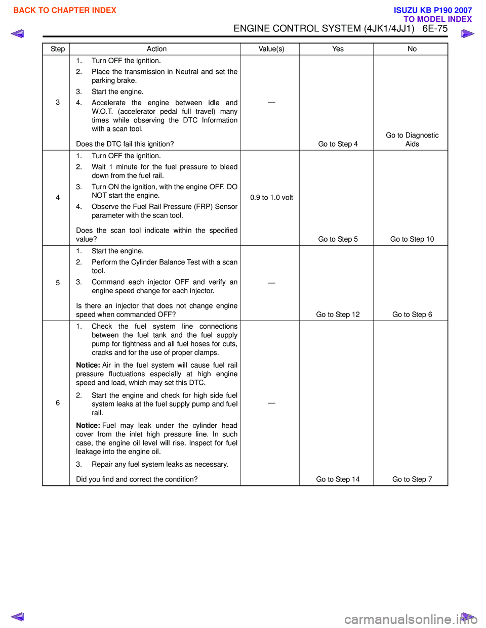
ENGINE CONTROL SYSTEM (4JK1/4JJ1) 6E-75
31. Turn OFF the ignition.
2. Place the transmission in Neutral and set the parking brake.
3. Start the engine.
4. Accelerate the engine between idle and W.O.T. (accelerator pedal full travel) many
times while observing the DTC Information
with a scan tool.
Does the DTC fail this ignition? —
Go to Step 4 Go to Diagnostic
Aids
4 1. Turn OFF the ignition.
2. Wait 1 minute for the fuel pressure to bleed down from the fuel rail.
3. Turn ON the ignition, with the engine OFF. DO NOT start the engine.
4. Observe the Fuel Rail Pressure (FRP) Sensor parameter with the scan tool.
Does the scan tool indicate within the specified
value? 0.9 to 1.0 volt
Go to Step 5 Go to Step 10
5 1. Start the engine.
2. Perform the Cylinder Balance Test with a scan tool.
3. Command each injector OFF and verify an engine speed change for each injector.
Is there an injector that does not change engine
speed when commanded OFF? —
Go to Step 12 Go to Step 6
6 1. Check the fuel system line connections
between the fuel tank and the fuel supply
pump for tightness and all fuel hoses for cuts,
cracks and for the use of proper clamps.
Notice: Air in the fuel system will cause fuel rail
pressure fluctuations especially at high engine
speed and load, which may set this DTC.
2. Start the engine and check for high side fuel system leaks at the fuel supply pump and fuel
rail.
Notice: Fuel may leak under the cylinder head
cover from the inlet high pressure line. In such
case, the engine oil level will rise. Inspect for fuel
leakage into the engine oil.
3. Repair any fuel system leaks as necessary.
Did you find and correct the condition? —
Go to Step 14 Go to Step 7
Step
Action Value(s)Yes No
BACK TO CHAPTER INDEX
TO MODEL INDEX
ISUZU KB P190 2007