2007 ISUZU KB P190 service reset
[x] Cancel search: service resetPage 3543 of 6020
Engine Management – V6 – Service Operations Page 6C1-3–19
Remove
If replacing the ECM, it must be reset prior to
removal. Failure to perform this procedure
will result in the inability to test the ECM for
warranty purposes, refer to ECM Reset in this
Section.
1 Turn the ignition switch off.
2 Disconnect the battery.
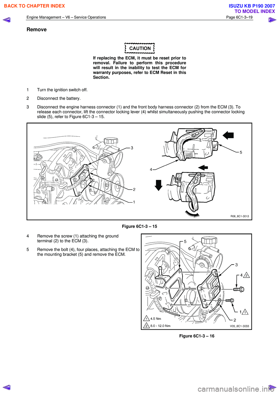
3 Disconnect the engine harness connector (1) and the front body harness connector (2) from the ECM (3). To release each connector, lift the connector locking lever (4) whilst simultaneously pushing the connector locking
slide (5), refer to Figure 6C1-3 – 15.
Figure 6C1-3 – 15
4 Remove the screw (1) attaching the ground terminal (2) to the ECM (3).
5 Remove the bolt (4), four places, attaching the ECM to the mounting bracket (5) and remove the ECM.
Figure 6C1-3 – 16
BACK TO CHAPTER INDEX
TO MODEL INDEX
ISUZU KB P190 2007
Page 3544 of 6020
Engine Management – V6 – Service Operations Page 6C1-3–20
Reinstall
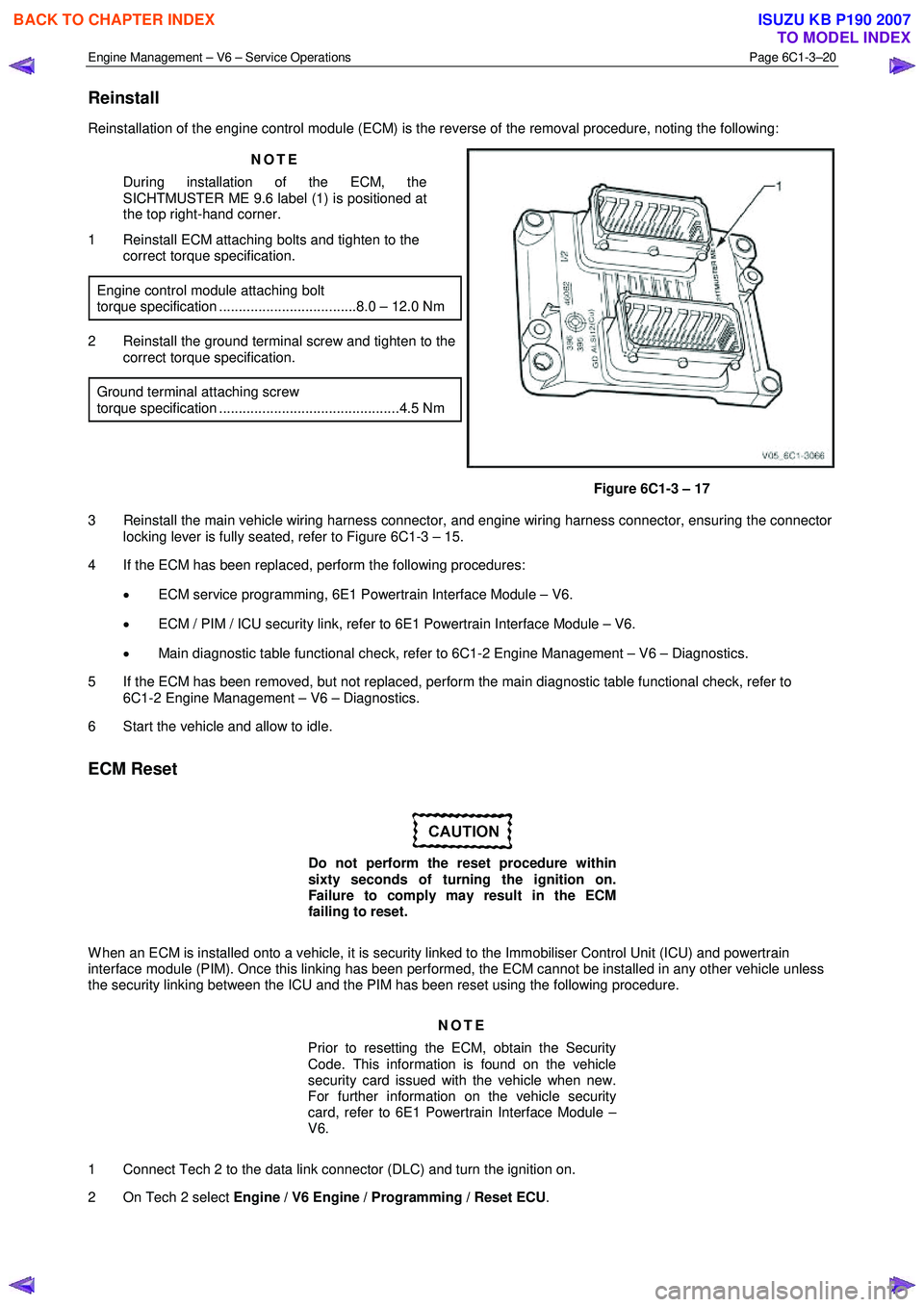
Reinstallation of the engine control module (ECM) is the reverse of the removal procedure, noting the following:
NOTE
During installation of the ECM, the
SICHTMUSTER ME 9.6 label (1) is positioned at
the top right-hand corner.
1 Reinstall ECM attaching bolts and tighten to the correct torque specification.
Engine control module attaching bolt
torque specification ...................................8.0 – 12.0 Nm
2 Reinstall the ground terminal screw and tighten to the correct torque specification.
Ground terminal attaching screw
torque specification ..............................................4.5 Nm
Figure 6C1-3 – 17
3 Reinstall the main vehicle wiring harness connector, and engine wiring harness connector, ensuring the connector locking lever is fully seated, refer to Figure 6C1-3 – 15.
4 If the ECM has been replaced, perform the following procedures:
• ECM service programming, 6E1 Powertrain Interface Module – V6.
• ECM / PIM / ICU security link, refer to 6E1 Powertrain Interface Module – V6.
• Main diagnostic table functional check, refer to 6C1-2 Engine Management – V6 – Diagnostics.
5 If the ECM has been removed, but not replaced, perform the main diagnostic table functional check, refer to 6C1-2 Engine Management – V6 – Diagnostics.
6 Start the vehicle and allow to idle.
ECM Reset
Do not perform the reset procedure within
sixty seconds of turning the ignition on.
Failure to comply may result in the ECM
failing to reset.
W hen an ECM is installed onto a vehicle, it is security linked to the Immobiliser Control Unit (ICU) and powertrain
interface module (PIM). Once this linking has been performed, the ECM cannot be installed in any other vehicle unless
the security linking between the ICU and the PIM has been reset using the following procedure.
NOTE
Prior to resetting the ECM, obtain the Security
Code. This information is found on the vehicle
security card issued with the vehicle when new.
For further information on the vehicle security
card, refer to 6E1 Powertrain Interface Module –
V6.
1 Connect Tech 2 to the data link connector (DLC) and turn the ignition on.
2 On Tech 2 select Engine / V6 Engine / Programming / Reset ECU .
BACK TO CHAPTER INDEX
TO MODEL INDEX
ISUZU KB P190 2007
Page 3545 of 6020
Engine Management – V6 – Service Operations Page 6C1-3–21
NOTE
When Tech 2 requests programming approval,
obtain TIS approval.
3 W hen Tech 2 displays Enter Security Code, enter the security code, press the Enter key and then the Okay soft
key.
The engine will not start after the ECM has
been reset.
4 W hen Tech 2 displays Do you really want to Reset? , press the Reset soft key.
5 W hen Tech 2 displays Stop Engine - Turn Off Ignition , turn the ignition off and press the Confirm soft key.
6 W hen Tech 2 displays Turn Ignition On, turn the ignition on and press the Confirm soft key.
7 W hen Tech 2 displays Reset Completed Successfully , press the Confirm soft key to return to the Tech 2
Programming screen.
2.8 Engine Control Module Bracket Assembly
Remove
1 Remove the engine control module (ECM), refer to 2.7 Engine Control Module.
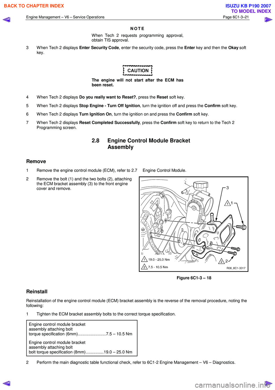
2 Remove the bolt (1) and the two bolts (2), attaching the ECM bracket assembly (3) to the front engine
cover and remove.
Figure 6C1-3 – 18
Reinstall
Reinstallation of the engine control module (ECM) bracket assembly is the reverse of the removal procedure, noting the
following:
1 Tighten the ECM bracket assembly bolts to the correct torque specification.
Engine control module bracket
assembly attaching bolt
torque specification (6mm)........................7.5 – 10.5 Nm
Engine control module bracket
assembly attaching bolt
bolt torque specification (8mm) ...............19.0 – 25.0 Nm
2 Perform the main diagnostic table functional check, refer to 6C1-2 Engine Management – V6 – Diagnostics.
BACK TO CHAPTER INDEX
TO MODEL INDEX
ISUZU KB P190 2007
Page 3732 of 6020
Powertrain Interface Module – V6 Page 6E1–71
11 Service Operations
11.1 Safety and Precautionary Measures
The following safety and precautionary
measures must be followed when servicing
and diagnosing the powertrain interface
module (PIM) System. Otherwise, personal
injury and / or improper braking system
operation may occur:
• W hen using electric welding equipment, disconnect the wiring harness connector from the PIM.
• Never disconnect or reconnect the PIM wiring harness connector when the ignition is switched ON.
• Do not touch the PIM connector pins or soldered components on the PIM circuit board to prevent possible
Electrostatic Discharge damage.
• To avoid wiring connector terminal damage, always use suitable wiring harness test leads (such as those in Tool
No, J35616) when performing tests on the PIM wiring connector.
• The PIM is extremely sensitive to Electro Magnetic Interference (EMI). Ensure the PIM wiring harness is routed
correctly and securely fitted to mounting clips when performing service procedures.
• Due to the sensitive nature of the PIM circuitry, specific wiring repair procedures have been developed. These
procedures and instructions are detailed in 8A Electrical - Body and Chassis and are the only recommended and
approved wiring repair methods.
• Ensure that all wiring harness connectors are seated correctly.
• Never disconnect the battery from the vehicle electrical system while the engine is running.
• Always disconnect the battery from the vehicle electrical system before charging.
• Do not use a fast charger for starting the vehicle.
• Ensure the battery cable terminals are secure.
• Before installing a new PIM, ensure the correct type is fitted. Always refer to the latest spare parts information.
11.2 Powertrain Interface Module
Do not touch the powertrain interface module
pins as Electrostatic Discharge (ESD) damage
may result. For further information on ESD,
refer to 1.2 Warning Caution and Notes.
When replacing the PIM, the PIM must be
reset prior to removal. Failure to perform this
procedure will result in the inability to:
• Test the PIM for warranty purposes.
• Install the PIM into other vehicles.
BACK TO CHAPTER INDEX
TO MODEL INDEX
ISUZU KB P190 2007
Page 3733 of 6020
Powertrain Interface Module – V6 Page 6E1–72
Remove
1 If replacing the PIM, reset the PIM prior to PIM removal. Refer to PIM Reset in this Section.
2 Turn the ignition switch off.
3 Remove Fuse EB-4, refer to 8A Electrical-Body and Chassis.
4 Remove the right-hand front body hinge pillar trim assembly, refer to 10 Cab.
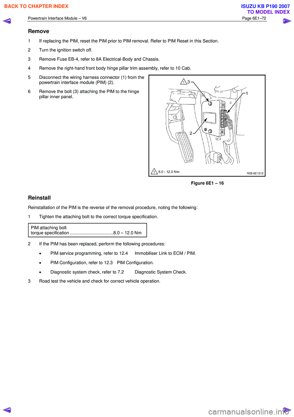
5 Disconnect the wiring harness connector (1) from the powertrain interface module (PIM) (2).
6 Remove the bolt (3) attaching the PIM to the hinge pillar inner panel.
Figure 6E1 – 16
Reinstall
Reinstallation of the PIM is the reverse of the removal procedure, noting the following:
1 Tighten the attaching bolt to the correct torque specification.
PIM attaching bolt
torque specification ...................................8.0 – 12.0 Nm
2 If the PIM has been replaced, perform the following procedures: • PIM service programming, refer to 12.4 Immobiliser Link to ECM / PIM.
• PIM Configuration, refer to 12.3 PIM Configuration.
• Diagnostic system check, refer to 7.2 Diagnostic System Check.
3 Road test the vehicle and check for correct vehicle operation.
BACK TO CHAPTER INDEX
TO MODEL INDEX
ISUZU KB P190 2007
Page 5887 of 6020
11A-36 IMMOBILIZER CONTROL SYSTEM (4JK1/4JJ1/HFV6)
Resetting and Programming
Resetting and Programming Guidelines
Notice:The security information must be programmed
when the ICU, ECM, PIM or transponder key(s) is
replaced, or transponder key(s) is added.
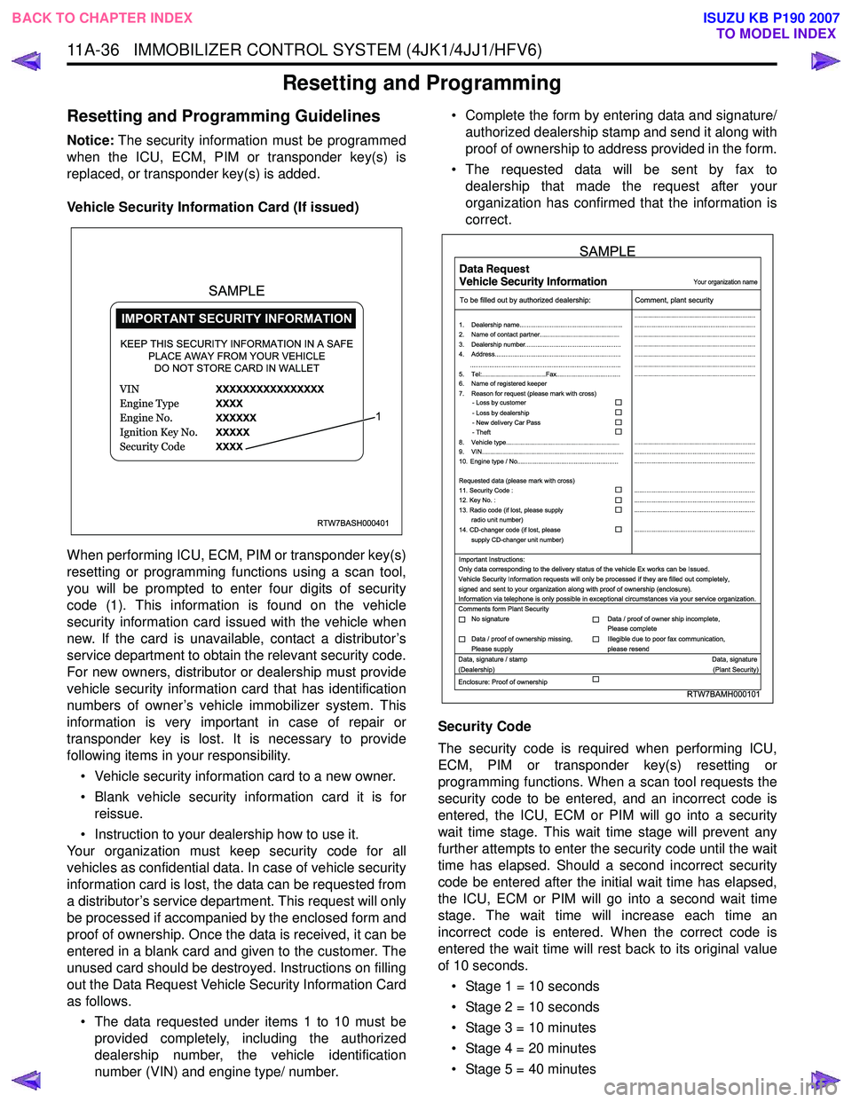
Vehicle Security Information Card (If issued)
When performing ICU, ECM, PIM or transponder key(s)
resetting or programming functions using a scan tool,
you will be prompted to enter four digits of security
code (1). This information is found on the vehicle
security information card issued with the vehicle when
new. If the card is unavailable, contact a distributor’s
service department to obtain the relevant security code.
For new owners, distributor or dealership must provide
vehicle security information card that has identification
numbers of owner’s vehicle immobilizer system. This
information is very important in case of repair or
transponder key is lost. It is necessary to provide
following items in your responsibility.
• Vehicle security information card to a new owner.
• Blank vehicle security information card it is for reissue.
• Instruction to your dealership how to use it.
Your organization must keep security code for all
vehicles as confidential data. In case of vehicle security
information card is lost, the data can be requested from
a distributor’s service department. This request will only
be processed if accompanied by the enclosed form and
proof of ownership. Once the data is received, it can be
entered in a blank card and given to the customer. The
unused card should be destroyed. Instructions on filling
out the Data Request Vehicle Security Information Card
as follows.
• The data requested under items 1 to 10 must be provided completely, including the authorized
dealership number, the vehicle identification
number (VIN) and engine type/ number. • Complete the form by entering data and signature/
authorized dealership stamp and send it along with
proof of ownership to address provided in the form.
• The requested data will be sent by fax to dealership that made the request after your
organization has confirmed that the information is
correct.
Security Code
The security code is required when performing ICU,
ECM, PIM or transponder key(s) resetting or
programming functions. When a scan tool requests the
security code to be entered, and an incorrect code is
entered, the ICU, ECM or PIM will go into a security
wait time stage. This wait time stage will prevent any
further attempts to enter the security code until the wait
time has elapsed. Should a second incorrect security
code be entered after the initial wait time has elapsed,
the ICU, ECM or PIM will go into a second wait time
stage. The wait time will increase each time an
incorrect code is entered. When the correct code is
entered the wait time will rest back to its original value
of 10 seconds.
• Stage 1 = 10 seconds
• Stage 2 = 10 seconds
• Stage 3 = 10 minutes
• Stage 4 = 20 minutes
• Stage 5 = 40 minutes
RTW7BASH000401
KEEP THIS SECURITY INFORMATION IN A SAFE PLACE AWAY FROM YOUR VEHICLEDO NOT STORE CARD IN WALLET
1
SAMPLE
RTW7BAMH000101
Your organization name
To be filled out by authorized dealership: Comment, plant security
1. Dealership name.......................................................... ....................................................................
....................................................................
....................................................................
....................................................................
....................................................................
....................................................................
....................................................................
....................................................................
.................................................................... ....................................................................
....................................................................
....................................................................
....................................................................
....................................................................
2. Name of contact partner.............................................
6. Name of registered keeper
7. Reason for request (please mark with cross)
3. Dealership number......................................................
4. Address.......................................................................
8. Vehicle type................................................................
9. VIN................................................................................
10. Engine type / No.........................................................
11. Security Code :
12. Key No. :
13. Radio code (if lost, please supply radio unit number)
14. CD-changer code (if lost, please
supply CD-changer unit number)
Requested data (please mark with cross)
5. Tel:....................................Fax....................................
.....................................................................................
- Loss by customer
- Loss by dealership
- New delivery Car Pass
- Theft
Important Instructions:
Comments form Plant Security
Data, signature / stamp Data, signature
(Dealership) (Plant Security)
Enclosure: Proof of ownership Only data corresponding to the delivery status of the vehicle Ex works can be Issued.
Vehicle Security Information requests will only be processed if they are filled out completely,
signed and sent to your organization along with proof of ownership (enclosure).
Information via telephone is only possible in exceptional circumstances via your service organization.
No signature Data / proof of owner ship incomplete,
Please complete
Data / proof of ownership missing,
Please supply Illegible due to poor fax communication,
please resend
SAMPLE
BACK TO CHAPTER INDEX TO MODEL INDEX
ISUZU KB P190 2007
Page 5899 of 6020
IMMOBILIZER SYSTEM (C24SE, 4JA1-T) 11A-1
IMMOBILIZER SYSTEM
(C24SE, 4JA1-T)
CONTENTS
Service Precaution .................................................. 11A-2
General Description ................................................ 11A-3
W hat happens without proper transponder
operation? ........................................................... 11A-5
No proper transponder is available, what
should be done for the system? ...................... 11A-5
Caution to the operation ..................................... 11A-5
Summary of operation ......................................... 11A-5
W hat your organization should provide for
your customer .................................................... 11A-5
Car Pass .............................................................. 11A-5
Security code management .............................. 11A-5
Essential tool (Scan tool : Tech-2) .................. 11A-5
Circuit Diagram .................................................. 11A-6
Parts Location .......................................................... 11A-8
Immobilizer control unit (ICU); For Electronic
Control Engine (C24SE) .................................... 11A-9
Pin-outs; For Electronic Control Engine
(C24SE) ............................................................... 11A-10
Immobilizer control unit (ICU); Mechanical
Control Engine (4JA1-T) ...................................11A-11
Immobilizer coil (Antenna) ....................................11A-13
Transponder (Key) ............................................11A-13
Check engine lamp ...........................................11A-13
Engine control module (ECM) ...........................11A-13
Car Pass Card ...................................................11A-14 Loss of car pass card .......................................... 11A-14
Instructions on Filling Out the form "Data
request, car pass" ............................................. 11A-14
Important Instructions ........................................ 11A-15
lmportant information on Programming ..............11A-17
Security code ....................................................... 11A-17
Entering a code ................................................... 11A-17
Transponder (Key) ............................................. 11A-17
Tech-2 Scan Tool .................................................. 11A-18
Operating Procedure .......................................... 11A-18
Menu .................................................................... 11A-19
DTC ...................................................................... 11A-19
Clear DTC Information ......................................11A-19
Tech-2 Data Display .......................................... 11A-19
Check Vehicle Identification Number (VIN) ....11A-19
Reset Immobilizer (Reset Immobilizer
Control Unit) ....................................................... 11A-19
Reset Engine Control Module (Reset ECM) ..11A-20
Erase transponder key ......................................11A-20
Programming Immobilizer Function ................11A-21
Programming ICU .............................................. 11A-22
Programming ECM ............................................ 11A-23
Programming ICU and ECM .............................11A-24
Transponder program ........................................ 11A-24
Data List .............................................................. 11A-26
Diagnostic procedure ............................................ 11A-27
Clearing Diagnostic Trouble Codes ....................11A-27
Verifying Vehicle Repair .......................................11A-27
Diagnostic Aids ...................................................... 11A-27
Check the condition for system parts ..............11A-27
Check the Electro-Magnetic Interference
(EMI) ................................................................... 11A-27
Check the other items .......................................11A-27
Check the operation ........................................... 11A-27
Diagnostic Trouble Code (DTC) list ....................11A-28
IMMOBILIZER SYSTEM CHECK .......................11A-30
NO IMMOBILIZER W ARNING LAMP ................11A-32
CHECK IMMOBILIZER W ARNING LAMP O
STEADY ................................................................ 11A-33
B0001 REPLACE ELECTRONIC CONTROL
UNIT (ECU) (IMMOBILIZER FAULT) ................11A-34
B0002 IMMOBILIZER NOT PROGRAMMED ...11A-35
B0003 TRANSPONDER KEY PROBLEM .........11A-36
B0004 IMMOBILIZER COIL CIRCUIT
(ANTENNA COIL FAULT) ...................................11A-38
B0005 COMMUNICATION LINE W VOLTAGE
LOW ....................................................................... 11A-39
B0006 COMMUNICATION LINE W VOLTAGE
HIGH ...................................................................... 11A-40
BACK TO CHAPTER INDEX
TO MODEL INDEX
ISUZU KB P190 2007