2007 ISUZU KB P190 coolant reservoir
[x] Cancel search: coolant reservoirPage 3148 of 6020
Engine Cooling – V6 Engine Page 6B1–13
2.6 Coolant Filler Cap
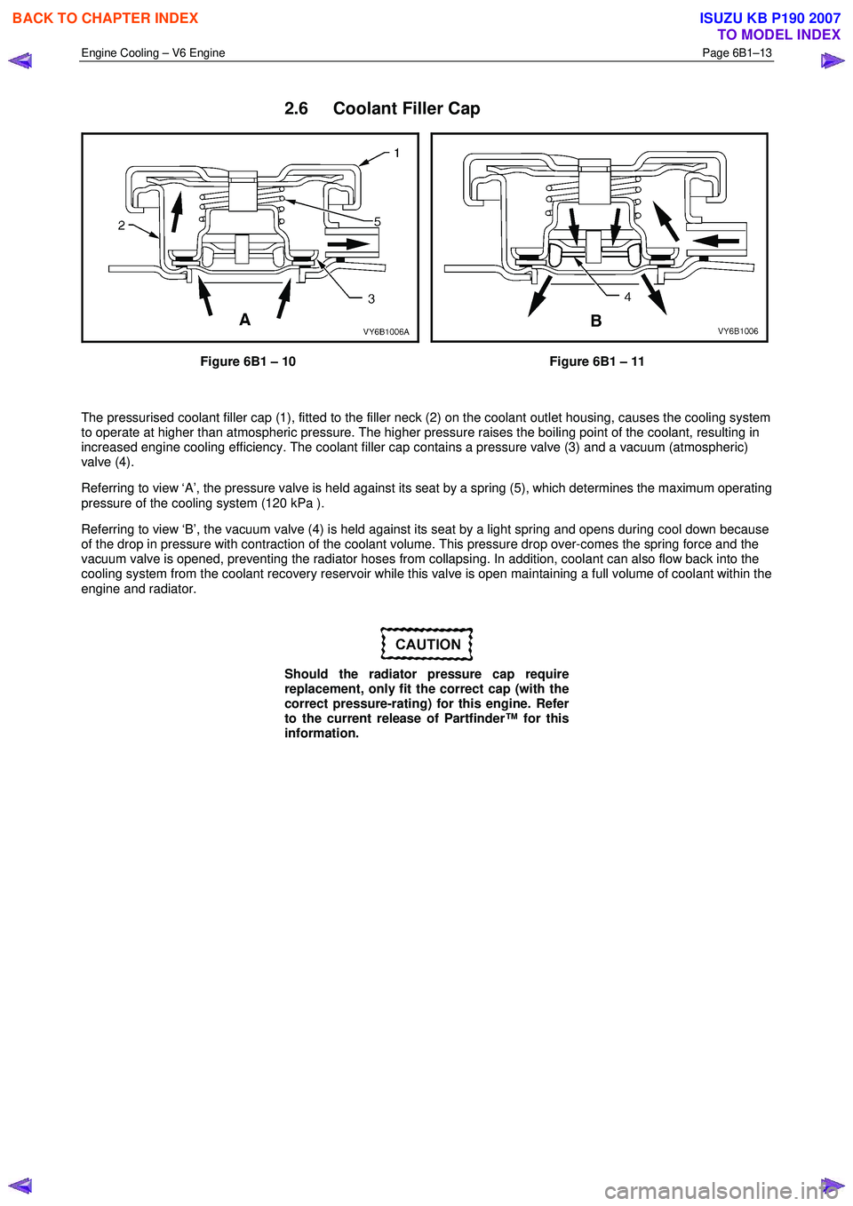
Figure 6B1 – 10 Figure 6B1 – 11
The pressurised coolant filler cap (1), fitted to the filler neck (2) on the coolant outlet housing, causes the cooling system
to operate at higher than atmospheric pressure. The higher pressure raises the boiling point of the coolant, resulting in
increased engine cooling efficiency. The coolant filler cap contains a pressure valve (3) and a vacuum (atmospheric)
valve (4).
Referring to view ‘A’, the pressure valve is held against its seat by a spring (5), which determines the maximum operating
pressure of the cooling system (120 kPa ).
Referring to view ‘B’, the vacuum valve (4) is held against its seat by a light spring and opens during cool down because
of the drop in pressure with contraction of the coolant volume. This pressure drop over-comes the spring force and the
vacuum valve is opened, preventing the radiator hoses from collapsing. In addition, coolant can also flow back into the
cooling system from the coolant recovery reservoir while this valve is open maintaining a full volume of coolant within the
engine and radiator.
Should the radiator pressure cap require
replacement, only fit the correct cap (with the
correct pressure-rating) for this engine. Refer
to the current release of Partfinder™ for this
information.
BACK TO CHAPTER INDEX
TO MODEL INDEX
ISUZU KB P190 2007
Page 3149 of 6020
Engine Cooling – V6 Engine Page 6B1–14
2.7 Coolant Recovery Reservoir
The coolant is maintained at the ideal level in the radiator by the coolant filler cap and the coolant recovery reservoir,
resulting in increased cooling efficiency.
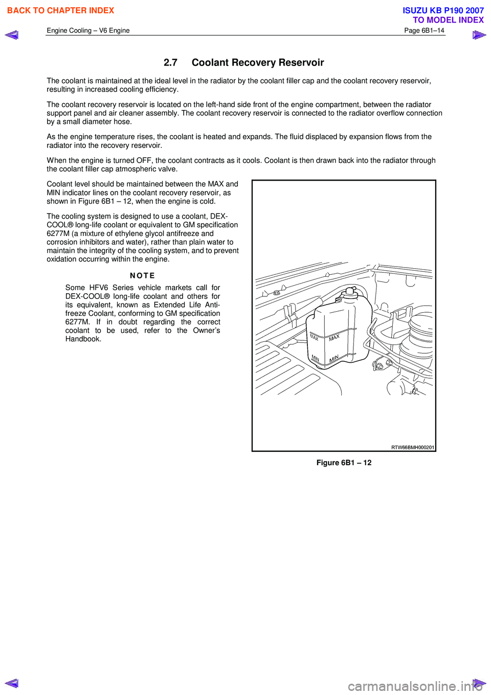
The coolant recovery reservoir is located on the left-hand side front of the engine compartment, between the radiator
support panel and air cleaner assembly. The coolant recovery reservoir is connected to the radiator overflow connection
by a small diameter hose.
As the engine temperature rises, the coolant is heated and expands. The fluid displaced by expansion flows from the
radiator into the recovery reservoir.
W hen the engine is turned OFF, the coolant contracts as it cools. Coolant is then drawn back into the radiator through
the coolant filler cap atmospheric valve.
Coolant level should be maintained between the MAX and
MIN indicator lines on the coolant recovery reservoir, as
shown in Figure 6B1 – 12, when the engine is cold.
The cooling system is designed to use a coolant, DEX-
COOL® long-life coolant or equivalent to GM specification
6277M (a mixture of ethylene glycol antifreeze and
corrosion inhibitors and water), rather than plain water to
maintain the integrity of the cooling system, and to prevent
oxidation occurring within the engine.
NOTE
Some HFV6 Series vehicle markets call for
DEX-COOL® long-life coolant and others for
its equivalent, known as Extended Life Anti-
freeze Coolant, conforming to GM specification
6277M. If in doubt regarding the correct
coolant to be used, refer to the Owner’s
Handbook.
Figure 6B1 – 12
BACK TO CHAPTER INDEX
TO MODEL INDEX
ISUZU KB P190 2007
Page 3151 of 6020

Engine Cooling – V6 Engine Page 6B1–16
3 Service Operations
3.1 Service Notes
Safety
• To avoid serious personal injury, never
remove the coolant filler pressure cap on
the coolant outlet housing when the
engine is hot, even if the cooling system
should require filling. Sudden release of
cooling system pressure is very
dangerous.
• The vehicle is fitted with an electric
radiator cooling fan. When working around
the engine compartment, keep clear of the
fan as it may start without warning.
Before removing the coolant filler cap, allow the engine to cool, then place a shop rag over the coolant filler cap and then
slowly turn the cap anticlockwise, approximately 1½ turns, until the pressure relief position is reached. The pressure
relief position will allow any remaining pressure within the system to escape into the coolant recovery reservoir. Continue
to rotate the cap anticlockwise until the cap can be safely removed.
Periodic Servicing
The cooling system requires little attention except for maintaining the coolant to the correct level in the recovery reservoir
and periodic servicing at the time or distance intervals as outlined in 0B Lubrication and Service.
Periodic servicing includes:
1 Checking coolant level. Refer to 3.3 Draining and Filling Cooling System in this Section.
2 Checking coolant concentration. Refer to 3.2 Coolant Maintenance – Testing Coolant Concentration in this Section.
3 Pressure test cooling system and coolant filler cap. Refer to 3.7 Pressure Testing in this Section.
4 Tighten hose clamps and inspect all hoses. Refer to 3.6 Coolant Hoses in this Section. Replace hoses if swollen or deteriorated.
Always wear protective safety glasses when
working with spring type hose clamps. Failure
to do so could result in eye injury.
5 Clean out cooling system, refer to 3.4 Cleaning Cooling System – Cooling System Flush, in this Section and refill. Refer to 3.3 Draining and Filling Cooling System in this Section.
Environmental Issues
To reduce environmental impact and maintenance cost, whenever the coolant is drained from any engine, the service
records are to be checked to determine when the coolant was last changed. If more than six months life is left before the
next coolant change, then the following procedure is to be followed:
1 W hen draining the coolant from the engine, use a clean container to hold at least 12 litres of coolant and ensure that the coolant is not contaminated in the draining process.
2 After repairs have been completed, refill the engine cooling system with the drained coolant.
BACK TO CHAPTER INDEX
TO MODEL INDEX
ISUZU KB P190 2007
Page 3153 of 6020
Engine Cooling – V6 Engine Page 6B1–18
Topping Up the Cooling System
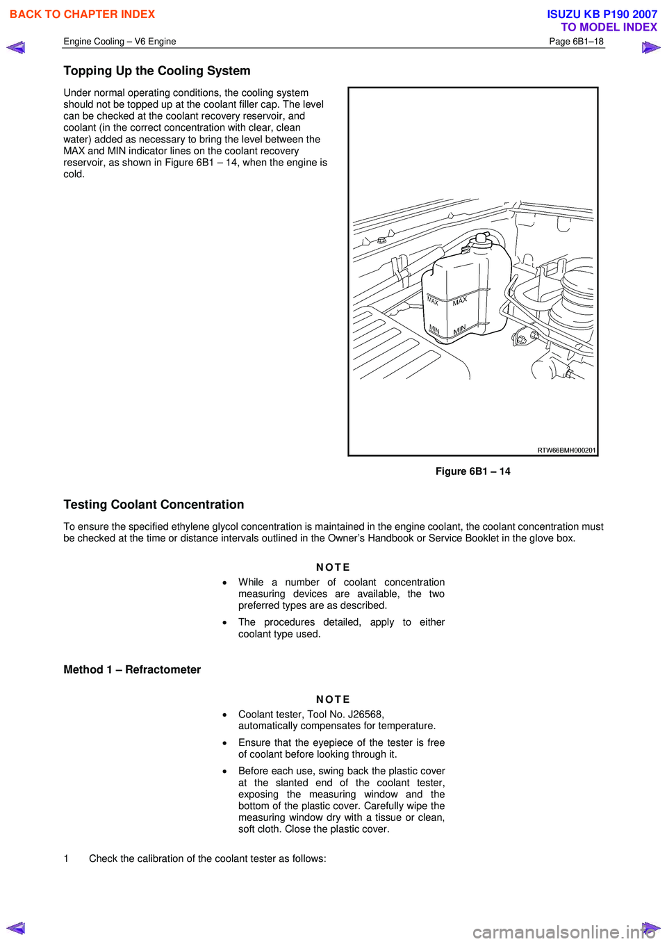
Under normal operating conditions, the cooling system
should not be topped up at the coolant filler cap. The level
can be checked at the coolant recovery reservoir, and
coolant (in the correct concentration with clear, clean
water) added as necessary to bring the level between the
MAX and MIN indicator lines on the coolant recovery
reservoir, as shown in Figure 6B1 – 14, when the engine is
cold.
Figure 6B1 – 14
Testing Coolant Concentration
To ensure the specified ethylene glycol concentration is maintained in the engine coolant, the coolant concentration must
be checked at the time or distance intervals outlined in the Owner’s Handbook or Service Booklet in the glove box.
NOTE
• While a number of coolant concentration
measuring devices are available, the two
preferred types are as described.
• The procedures detailed, apply to either
coolant type used.
Method 1 – Refractometer
NOTE
• Coolant tester, Tool No. J26568,
automatically compensates for temperature.
• Ensure that the eyepiece of the tester is free
of coolant before looking through it.
• Before each use, swing back the plastic cover
at the slanted end of the coolant tester,
exposing the measuring window and the
bottom of the plastic cover. Carefully wipe the
measuring window dry with a tissue or clean,
soft cloth. Close the plastic cover.
1 Check the calibration of the coolant tester as follows:
BACK TO CHAPTER INDEX
TO MODEL INDEX
ISUZU KB P190 2007
Page 3155 of 6020
Engine Cooling – V6 Engine Page 6B1–20
COOLANT CONCENTRATION
Litres Of Coolant To Be Added
Concentration Reading % Automatic Transmission Manual Transmission
0 4.95 5.15
5 4.46 4.62
10 3.96 4.12
15 3.47 3.61
20 2.97 3.08
25 2.48 2.57
30 1.98 2.01
35 1.48 1.54
40 0.99 1.05
45 0.50 0.52
50 0 0
NOTE
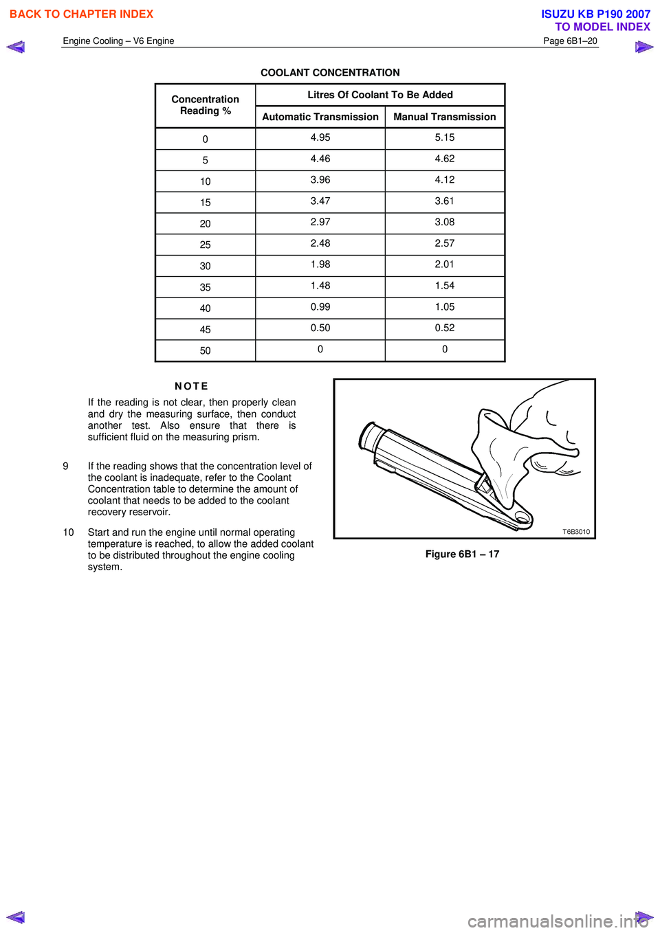
If the reading is not clear, then properly clean
and dry the measuring surface, then conduct
another test. Also ensure that there is
sufficient fluid on the measuring prism.
9 If the reading shows that the concentration level of the coolant is inadequate, refer to the Coolant
Concentration table to determine the amount of
coolant that needs to be added to the coolant
recovery reservoir.
10 Start and run the engine until normal operating temperature is reached, to allow the added coolant
to be distributed throughout the engine cooling
system.
Figure 6B1 – 17
BACK TO CHAPTER INDEX
TO MODEL INDEX
ISUZU KB P190 2007
Page 3159 of 6020
Engine Cooling – V6 Engine Page 6B1–24
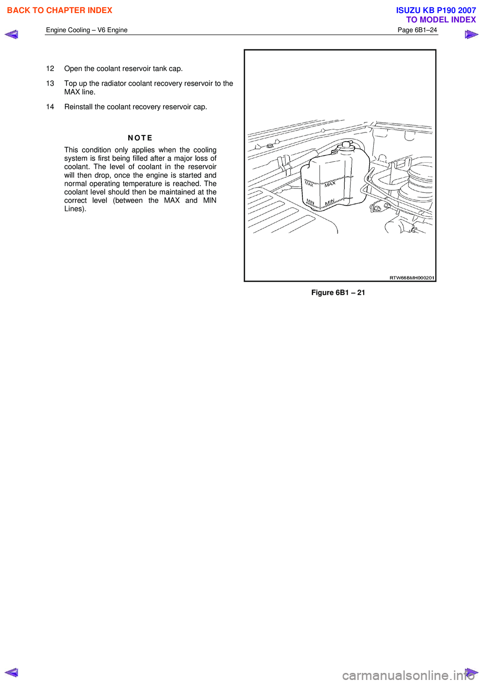
12 Open the coolant reservoir tank cap.
13 Top up the radiator coolant recovery reservoir to the MAX line.
14 Reinstall the coolant recovery reservoir cap.
NOTE
This condition only applies when the cooling
system is first being filled after a major loss of
coolant. The level of coolant in the reservoir
will then drop, once the engine is started and
normal operating temperature is reached. The
coolant level should then be maintained at the
correct level (between the MAX and MIN
Lines).
Figure 6B1 – 21
BACK TO CHAPTER INDEX
TO MODEL INDEX
ISUZU KB P190 2007
Page 3161 of 6020
Engine Cooling – V6 Engine Page 6B1–26
10 Pressure test the cooling system. Refer to 3.7 Pressure Testing in this Section.
Engine
Refer to ‘
‘‘
‘
Environmental Issues ’
’’
’
in 3.1
Service Notes, before draining the coolant.
1 Drain the cooling system. Refer to 3.3 Draining and Filling Cooling System in this Section.
Always wear eye protection when working
with spring-type hose clamps. Failure to do
so may result in eye injury.
2 Remove the upper and lower radiator hoses from the coolant outlet housing and coolant inlet pipe connections. Refer to Figure 6B1 – 22.
3 Remove the thermostat housing from the rear of the engine block. Refer to 6A1 Engine Mechanical – V6..
4 Remove the thermostat from the thermostat housing and reinstall the housing to the rear of the intake manifold. Refer to 3.8 Thermostat in this Section.
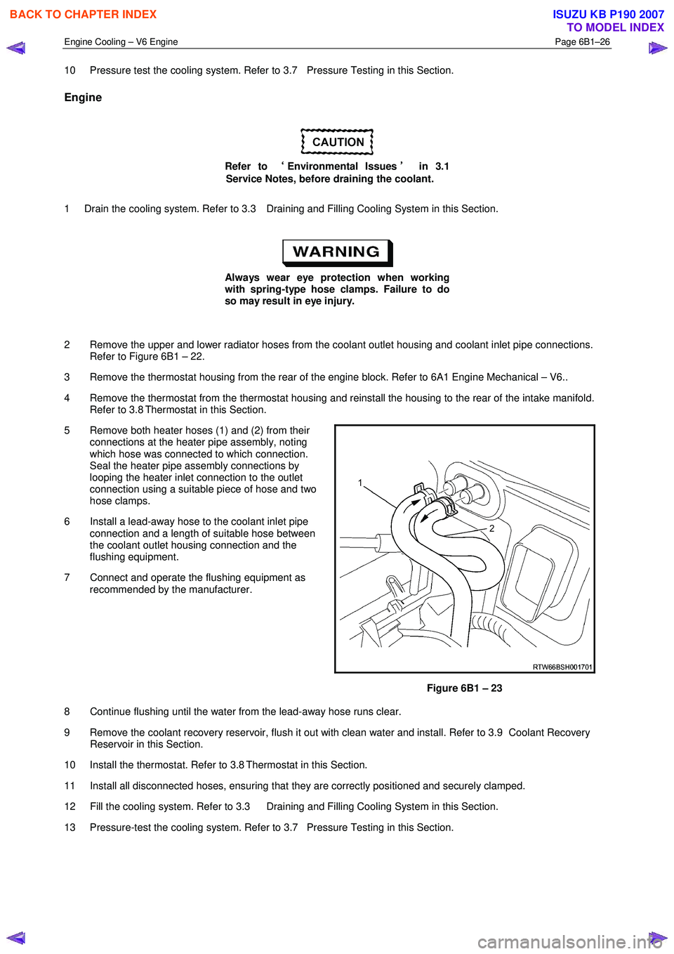
5 Remove both heater hoses (1) and (2) from their connections at the heater pipe assembly, noting
which hose was connected to which connection.
Seal the heater pipe assembly connections by
looping the heater inlet connection to the outlet
connection using a suitable piece of hose and two
hose clamps.
6 Install a lead-away hose to the coolant inlet pipe connection and a length of suitable hose between
the coolant outlet housing connection and the
flushing equipment.
7 Connect and operate the flushing equipment as recommended by the manufacturer.
Figure 6B1 – 23
8 Continue flushing until the water from the lead-away hose runs clear.
9 Remove the coolant recovery reservoir, flush it out with clean water and install. Refer to 3.9 Coolant Recovery Reservoir in this Section.
10 Install the thermostat. Refer to 3.8 Thermostat in this Section.
11 Install all disconnected hoses, ensuring that they are correctly positioned and securely clamped.
12 Fill the cooling system. Refer to 3.3 Draining and Filling Cooling System in this Section.
13 Pressure-test the cooling system. Refer to 3.7 Pressure Testing in this Section.
BACK TO CHAPTER INDEX
TO MODEL INDEX
ISUZU KB P190 2007
Page 3174 of 6020
Engine Cooling – V6 Engine Page 6B1–39
18 Check for coolant leaks. Refer to 3.7 Pressure Testing in this Section.
19 Install the radiator shroud.
20 Install the engine dress covers. Refer to 6A1 Engine Mechanical.
21 Reconnect battery ground lead. Refer to 8A_ Electrical Body & Chassis.
22 Road test the vehicle to check for correct operation.
3.9 Coolant Recovery Reservoir
Remove
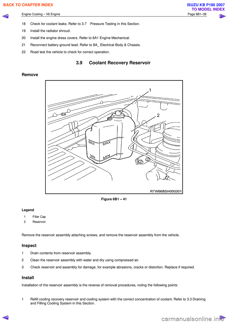
Figure 6B1 – 41
Legend
1 Filler Cap
2 Reservoir
Remove the reservoir assembly attaching screws, and remove the reservoir assembly from the vehicle.
Inspect
1 Drain contents from reservoir assembly.
2 Clean the reservoir assembly with water and dry using compressed air.
3 Check reservoir and assembly for damage, for example abrasions, cracks or distortion. Replace if required.
Install
Installation of the reservoir assembly is the reverse of removal procedures, noting the following points:
1 Refill cooling recovery reservoir and cooling system with the correct concentration of coolant. Refer to 3.3 Draining and Filling Cooling System in this Section.
BACK TO CHAPTER INDEX
TO MODEL INDEX
ISUZU KB P190 2007