2007 ISUZU KB P190 Diagram
[x] Cancel search: DiagramPage 1589 of 6020
ENGINE ELECTRICAL (4JK1/4JJ1) 6D-1
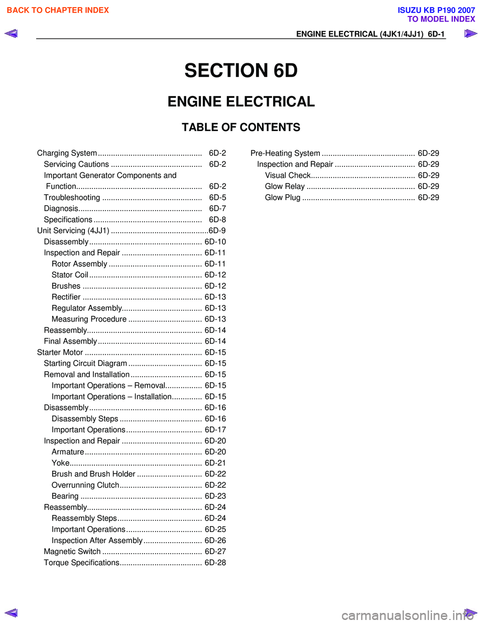
SECTION 6D
ENGINE ELECTRICAL
TABLE OF CONTENTS
Charging System ................................................ 6D-2
Servicing Cautions .......................................... 6D-2
Important Generator Components and
Function.......................................................... 6D-2
Troubleshooting .............................................. 6D-5
Diagnosis......................................................... 6D-7
Specifications .................................................. 6D-8
Unit Se rv ic ing (4 JJ 1) ....................................... .... ..6D -9
Disassembly .................................................... 6D-10
Inspection and Repair ..................................... 6D-11 Rotor Assembly ........................................... 6D-11
Stator Coil .................................................... 6D-12
Brushes ....................................................... 6D-12
Rectifier ....................................................... 6D-13
Regulator Assembly..................................... 6D-13
Measuring Procedure .................................. 6D-13
Reassembly..................................................... 6D-14
Final Assembly ................................................ 6D-14
Starter Motor ...................................................... 6D-15 Starting Circuit Diagram .................................. 6D-15
Removal and Installation ................................. 6D-15 Important Operations – Removal................. 6D-15
Important Operations – Installation.............. 6D-15
Disassembly .................................................... 6D-16 Disassembly Steps ...................................... 6D-16
Important Operations ................................... 6D-17
Inspection and Repair ..................................... 6D-20 Armature ...................................................... 6D-20
Yoke............................................................. 6D-21
Brush and Brush Holder .............................. 6D-22
Overrunning Clutch...................................... 6D-22
Bearing ........................................................ 6D-23
Reassembly..................................................... 6D-24 Reassembly Steps ....................................... 6D-24
Important Operations ................................... 6D-25
Inspection After Assembly ........................... 6D-26
Magnetic Switch .............................................. 6D-27
Torque Specifications...................................... 6D-28
Pre-Heating System ........................................... 6D-29 Inspection and Repair ..................................... 6D-29 Visual Check................................................ 6D-29
Glow Relay .................................................. 6D-29
Glow Plug .................................................... 6D-29
BACK TO CHAPTER INDEX
TO MODEL INDEX
ISUZU KB P190 2007
Page 1603 of 6020
ENGINE ELECTRICAL (4JK1/4JJ1) 6D-15
Starter Motor
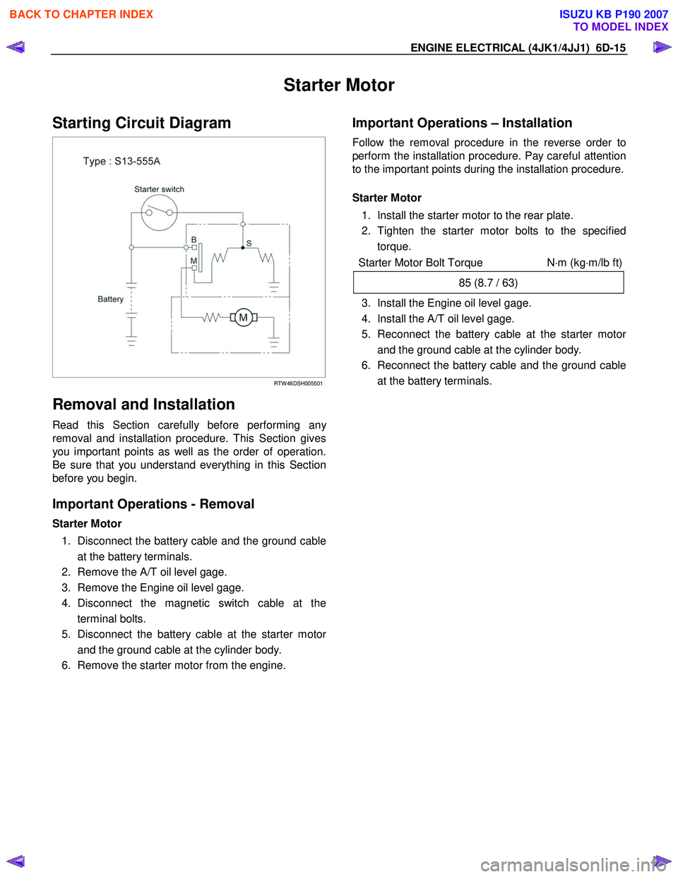
Starting Circuit Diagram
RTW 46DSH005501
Removal and Installation
Read this Section carefully before performing any
removal and installation procedure. This Section gives
you important points as well as the order of operation.
Be sure that you understand everything in this Section
before you begin.
Important Operations - Removal
Starter Motor
1. Disconnect the battery cable and the ground cable at the battery terminals.
2. Remove the A/T oil level gage.
3. Remove the Engine oil level gage.
4. Disconnect the magnetic switch cable at the terminal bolts.
5. Disconnect the battery cable at the starter moto
r
and the ground cable at the cylinder body.
6. Remove the starter motor from the engine.
Important Operations – Installation
Follow the removal procedure in the reverse order to
perform the installation procedure. Pay careful attention
to the important points during the installation procedure.
Starter Motor
1. Install the starter motor to the rear plate.
2. Tighten the starter motor bolts to the specified torque.
Starter Motor Bolt Torque N⋅m (kg ⋅m/lb ft)
85 (8.7 / 63)
3. Install the Engine oil level gage.
4. Install the A/T oil level gage.
5. Reconnect the battery cable at the starter moto
r
and the ground cable at the cylinder body.
6. Reconnect the battery cable and the ground cable at the battery terminals.
BACK TO CHAPTER INDEX
TO MODEL INDEX
ISUZU KB P190 2007
Page 1618 of 6020

ENGINE CONTROL SYSTEM (4JK1/4JJ1) 6E-1
SECTION 6E
ENGINE CONTROL SYSTEM(4JK1/4JJ1)
TABLE OF CONTENTS
Specifications . . . . . . . . . . . . . . . . . . . . . . . . . . . . 6E-3 Temperature vs Resistance . . . . . . . . . . . . . . . . 6E-3
Altitude vs Barometric Pressure . . . . . . . . . . . . . 6E-3
Diagnostic Trouble Code (DTC) Type Definitions . . . . . . . . . . . . . . . . . . . . . . . . . . . . . 6E-4
Diagnostic Trouble Code (DTC) List . . . . . . . . . 6E-4
Schematic and Rounting Diagrams. . . . . . . . . . . . 6E-9 Fuel System Routing Diagram . . . . . . . . . . . . . . 6E-9
Vacuum Hose Routing Diagram . . . . . . . . . . . . . 6E-9
Engine Controls Schematics . . . . . . . . . . . . . . 6E-10
Component Locator. . . . . . . . . . . . . . . . . . . . . . . 6E-27 Engine Controls Component Views . . . . . . . . . 6E-27
Engine Control Module (ECM) Connector End Views . . . . . . . . . . . . . . . . . . . . . . . . . . . . 6E-30
Engine Control Connector End Views . . . . . . . 6E-33
Diagnostic Information and Procedures . . . . . . . 6E-42 Engine Control System Check Sheet . . . . . . . . 6E-42
Diagnostic Starting Point - Engine Controls . . . 6E-43
Diagnostic System Check - Engine Controls . . 6E-44
Scan Tool Data List . . . . . . . . . . . . . . . . . . . . . 6E-46
Scan Tool Data Definitions . . . . . . . . . . . . . . . . 6E-49
Scan Tool Output Controls . . . . . . . . . . . . . . . . 6E-54
Scan Tool Does Not Power Up. . . . . . . . . . . . . 6E-55
Scan Tool Does Not Communicate with CAN Device. . . . . . . . . . . . . . . . . . . . . . . . . . . 6E-56
Lost Communication with The Engine Control Module (ECM) . . . . . . . . . . . . . . . . . . 6E-59
Engine Cranks but Does Not Run . . . . . . . . . . 6E-62
DTC P0016 (Flash Code 16) . . . . . . . . . . . . . . 6E-68
DTC P0045 (Flash Code 33) . . . . . . . . . . . . . . 6E-70
DTC P0087 (Flash Code 225) . . . . . . . . . . . . . 6E-72
DTC P0088 (Flash Code 118) . . . . . . . . . . . . . 6E-77
DTC P0089 (Flash Code 151) . . . . . . . . . . . . . 6E-82
DTC P0091 or P0092 (Flash Code 247) . . . . . 6E-85
DTC P0093 (Flash Code 227) . . . . . . . . . . . . . 6E-88
DTC P0101 (Flash Code 92) . . . . . . . . . . . . . . 6E-93
DTC P0102 or P0103 (Flash Code 91) . . . . . . 6E-96
DTC P0107 or P0108 (Flash Code 32) . . . . . 6E-100
DTC P0112 or P0113 (Flash Code 22) . . . . . 6E-104
DTC P0116 (Flash Code 23) . . . . . . . . . . . . . 6E-108
DTC P0117 or P0118 (Flash Code 23) . . . . . 6E-110
DTC P0122 or P0123 (Flash Code 43) . . . . . 6E-114
DTC P0182 or P0183 (Flash Code 211) . . . . 6E-118
DTC P0192 or P0193 (Flash Code 245) . . . . 6E-122
DTC P0201, P0202, P0203 or P0204 (Flash Code 271, 272, 273 or 274) . . . . . . . . 6E-126
DTC P0217 (Flash Code 542) . . . . . . . . . . . . 6E-133
DTC P0219 (Flash Code 543) . . . . . . . . . . . . 6E-135
DTC P0231 or P0232 (Flash Code 69) . . . . . 6E-137
DTC P0234 (Flash Code 42) . . . . . . . . . . . . . 6E-140 DTC P0299 (Flash Code 65) . . . . . . . . . . . . . 6E-143
DTC P0335 (Flash Code 15) . . . . . . . . . . . . . 6E-146
DTC P0336 (Flash Code 15) . . . . . . . . . . . . . 6E-149
DTC P0340 (Flash Code 14) . . . . . . . . . . . . . 6E-151
DTC P0341 (Flash Code 14) . . . . . . . . . . . . . 6E-154
DTC P0380 (Flash Code 66) . . . . . . . . . . . . . 6E-156
DTC P0401 (Flash Code 93) . . . . . . . . . . . . . 6E-159
DTC P0403 (Flash Code 37) . . . . . . . . . . . . . 6E-161
DTC P0404 (Flash Code 45) . . . . . . . . . . . . . 6E-164
DTC P0405 or P0406 (Flash Code 44) . . . . . 6E-166
DTC P0500 (Flash Code 25) . . . . . . . . . . . . . 6E-170
DTC P0501 (Flash Code 25) . . . . . . . . . . . . . 6E-174
DTC P0512 (Flash Code 417) . . . . . . . . . . . . 6E-176
DTC P0562 or P0563 (Flash Code 35) . . . . . 6E-178
DTC P0565 (Flash Code 515) . . . . . . . . . . . . 6E-181
DTC P0566 (Flash Code 516) . . . . . . . . . . . . 6E-183
DTC P0567 (Flash Code 517) . . . . . . . . . . . . 6E-185
DTC P0568 (Flash Code 518) . . . . . . . . . . . . 6E-187
DTC P0571 (Flash Code 26) . . . . . . . . . . . . . 6E-189
DTC P0601 (Flash Code 53) . . . . . . . . . . . . . 6E-192
DTC P0602 (Flash Code 154) . . . . . . . . . . . . 6E-193
DTC P0604 or P0606 (Flash Code 153 or 51) . . . . . . . . . . . . . . . . . 6E-195
DTC P0615 (Flash Code 19) . . . . . . . . . . . . . 6E-196
DTC P0633 (Flash Code 176) . . . . . . . . . . . . 6E-198
DTC P0638 (Flash Code 61) . . . . . . . . . . . . . 6E-199
DTC P0642 or P0643 (Flash Code 55) . . . . . 6E-201
DTC P0650 (Flash Code 77) . . . . . . . . . . . . . 6E-204
DTC P0652 or P0653 (Flash Code 56) . . . . . 6E-207
DTC P0661 or P0662 (Flash Code 58) . . . . . 6E-211
DTC P0698 or P0699 (Flash Code 57) . . . . . 6E-215
DTC P0700 (Flash Code 185) . . . . . . . . . . . . 6E-219
DTC P1064 or P1065 (Flash Code 247) . . . . 6E-220
DTC P1093 (Flash Code 227) . . . . . . . . . . . . 6E-224
DTC P1094 (Flash Code 226) . . . . . . . . . . . . 6E-229
DTC P1196, P1197 or P1198 (Flash Code 461) . . . . . . . . . . . . . . . . . . . . . 6E-235
DTC P124B (Flash Code 157) . . . . . . . . . . . . 6E-237
DTC P1261 (Flash Code 34) . . . . . . . . . . . . . 6E-240
DTC P1262 (Flash Code 34) . . . . . . . . . . . . . 6E-242
DTC P1404 (Flash Code 45) . . . . . . . . . . . . . 6E-244
DTC P1411, P1412 or P1413 (Flash Code 445) . . . . . . . . . . . . . . . . . . . . . 6E-246
DTC P156A or P156B (Flash Code 135) . . . . 6E-248
DTC P161B (Flash Code 179) . . . . . . . . . . . . 6E-251
DTC P1621 (Flash Code 54, 254) . . . . . . . . . 6E-253
DTC P1664 (Flash Code 76) . . . . . . . . . . . . . 6E-255
DTC P2100, P2101 or P2103 (Flash Code 446) . . . . . . . . . . . . . . . . . . . . . 6E-258
DTC P2122 or P2123 (Flash Code 121) . . . . 6E-261
BACK TO CHAPTER INDEX
TO MODEL INDEX
ISUZU KB P190 2007
Page 1626 of 6020
ENGINE CONTROL SYSTEM (4JK1/4JJ1) 6E-9
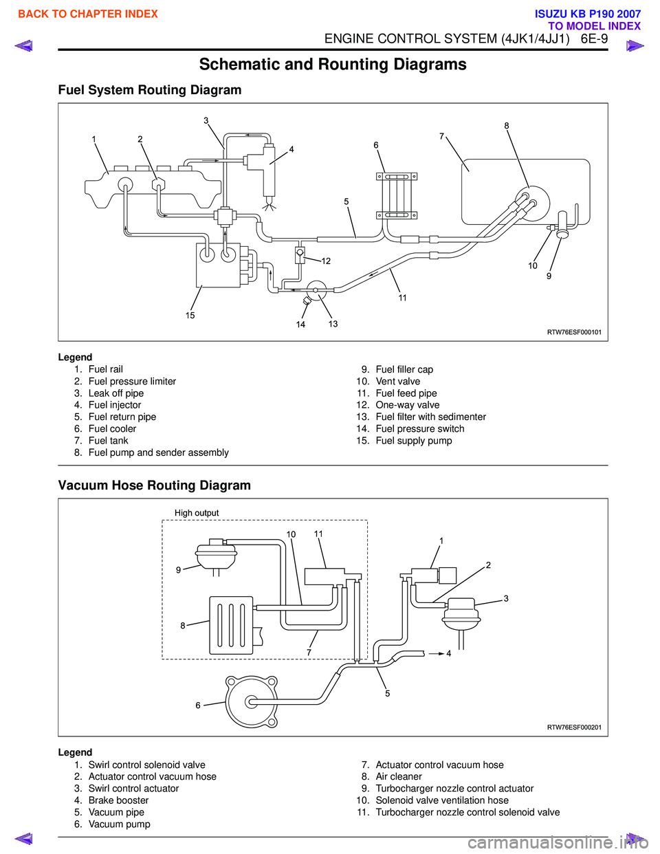
Schematic and Rounting Diagrams
Fuel System Routing Diagram
Legend1. Fuel rail
2. Fuel pressure limiter
3. Leak off pipe
4. Fuel injector
5. Fuel return pipe
6. Fuel cooler
7. Fuel tank
8. Fuel pump and sender assembly 9. Fuel filler cap
10. Vent valve 11. Fuel feed pipe
12. One-way valve
13. Fuel filter with sedimenter
14. Fuel pressure switch
15. Fuel supply pump
Vacuum Hose Routing Diagram
Legend
1. Swirl control solenoid valve
2. Actuator control vacuum hose
3. Swirl control actuator
4. Brake booster
5. Vacuum pipe
6. Vacuum pump 7. Actuator control vacuum hose
8. Air cleaner
9. Turbocharger nozzle control actuator
10. Solenoid valve ventilation hose 11. Turbocharger nozzle control solenoid valve
RTW76ESF000101
12 3
4
5
117
8
9
10
14
13
12
15
6
RTW76ESF000201
1 2
4
5
6
9
8
3
7
11
High output10
BACK TO CHAPTER INDEX
TO MODEL INDEX
ISUZU KB P190 2007
Page 1688 of 6020
ENGINE CONTROL SYSTEM (4JK1/4JJ1) 6E-71
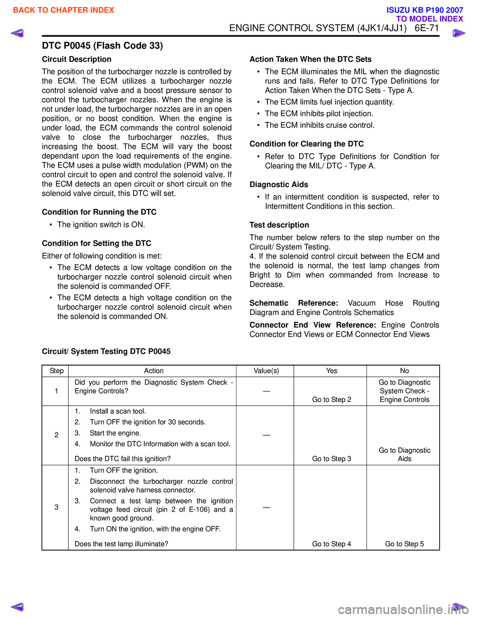
DTC P0045 (Flash Code 33)
Circuit Description
The position of the turbocharger nozzle is controlled by
the ECM. The ECM utilizes a turbocharger nozzle
control solenoid valve and a boost pressure sensor to
control the turbocharger nozzles. When the engine is
not under load, the turbocharger nozzles are in an open
position, or no boost condition. When the engine is
under load, the ECM commands the control solenoid
valve to close the turbocharger nozzles, thus
increasing the boost. The ECM will vary the boost
dependant upon the load requirements of the engine.
The ECM uses a pulse width modulation (PWM) on the
control circuit to open and control the solenoid valve. If
the ECM detects an open circuit or short circuit on the
solenoid valve circuit, this DTC will set.
Condition for Running the DTC • The ignition switch is ON.
Condition for Setting the DTC
Either of following condition is met: • The ECM detects a low voltage condition on the turbocharger nozzle control solenoid circuit when
the solenoid is commanded OFF.
• The ECM detects a high voltage condition on the turbocharger nozzle control solenoid circuit when
the solenoid is commanded ON. Action Taken When the DTC Sets
• The ECM illuminates the MIL when the diagnostic runs and fails. Refer to DTC Type Definitions for
Action Taken When the DTC Sets - Type A.
• The ECM limits fuel injection quantity.
• The ECM inhibits pilot injection.
• The ECM inhibits cruise control.
Condition for Clearing the DTC • Refer to DTC Type Definitions for Condition for Clearing the MIL/ DTC - Type A.
Diagnostic Aids • If an intermittent condition is suspected, refer to Intermittent Conditions in this section.
Test description
The number below refers to the step number on the
Circuit/ System Testing.
4. If the solenoid control circuit between the ECM and
the solenoid is normal, the test lamp changes from
Bright to Dim when commanded from Increase to
Decrease.
Schematic Reference: Vacuum Hose Routing
Diagram and Engine Controls Schematics
Connector End View Reference: Engine Controls
Connector End Views or ECM Connector End Views
Circuit/ System Testing DTC P0045
Step Action Value(s)Yes No
1 Did you perform the Diagnostic System Check -
Engine Controls? —
Go to Step 2 Go to Diagnostic
System Check -
Engine Controls
2 1. Install a scan tool.
2. Turn OFF the ignition for 30 seconds.
3. Start the engine.
4. Monitor the DTC Information with a scan tool.
Does the DTC fail this ignition? —
Go to Step 3 Go to Diagnostic
Aids
3 1. Turn OFF the ignition.
2. Disconnect the turbocharger nozzle control solenoid valve harness connector.
3. Connect a test lamp between the ignition voltage feed circuit (pin 2 of E-106) and a
known good ground.
4. Turn ON the ignition, with the engine OFF.
Does the test lamp illuminate? —
Go to Step 4 Go to Step 5
BACK TO CHAPTER INDEX
TO MODEL INDEX
ISUZU KB P190 2007
Page 1691 of 6020

6E-74 ENGINE CONTROL SYSTEM (4JK1/4JJ1)
DTC P0087 (Flash Code 225)
Description
The common rail fuel system is comprised of two fuel
pressure sections: a suction side between the fuel tank
and the fuel supply pump and a high-pressure side
between the fuel supply pump and the fuel injectors.
Fuel is drawn from the fuel tank via a feed pump and
then pumped into the fuel rail by two plungers, all of
which are internal to the fuel supply pump. This high
pressure is regulated by the ECM using the fuel rail
pressure (FRP) regulator dependant upon values from
the FRP sensor attached to the fuel rail. In case of fuel
rail overpressure, a pressure limiter valve threaded into
the fuel rail will open to release overpressure and
return fuel back to the fuel tank. If the ECM detects that
the fuel rail pressure went excessively high, then
sharply decreased, this DTC will set indicating high fuel
pressure, which activated the pressure limiter valve.
Condition for Running the DTC • DTCs P0192 and P0193 are not set.
• The battery voltage is more than 9 volts.
• The ignition switch is ON.
• The engine is running.
Condition for Setting the DTC • The ECM detects that the pressure limiter valve is activated with overpressure (more than 190 MPa
[27,600 psi]) in the fuel rail.
Action Taken When the DTC Sets • The ECM illuminates the MIL when the diagnostic runs and fails. Refer to DTC Type Definitions for
Action Taken When the DTC Sets - Type A. • The ECM limits fuel injection quantity.
• The ECM inhibits pilot injection.
• The ECM inhibits cruise control.
Condition for Clearing the DTC • Refer to DTC Type Definitions for Condition for Clearing the MIL/ DTC - Type A.
Diagnostic Aids • An intermittently sticking FRP regulator may have allowed the fuel pressure to become high enough
to open the pressure limiter valve.
• A skewed FRP sensor value can set this DTC. The FRP Sensor on the scan tool should read 0.9 to
1.0 volt with the key ON and engine OFF after the
engine has stopped running for a minimum of 1
minute.
Notice: • If the fuel tank is empty or near empty, air might be allowed to go into the fuel system. With air in the
fuel system, smooth flow of fuel into the supply
pump is interrupted and this DTC may set. Perform
bleeding of fuel system after refilling.
Schematic Reference: Fuel System Routing Diagram
and Engine Controls Schematics
Connector End View Reference: Engine Controls
Connector End Views or ECM Connector End Views
Circuit/ System Testing DTC P0087
Step Action Value(s)Yes No
1 Did you perform the Diagnostic System Check -
Engine Controls? —
Go to Step 2 Go to Diagnostic
System Check -
Engine Controls
2 1. Install a scan tool.
2. Turn OFF the ignition for 30 seconds.
3. Start the engine.
4. Monitor the DTC Information with a scan tool.
Is DTC P0088, P0089, P0091, P0092, P0192,
P0193, P0201 - P0204, P1064, P1065, P124B or
P2146 - P2151 set? —
Go to Applicable DTC Go to Step 3
BACK TO CHAPTER INDEX
TO MODEL INDEX
ISUZU KB P190 2007
Page 1696 of 6020
ENGINE CONTROL SYSTEM (4JK1/4JJ1) 6E-79
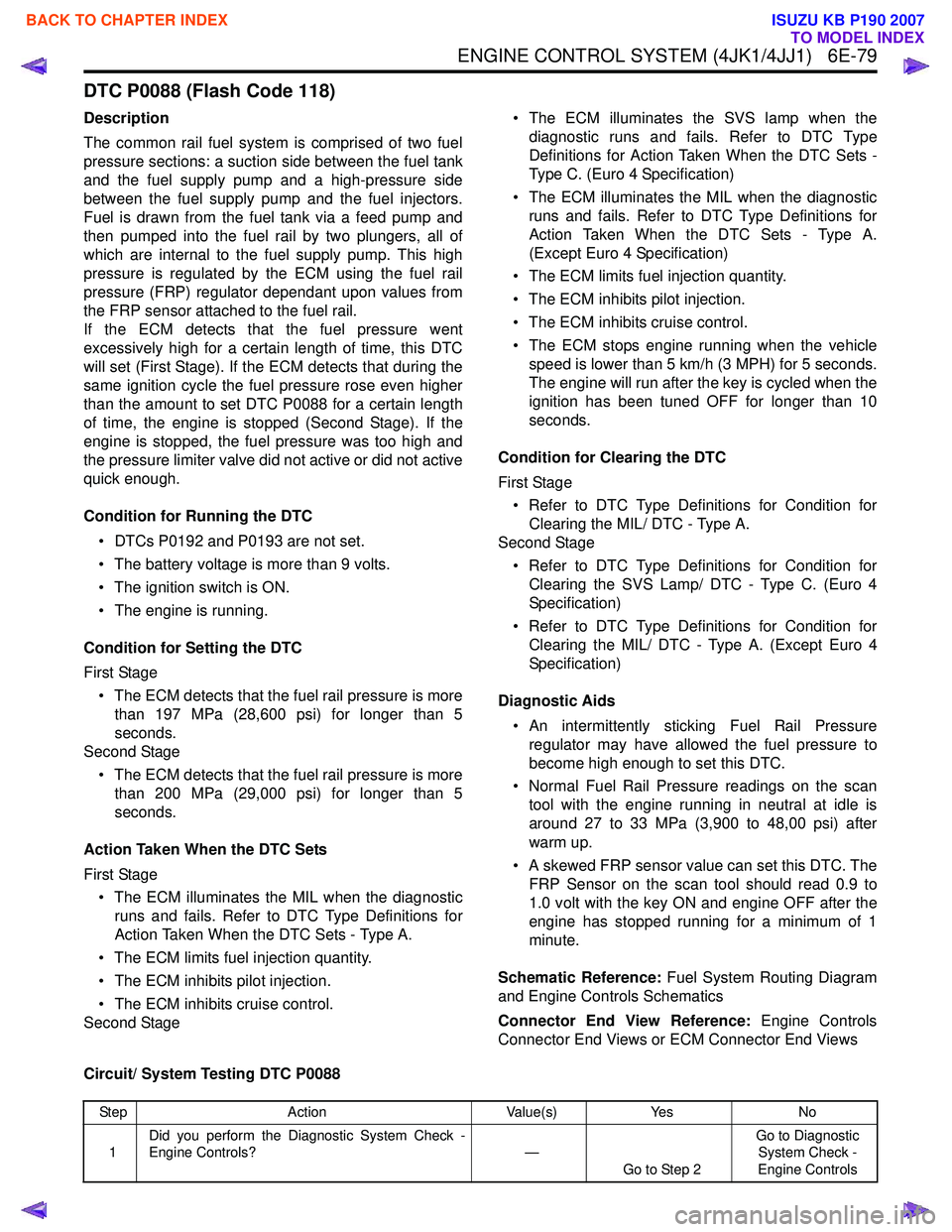
DTC P0088 (Flash Code 118)
Description
The common rail fuel system is comprised of two fuel
pressure sections: a suction side between the fuel tank
and the fuel supply pump and a high-pressure side
between the fuel supply pump and the fuel injectors.
Fuel is drawn from the fuel tank via a feed pump and
then pumped into the fuel rail by two plungers, all of
which are internal to the fuel supply pump. This high
pressure is regulated by the ECM using the fuel rail
pressure (FRP) regulator dependant upon values from
the FRP sensor attached to the fuel rail.
If the ECM detects that the fuel pressure went
excessively high for a certain length of time, this DTC
will set (First Stage). If the ECM detects that during the
same ignition cycle the fuel pressure rose even higher
than the amount to set DTC P0088 for a certain length
of time, the engine is stopped (Second Stage). If the
engine is stopped, the fuel pressure was too high and
the pressure limiter valve did not active or did not active
quick enough.
Condition for Running the DTC • DTCs P0192 and P0193 are not set.
• The battery voltage is more than 9 volts.
• The ignition switch is ON.
• The engine is running.
Condition for Setting the DTC
First Stage • The ECM detects that the fuel rail pressure is more than 197 MPa (28,600 psi) for longer than 5
seconds.
Second Stage
• The ECM detects that the fuel rail pressure is more than 200 MPa (29,000 psi) for longer than 5
seconds.
Action Taken When the DTC Sets
First Stage • The ECM illuminates the MIL when the diagnostic runs and fails. Refer to DTC Type Definitions for
Action Taken When the DTC Sets - Type A.
• The ECM limits fuel injection quantity.
• The ECM inhibits pilot injection.
• The ECM inhibits cruise control.
Second Stage • The ECM illuminates the SVS lamp when the
diagnostic runs and fails. Refer to DTC Type
Definitions for Action Taken When the DTC Sets -
Type C. (Euro 4 Specification)
• The ECM illuminates the MIL when the diagnostic runs and fails. Refer to DTC Type Definitions for
Action Taken When the DTC Sets - Type A.
(Except Euro 4 Specification)
• The ECM limits fuel injection quantity.
• The ECM inhibits pilot injection.
• The ECM inhibits cruise control.
• The ECM stops engine running when the vehicle speed is lower than 5 km/h (3 MPH) for 5 seconds.
The engine will run after the key is cycled when the
ignition has been tuned OFF for longer than 10
seconds.
Condition for Clearing the DTC
First Stage • Refer to DTC Type Definitions for Condition for Clearing the MIL/ DTC - Type A.
Second Stage
• Refer to DTC Type Definitions for Condition for Clearing the SVS Lamp/ DTC - Type C. (Euro 4
Specification)
• Refer to DTC Type Definitions for Condition for Clearing the MIL/ DTC - Type A. (Except Euro 4
Specification)
Diagnostic Aids • An intermittently sticking Fuel Rail Pressure regulator may have allowed the fuel pressure to
become high enough to set this DTC.
• Normal Fuel Rail Pressure readings on the scan tool with the engine running in neutral at idle is
around 27 to 33 MPa (3,900 to 48,00 psi) after
warm up.
• A skewed FRP sensor value can set this DTC. The FRP Sensor on the scan tool should read 0.9 to
1.0 volt with the key ON and engine OFF after the
engine has stopped running for a minimum of 1
minute.
Schematic Reference: Fuel System Routing Diagram
and Engine Controls Schematics
Connector End View Reference: Engine Controls
Connector End Views or ECM Connector End Views
Circuit/ System Testing DTC P0088
Step Action Value(s)Yes No
1 Did you perform the Diagnostic System Check -
Engine Controls? —
Go to Step 2 Go to Diagnostic
System Check -
Engine Controls
BACK TO CHAPTER INDEX
TO MODEL INDEX
ISUZU KB P190 2007
Page 1701 of 6020
6E-84 ENGINE CONTROL SYSTEM (4JK1/4JJ1)
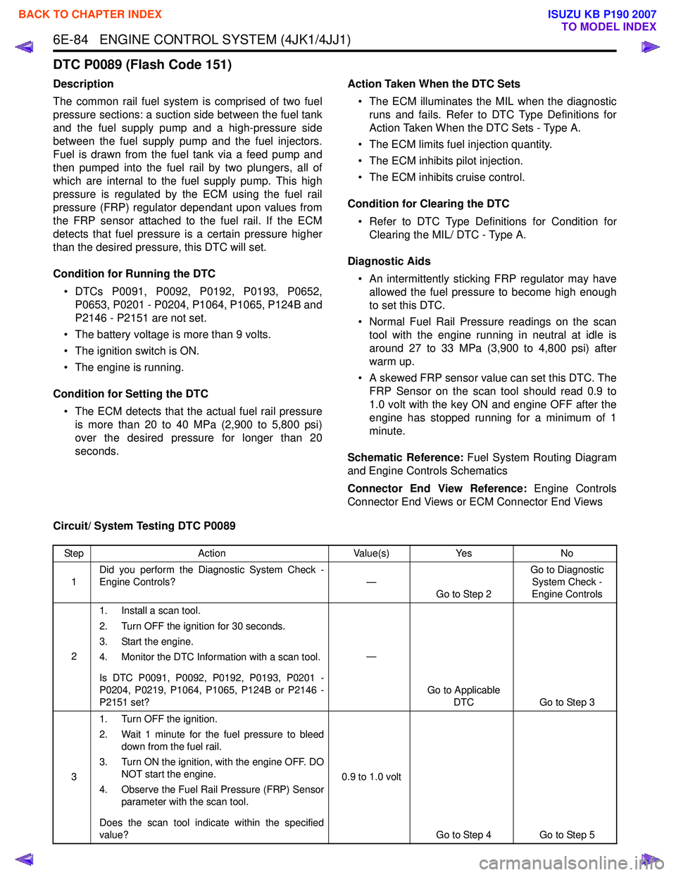
DTC P0089 (Flash Code 151)
Description
The common rail fuel system is comprised of two fuel
pressure sections: a suction side between the fuel tank
and the fuel supply pump and a high-pressure side
between the fuel supply pump and the fuel injectors.
Fuel is drawn from the fuel tank via a feed pump and
then pumped into the fuel rail by two plungers, all of
which are internal to the fuel supply pump. This high
pressure is regulated by the ECM using the fuel rail
pressure (FRP) regulator dependant upon values from
the FRP sensor attached to the fuel rail. If the ECM
detects that fuel pressure is a certain pressure higher
than the desired pressure, this DTC will set.
Condition for Running the DTC • DTCs P0091, P0092, P0192, P0193, P0652, P0653, P0201 - P0204, P1064, P1065, P124B and
P2146 - P2151 are not set.
• The battery voltage is more than 9 volts.
• The ignition switch is ON.
• The engine is running.
Condition for Setting the DTC • The ECM detects that the actual fuel rail pressure is more than 20 to 40 MPa (2,900 to 5,800 psi)
over the desired pressure for longer than 20
seconds. Action Taken When the DTC Sets
• The ECM illuminates the MIL when the diagnostic runs and fails. Refer to DTC Type Definitions for
Action Taken When the DTC Sets - Type A.
• The ECM limits fuel injection quantity.
• The ECM inhibits pilot injection.
• The ECM inhibits cruise control.
Condition for Clearing the DTC • Refer to DTC Type Definitions for Condition for Clearing the MIL/ DTC - Type A.
Diagnostic Aids • An intermittently sticking FRP regulator may have allowed the fuel pressure to become high enough
to set this DTC.
• Normal Fuel Rail Pressure readings on the scan tool with the engine running in neutral at idle is
around 27 to 33 MPa (3,900 to 4,800 psi) after
warm up.
• A skewed FRP sensor value can set this DTC. The FRP Sensor on the scan tool should read 0.9 to
1.0 volt with the key ON and engine OFF after the
engine has stopped running for a minimum of 1
minute.
Schematic Reference: Fuel System Routing Diagram
and Engine Controls Schematics
Connector End View Reference: Engine Controls
Connector End Views or ECM Connector End Views
Circuit/ System Testing DTC P0089
Step Action Value(s)Yes No
1 Did you perform the Diagnostic System Check -
Engine Controls? —
Go to Step 2 Go to Diagnostic
System Check -
Engine Controls
2 1. Install a scan tool.
2. Turn OFF the ignition for 30 seconds.
3. Start the engine.
4. Monitor the DTC Information with a scan tool.
Is DTC P0091, P0092, P0192, P0193, P0201 -
P0204, P0219, P1064, P1065, P124B or P2146 -
P2151 set? —
Go to Applicable DTC Go to Step 3
3 1. Turn OFF the ignition.
2. Wait 1 minute for the fuel pressure to bleed down from the fuel rail.
3. Turn ON the ignition, with the engine OFF. DO NOT start the engine.
4. Observe the Fuel Rail Pressure (FRP) Sensor parameter with the scan tool.
Does the scan tool indicate within the specified
value? 0.9 to 1.0 volt
Go to Step 4 Go to Step 5
BACK TO CHAPTER INDEX
TO MODEL INDEX
ISUZU KB P190 2007