2007 ISUZU KB P190 seat adjustment
[x] Cancel search: seat adjustmentPage 992 of 6020

6C – 28 FUEL SYSTEM
Injection Nozzle Adjustment
First nozzle opening pressure adjustment
1.Clamp the nozzle holder in a vise.
2. Install the shim, first spring and spring seat in the nozzle holder.
3. Install the collar, second spring, shim, spring seat and pushrod in the nozzle holder.
4. Install the pins, lift piece and spacer in the nozzle holder.
040MV015.tif
040MV016.tif
040MV017.tif
040MV018.tif
BACK TO CHAPTER INDEX
TO MODEL INDEX
ISUZU KB P190 2007
Page 1446 of 6020
6A-86 ENGINE MECHANICAL (4JK1/4JJ1)
014RY00027
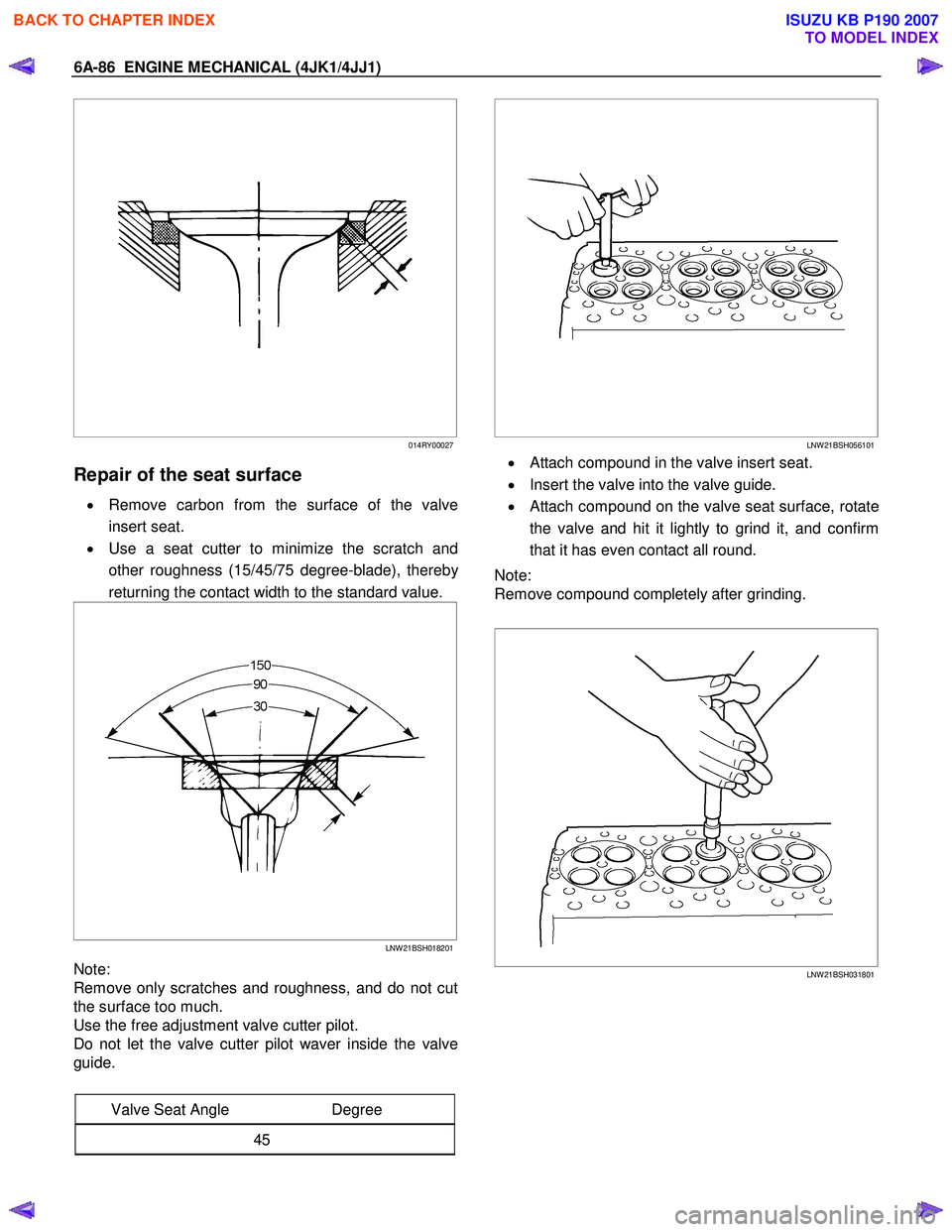
Repair of the seat surface
• Remove carbon from the surface of the valve
insert seat.
• Use a seat cutter to minimize the scratch and
other roughness (15/45/75 degree-blade), thereb
y
returning the contact width to the standard value.
LNW 21BSH018201
Note:
Remove only scratches and roughness, and do not cut
the surface too much.
Use the free adjustment valve cutter pilot.
Do not let the valve cutter pilot waver inside the valve
guide.
Valve Seat Angle Degree
45
LNW 21BSH056101
• Attach compound in the valve insert seat.
• Insert the valve into the valve guide.
•
Attach compound on the valve seat surface, rotate
the valve and hit it lightly to grind it, and confirm
that it has even contact all round.
Note:
Remove compound completely after grinding.
LNW 21BSH031801
BACK TO CHAPTER INDEX
TO MODEL INDEX
ISUZU KB P190 2007
Page 1538 of 6020
ENGINE COOLING (4JK1/4JJ1) 6B-15
Inspection and Repair
Make the necessary adjustments, repairs, and part
replacements if excessive wear or damage is
discovered during inspection.
Radiator Cap
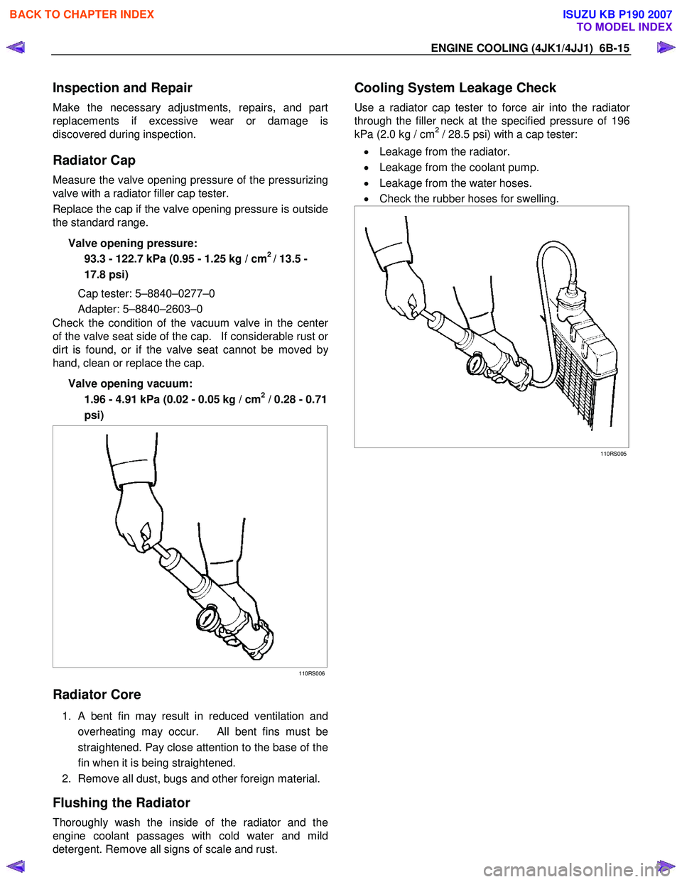
Measure the valve opening pressure of the pressurizing
valve with a radiator filler cap tester.
Replace the cap if the valve opening pressure is outside
the standard range.
Valve opening pressure: 93.3 - 122.7 kPa (0.95 - 1.25 kg / cm
2 / 13.5 -
17.8 psi)
Cap tester: 5–8840–0277–0
Adapter: 5–8840–2603–0
Check the condition of the vacuum valve in the cente
r
of the valve seat side of the cap. If considerable rust or
dirt is found, or if the valve seat cannot be moved by
hand, clean or replace the cap.
Valve opening vacuum: 1.96 - 4.91 kPa (0.02 - 0.05 kg / cm
2 / 0.28 - 0.71
psi)
110RS006
Radiator Core
1. A bent fin may result in reduced ventilation and
overheating may occur. All bent fins must be
straightened. Pay close attention to the base of the
fin when it is being straightened.
2. Remove all dust, bugs and other foreign material.
Flushing the Radiator
Thoroughly wash the inside of the radiator and the
engine coolant passages with cold water and mild
detergent. Remove all signs of scale and rust.
Cooling System Leakage Check
Use a radiator cap tester to force air into the radiator
through the filler neck at the specified pressure of 196
kPa (2.0 kg / cm2 / 28.5 psi) with a cap tester:
• Leakage from the radiator.
• Leakage from the coolant pump.
• Leakage from the water hoses.
• Check the rubber hoses for swelling.
110RS005
BACK TO CHAPTER INDEX
TO MODEL INDEX
ISUZU KB P190 2007
Page 2011 of 6020
ENGINE DIAGNOSIS (C24SE) 6-11
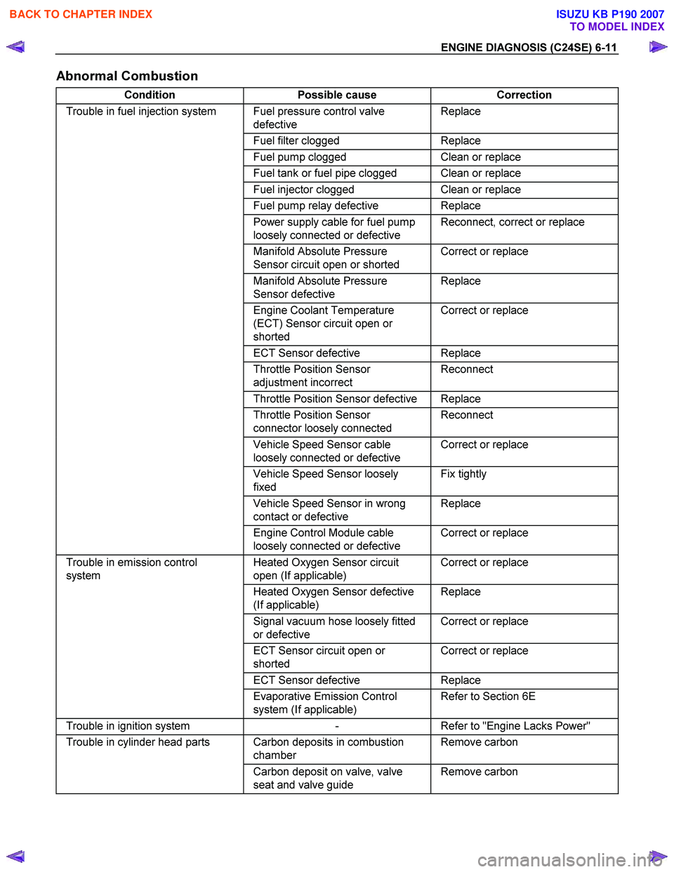
Abnormal Combustion
Condition Possible cause Correction
Trouble in fuel injection system Fuel pressure control valve
defective Replace
Fuel filter clogged Replace
Fuel pump clogged Clean or replace
Fuel tank or fuel pipe clogged Clean or replace
Fuel injector clogged Clean or replace
Fuel pump relay defective Replace
Power supply cable for fuel pump
loosely connected or defective Reconnect, correct or replace
Manifold Absolute Pressure
Sensor circuit open or shorted Correct or replace
Manifold Absolute Pressure
Sensor defective Replace
Engine Coolant Temperature
(ECT) Sensor circuit open or
shorted Correct or replace
ECT Sensor defective Replace
Throttle Position Sensor
adjustment incorrect Reconnect
Throttle Position Sensor defective Replace
Throttle Position Sensor
connector loosely connected Reconnect
Vehicle Speed Sensor cable
loosely connected or defective Correct or replace
Vehicle Speed Sensor loosely
fixed Fix tightly
Vehicle Speed Sensor in wrong
contact or defective Replace
Engine Control Module cable
loosely connected or defective Correct or replace
Trouble in emission control
system Heated Oxygen Sensor circuit
open (If applicable) Correct or replace
Heated Oxygen Sensor defective
(If applicable) Replace
Signal vacuum hose loosely fitted
or defective Correct or replace
ECT Sensor circuit open or
shorted Correct or replace
ECT Sensor defective Replace
Evaporative Emission Control
system (If applicable) Refer to Section 6E
Trouble in ignition system
- Refer to "Engine Lacks Power"
Trouble in cylinder head parts Carbon deposits in combustion
chamber Remove carbon
Carbon deposit on valve, valve
seat and valve guide Remove carbon
BACK TO CHAPTER INDEX
TO MODEL INDEX
ISUZU KB P190 2007
Page 2027 of 6020

ENGINE MECHANICAL (C24SE) 6A-13
Valve System C24SE
Actuation Type Direct-acting Inverted Bucked Tappet
Valve Clearance Adjustment Hydraulic
Valve Rotor Type None
Inlet-Valve Material Chromium Alloyed Steel
-Seat Insert MaterialSintered Iron
Exhaust-Valve Material Head: Cr-Mn-Ni Alloyed Shaft: Cr-Si Alloyed &Cr plated
-Seat Insert MaterialSintered Iron
Valve Spring Material GME 06 100-C1
Valve Guide Material QS 13 MR 00
Valve Seal Type Lip
Water Pump C24SE
Type Centrifugal
Drive-Material &Type HNBR Toothed-belt
Bearing Type Double Row Ball
Shaft Seal Type Mechanical Ceramic
Thermostat-Coolant C24SE
Type Bypass
Oil Pump & Filter C24SE
Type Gear Pump
Location Front of Engine
Drive Direct Crankshaft Driven
Filter Type Full Flow with Bypass for blocked filter
Oil & Oil Reservoir C24SE
Reservoir-Description & Location 1-piece below Engine
Reservoir Material Aluminum Alloy (pressure cast)
Replacement Oil Fill Volume
-W ith Filter change4.25liters
-W ithout Filter change 4.00liters
Recommended Oil-Run-in 10W /30SG
-Service (above-18°C) 10W /40SG
-Service (below-18°C) 5W /30SG
Oil Classification API&CCMC
Ignition Components C24SE
Spark Plugs Conventional
Type Electronic Spark Control
No. of Coils &Type 2 Solid State
Coil Location Engine-mounted
Ignition Lead Type Inductive (hi-resistance)
BACK TO CHAPTER INDEX
TO MODEL INDEX
ISUZU KB P190 2007
Page 2093 of 6020
ENGINE MECHANICAL (C24SE) 6A-79
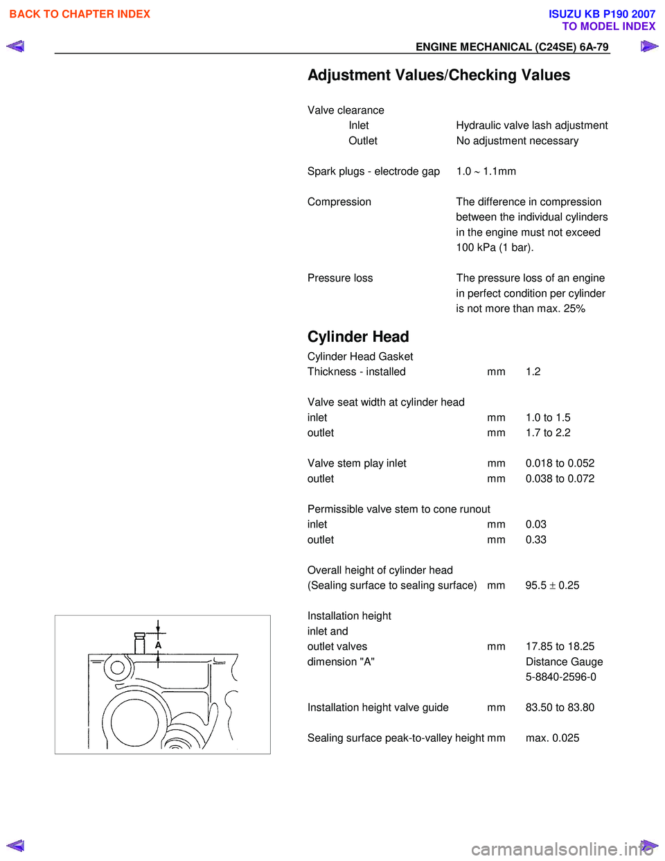
Adjustment Values/Checking Values
Valve clearance Inlet Hydraulic valve lash adjustment
Outlet No adjustment necessary
Spark plugs - electrode gap 1.0 ∼ 1.1mm
Compression The difference in compression
between the individual cylinders
in the engine must not exceed
100 kPa (1 bar).
Pressure loss The pressure loss of an engine
in perfect condition per cylinder
is not more than max. 25%
Cylinder Head
Cylinder Head Gasket
Thickness - installed mm 1.2
Valve seat width at cylinder head
inlet mm 1.0 to 1.5
outlet mm 1.7 to 2.2
Valve stem play inlet mm 0.018 to 0.052
outlet mm 0.038 to 0.072
Permissible valve stem to cone runout
inlet mm 0.03
outlet mm 0.33
Overall height of cylinder head
(Sealing surface to sealing surface) mm 95.5 ± 0.25
Installation height
inlet and
outlet valves mm 17.85 to 18.25
dimension "A" Distance Gauge
5-8840-2596-0
Installation height valve guide mm 83.50 to 83.80
Sealing surface peak-to-valley height mm max. 0.025
BACK TO CHAPTER INDEX
TO MODEL INDEX
ISUZU KB P190 2007
Page 2225 of 6020
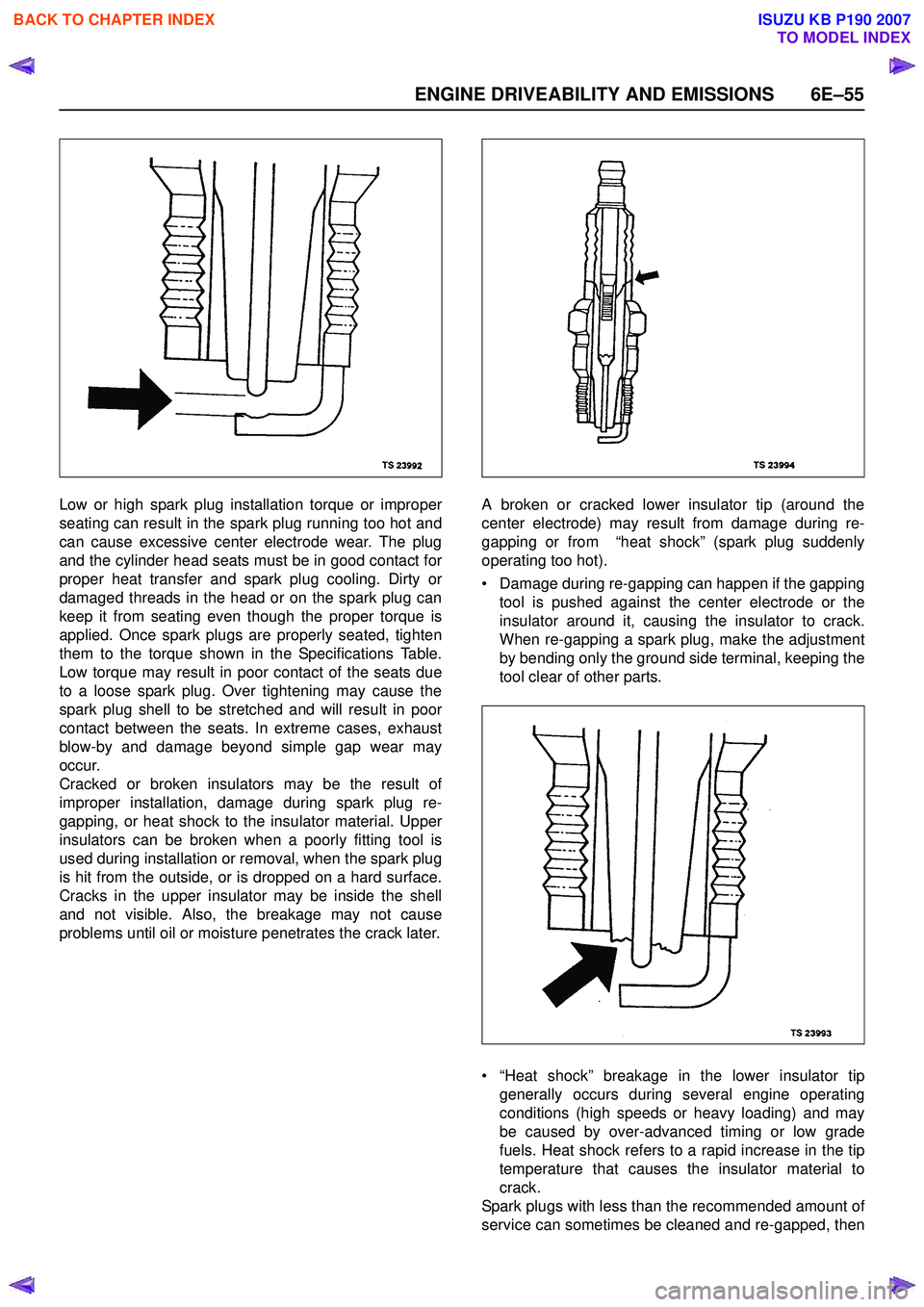
ENGINE DRIVEABILITY AND EMISSIONS 6E–55
Low or high spark plug installation torque or improper
seating can result in the spark plug running too hot and
can cause excessive center electrode wear. The plug
and the cylinder head seats must be in good contact for
proper heat transfer and spark plug cooling. Dirty or
damaged threads in the head or on the spark plug can
keep it from seating even though the proper torque is
applied. Once spark plugs are properly seated, tighten
them to the torque shown in the Specifications Table.
Low torque may result in poor contact of the seats due
to a loose spark plug. Over tightening may cause the
spark plug shell to be stretched and will result in poor
contact between the seats. In extreme cases, exhaust
blow-by and damage beyond simple gap wear may
occur.
Cracked or broken insulators may be the result of
improper installation, damage during spark plug re-
gapping, or heat shock to the insulator material. Upper
insulators can be broken when a poorly fitting tool is
used during installation or removal, when the spark plug
is hit from the outside, or is dropped on a hard surface.
Cracks in the upper insulator may be inside the shell
and not visible. Also, the breakage may not cause
problems until oil or moisture penetrates the crack later. A broken or cracked lower insulator tip (around the
center electrode) may result from damage during re-
gapping or from “heat shock” (spark plug suddenly
operating too hot).
• Damage during re-gapping can happen if the gapping tool is pushed against the center electrode or the
insulator around it, causing the insulator to crack.
When re-gapping a spark plug, make the adjustment
by bending only the ground side terminal, keeping the
tool clear of other parts.
• “Heat shock” breakage in the lower insulator tip generally occurs during several engine operating
conditions (high speeds or heavy loading) and may
be caused by over-advanced timing or low grade
fuels. Heat shock refers to a rapid increase in the tip
temperature that causes the insulator material to
crack.
Spark plugs with less than the recommended amount of
service can sometimes be cleaned and re-gapped, then
BACK TO CHAPTER INDEX
TO MODEL INDEX
ISUZU KB P190 2007
Page 5115 of 6020
ELECTRICAL-BODY AND CHASSIS 8A-177
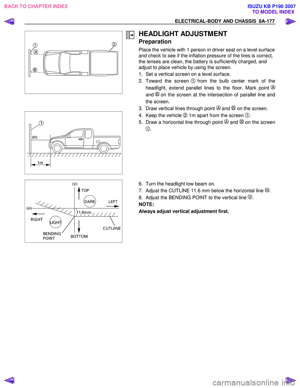
HEADLIGHT ADJUSTMENT
Preparation
Place the vehicle with 1 person in driver seat on a level surface
and check to see if the inflation pressure of the tires is correct,
the lenses are clean, the battery is sufficiently charged, and
adjust to place vehicle by using the screen.
1. Set a vertical screen on a level surface.
2. Toward the screen
1from the bulb center mark of the
headlight, extend parallel lines to the floor. Mark point
A
and B on the screen at the intersection of parallel line and
the screen.
3. Draw vertical lines through point
A and B on the screen.
4. Keep the vehicle 2 1m apart from the screen 1.
5. Draw a horizontal line through point
A and Bon the screen
1.
6. Turn the headlight low beam on.
7. Adjust the CUTLINE 11.6 mm below the horizontal line
H.
8. Adjust the BENDING POINT to the vertical line
V.
NOTE:
Always adjust vertical adjustment first.
BACK TO CHAPTER INDEX TO MODEL INDEXISUZU KB P190 2007