2007 ISUZU KB P190 radio
[x] Cancel search: radioPage 3691 of 6020
Powertrain Interface Module – V6 Page 6E1–30
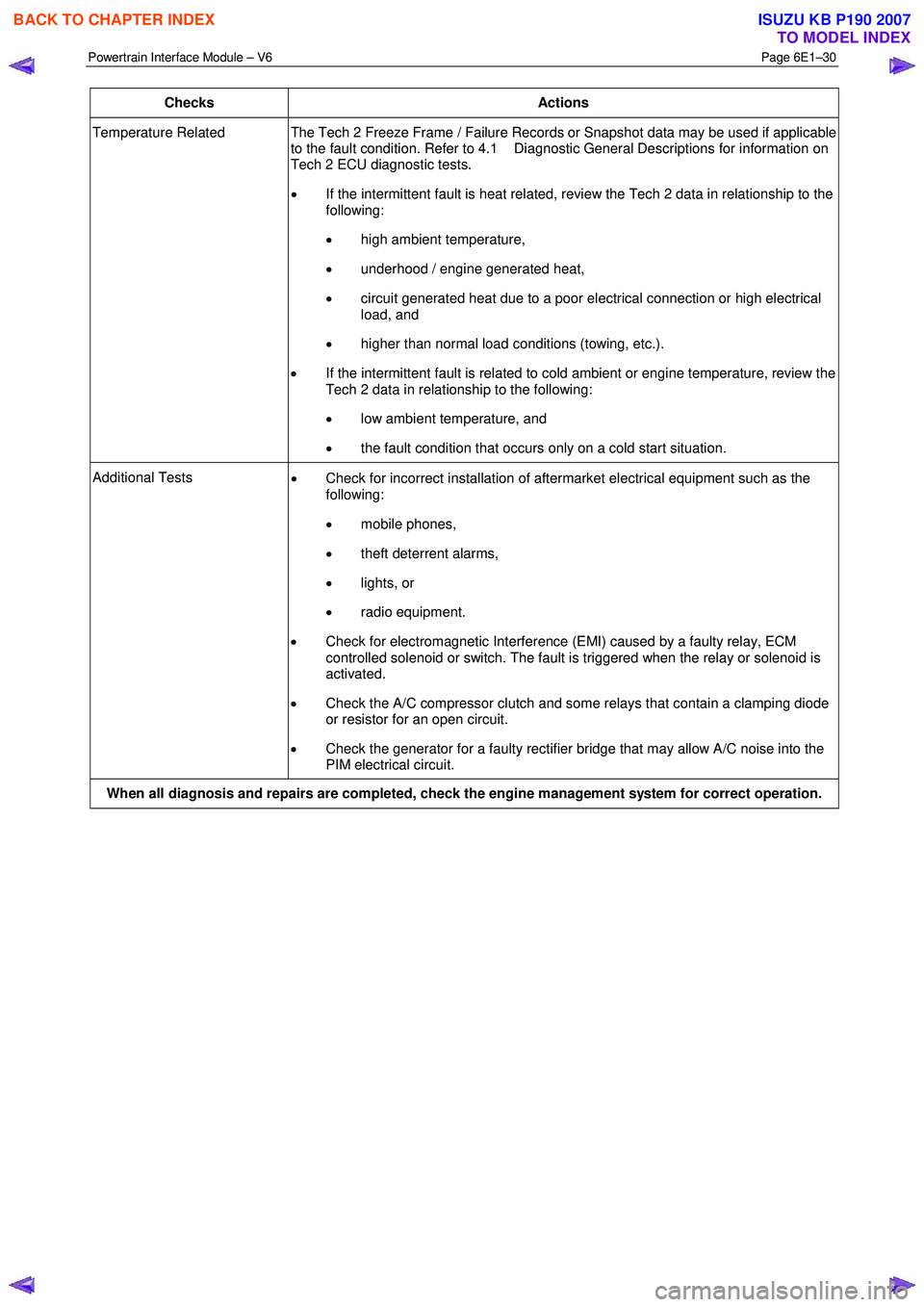
Checks Actions
Temperature Related The Tech 2 Freeze Frame / Failure Records or Snapshot data may be used if applicable
to the fault condition. Refer to 4.1 Diagnostic General Descriptions for information on
Tech 2 ECU diagnostic tests.
• If the intermittent fault is heat related, review the Tech 2 data in relationship to the
following:
• high ambient temperature,
• underhood / engine generated heat,
• circuit generated heat due to a poor electrical connection or high electrical
load, and
• higher than normal load conditions (towing, etc.).
• If the intermittent fault is related to cold ambient or engine temperature, review the
Tech 2 data in relationship to the following:
• low ambient temperature, and
• the fault condition that occurs only on a cold start situation.
Additional Tests
• Check for incorrect installation of aftermarket electrical equipment such as the
following:
• mobile phones,
• theft deterrent alarms,
• lights, or
• radio equipment.
• Check for electromagnetic Interference (EMI) caused by a faulty relay, ECM
controlled solenoid or switch. The fault is triggered when the relay or solenoid is
activated.
• Check the A/C compressor clutch and some relays that contain a clamping diode
or resistor for an open circuit.
• Check the generator for a faulty rectifier bridge that may allow A/C noise into the
PIM electrical circuit.
When all diagnosis and repairs are completed, check the engine management system for correct operation.
BACK TO CHAPTER INDEX
TO MODEL INDEX
ISUZU KB P190 2007
Page 4378 of 6020
7A2-94 TRANSMISSION CONTROL SYSTEM (JR405E)
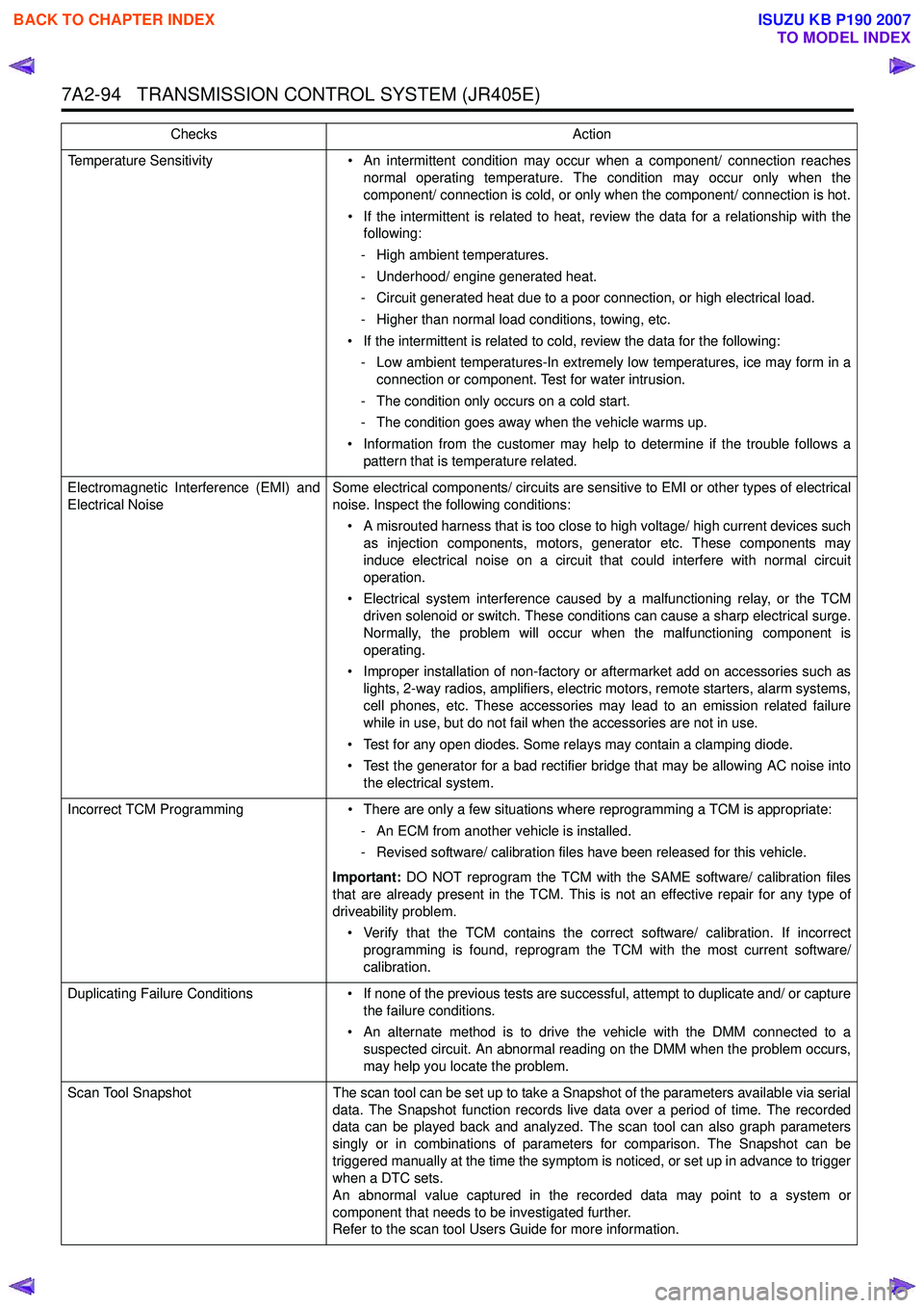
Temperature Sensitivity• An intermittent condition may occur when a component/ connection reaches
normal operating temperature. The condition may occur only when the
component/ connection is cold, or only when the component/ connection is hot.
• If the intermittent is related to heat, review the data for a relationship with the following:
- High ambient temperatures.
- Underhood/ engine generated heat.
- Circuit generated heat due to a poor connection, or high electrical load.
- Higher than normal load conditions, towing, etc.
• If the intermittent is related to cold, review the data for the following: - Low ambient temperatures-In extremely low temperatures, ice may form in a connection or component. Test for water intrusion.
- The condition only occurs on a cold start.
- The condition goes away when the vehicle warms up.
• Information from the customer may help to determine if the trouble follows a pattern that is temperature related.
Electromagnetic Interference (EMI) and
Electrical Noise Some electrical components/ circuits are sensitive to EMI or other types of electrical
noise. Inspect the following conditions:
• A misrouted harness that is too close to high voltage/ high current devices such as injection components, motors, generator etc. These components may
induce electrical noise on a circuit that could interfere with normal circuit
operation.
• Electrical system interference caused by a malfunctioning relay, or the TCM driven solenoid or switch. These conditions can cause a sharp electrical surge.
Normally, the problem will occur when the malfunctioning component is
operating.
• Improper installation of non-factory or aftermarket add on accessories such as lights, 2-way radios, amplifiers, electric motors, remote starters, alarm systems,
cell phones, etc. These accessories may lead to an emission related failure
while in use, but do not fail when the accessories are not in use.
• Test for any open diodes. Some relays may contain a clamping diode.
• Test the generator for a bad rectifier bridge that may be allowing AC noise into the electrical system.
Incorrect TCM Programming • There are only a few situations where reprogramming a TCM is appropriate:
- An ECM from another vehicle is installed.
- Revised software/ calibration files have been released for this vehicle.
Important: DO NOT reprogram the TCM with the SAME software/ calibration files
that are already present in the TCM. This is not an effective repair for any type of
driveability problem.
• Verify that the TCM contains the correct software/ calibration. If incorrect programming is found, reprogram the TCM with the most current software/
calibration.
Duplicating Failure Conditions • If none of the previous tests are successful, attempt to duplicate and/ or capture
the failure conditions.
• An alternate method is to drive the vehicle with the DMM connected to a suspected circuit. An abnormal reading on the DMM when the problem occurs,
may help you locate the problem.
Scan Tool Snapshot The scan tool can be set up to take a Snapshot of the parameters available via serial
data. The Snapshot function records live data over a period of time. The recorded
data can be played back and analyzed. The scan tool can also graph parameters
singly or in combinations of parameters for comparison. The Snapshot can be
triggered manually at the time the symptom is noticed, or set up in advance to trigger
when a DTC sets.
An abnormal value captured in the recorded data may point to a system or
component that needs to be investigated further.
Refer to the scan tool Users Guide for more information.
Checks
Action
BACK TO CHAPTER INDEX
TO MODEL INDEX
ISUZU KB P190 2007
Page 5887 of 6020
11A-36 IMMOBILIZER CONTROL SYSTEM (4JK1/4JJ1/HFV6)
Resetting and Programming
Resetting and Programming Guidelines
Notice:The security information must be programmed
when the ICU, ECM, PIM or transponder key(s) is
replaced, or transponder key(s) is added.
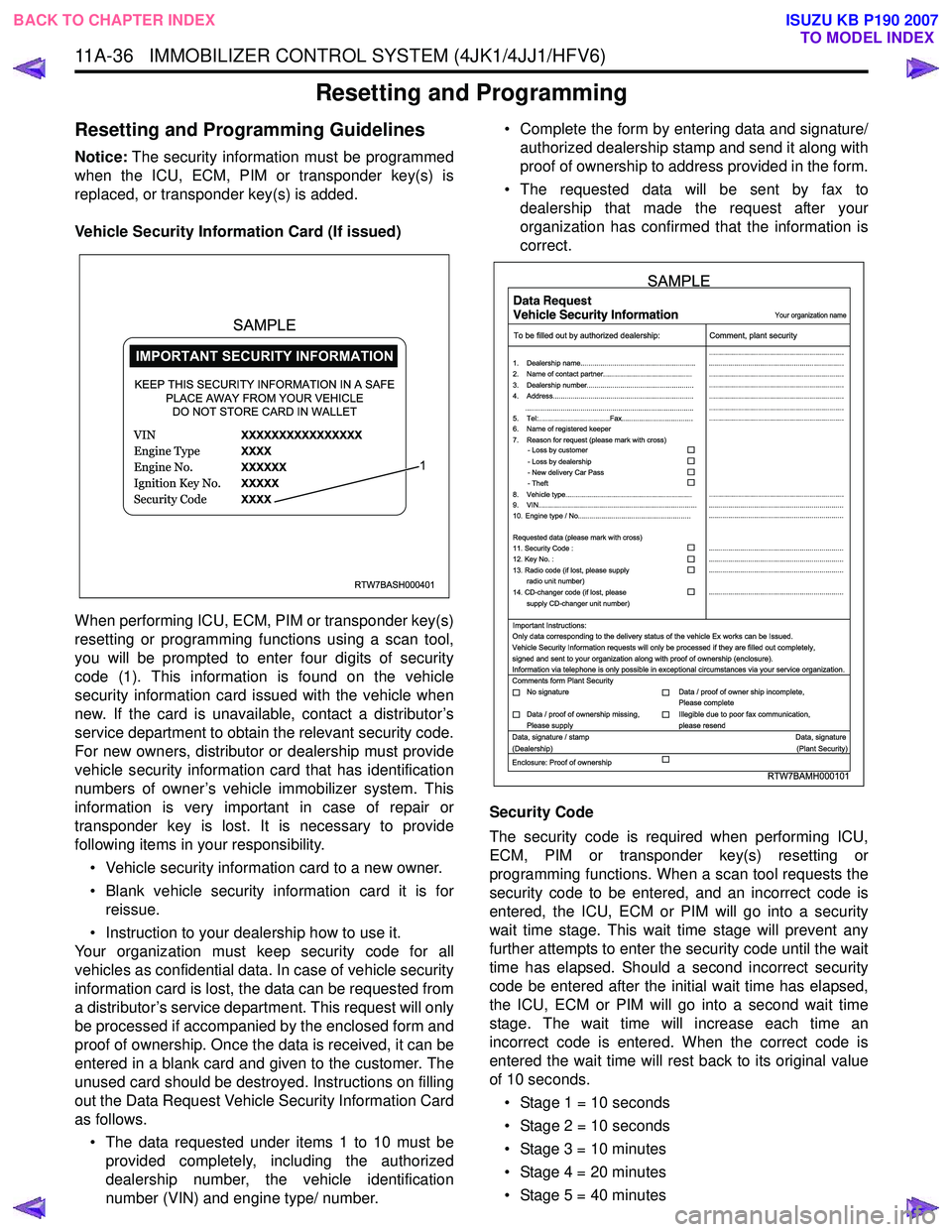
Vehicle Security Information Card (If issued)
When performing ICU, ECM, PIM or transponder key(s)
resetting or programming functions using a scan tool,
you will be prompted to enter four digits of security
code (1). This information is found on the vehicle
security information card issued with the vehicle when
new. If the card is unavailable, contact a distributor’s
service department to obtain the relevant security code.
For new owners, distributor or dealership must provide
vehicle security information card that has identification
numbers of owner’s vehicle immobilizer system. This
information is very important in case of repair or
transponder key is lost. It is necessary to provide
following items in your responsibility.
• Vehicle security information card to a new owner.
• Blank vehicle security information card it is for reissue.
• Instruction to your dealership how to use it.
Your organization must keep security code for all
vehicles as confidential data. In case of vehicle security
information card is lost, the data can be requested from
a distributor’s service department. This request will only
be processed if accompanied by the enclosed form and
proof of ownership. Once the data is received, it can be
entered in a blank card and given to the customer. The
unused card should be destroyed. Instructions on filling
out the Data Request Vehicle Security Information Card
as follows.
• The data requested under items 1 to 10 must be provided completely, including the authorized
dealership number, the vehicle identification
number (VIN) and engine type/ number. • Complete the form by entering data and signature/
authorized dealership stamp and send it along with
proof of ownership to address provided in the form.
• The requested data will be sent by fax to dealership that made the request after your
organization has confirmed that the information is
correct.
Security Code
The security code is required when performing ICU,
ECM, PIM or transponder key(s) resetting or
programming functions. When a scan tool requests the
security code to be entered, and an incorrect code is
entered, the ICU, ECM or PIM will go into a security
wait time stage. This wait time stage will prevent any
further attempts to enter the security code until the wait
time has elapsed. Should a second incorrect security
code be entered after the initial wait time has elapsed,
the ICU, ECM or PIM will go into a second wait time
stage. The wait time will increase each time an
incorrect code is entered. When the correct code is
entered the wait time will rest back to its original value
of 10 seconds.
• Stage 1 = 10 seconds
• Stage 2 = 10 seconds
• Stage 3 = 10 minutes
• Stage 4 = 20 minutes
• Stage 5 = 40 minutes
RTW7BASH000401
KEEP THIS SECURITY INFORMATION IN A SAFE PLACE AWAY FROM YOUR VEHICLEDO NOT STORE CARD IN WALLET
1
SAMPLE
RTW7BAMH000101
Your organization name
To be filled out by authorized dealership: Comment, plant security
1. Dealership name.......................................................... ....................................................................
....................................................................
....................................................................
....................................................................
....................................................................
....................................................................
....................................................................
....................................................................
.................................................................... ....................................................................
....................................................................
....................................................................
....................................................................
....................................................................
2. Name of contact partner.............................................
6. Name of registered keeper
7. Reason for request (please mark with cross)
3. Dealership number......................................................
4. Address.......................................................................
8. Vehicle type................................................................
9. VIN................................................................................
10. Engine type / No.........................................................
11. Security Code :
12. Key No. :
13. Radio code (if lost, please supply radio unit number)
14. CD-changer code (if lost, please
supply CD-changer unit number)
Requested data (please mark with cross)
5. Tel:....................................Fax....................................
.....................................................................................
- Loss by customer
- Loss by dealership
- New delivery Car Pass
- Theft
Important Instructions:
Comments form Plant Security
Data, signature / stamp Data, signature
(Dealership) (Plant Security)
Enclosure: Proof of ownership Only data corresponding to the delivery status of the vehicle Ex works can be Issued.
Vehicle Security Information requests will only be processed if they are filled out completely,
signed and sent to your organization along with proof of ownership (enclosure).
Information via telephone is only possible in exceptional circumstances via your service organization.
No signature Data / proof of owner ship incomplete,
Please complete
Data / proof of ownership missing,
Please supply Illegible due to poor fax communication,
please resend
SAMPLE
BACK TO CHAPTER INDEX TO MODEL INDEX
ISUZU KB P190 2007
Page 5897 of 6020
11A-46 IMMOBILIZER CONTROL SYSTEM (4JK1/4JJ1/HFV6)
The ICU is installed to the steering lock. The ICU
controls the immobilizer system by authentication of the
transponder key and the ECM. An antenna coil is a part
of the ICU and it is located around steering key lock
cylinder. An antenna coil is energized when the ICU is
performing an authentication of the transponder key.
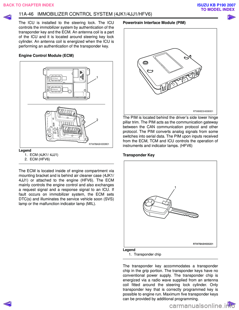
Engine Control Module (ECM)
Legend 1. ECM (4JK1/ 4JJ1)
2. ECM (HFV6)
The ECM is located inside of engine compartment via
mounting bracket and is behind air cleaner case (4JK1/
4JJ1) or attached to the engine (HFV6). The ECM
mainly controls the engine control and also exchanges
a request signal and a response signal to an ICU. If
fault occurs on immobilizer system, the ECM sets
DTC(s) and illuminates the service vehicle soon (SVS)
lamp or the malfunction indicator lamp (MIL). Powertrain Interface Module (PIM)
The PIM is located behind the driver’s side lower hinge
pillar trim. The PIM acts as the communication gateway
between the CAN communication protocol and other
protocol. The PIM converts analog signals from some
switches into serial data. The PIM upon inputs received
from the ECM, TCM and ICU controls the operation of
instruments and indicator lamps. (HFV6)
Transponder Key
Legend 1. Transponder chip
The transponder key accommodates a transponder
chip in the grip portion. The transponder keys have no
conventional power supply. The transponder chip is
energized via a radio wave supplied from an antenna
coil fitted around the steering lock cylinder. Only
transponder key that is correctly programmed key is
possible to engine run. Maximum five transponder keys
can be provided by additional programming.
RTW7BASH000201
1
BACK TO CHAPTER INDEX TO MODEL INDEX
ISUZU KB P190 2007
Page 5957 of 6020
ANTITHEFT SYSTEM 11B-3
Function of a keyless entry system
W ith a keyless entry system the car can be locked or
unlocked from any position around the car up to a
specified distance, by using the potable radio remote
transmitter inside key (remote key).
Status LED
W hile the system is in delay the alarm system is active
and LED flashes at 0.5Hz with or without activated
interior protection.
Hazard relay
The hazard warning lights will be activated by an
external relay. The output is low active.
Switches
All switches to ground. This makes it possible for failure
analysis to detect a short circuit or a broken wire to
each switch. To use this feature it is necessary to place
a 1.8k Ω resistor in parallel to the required switch.
Receiver
The receiver is integrated into the control unit.
To lower the idle current the receiver is equipped with a
standby mode. The antenna is integrated on the printed
circuit board.
Depending on the mounting position of the control unit
the antenna can be connected externally.
Range of communication
The range of communication between remote key and
receiver is intended to be least 3 m from centre of the
car.
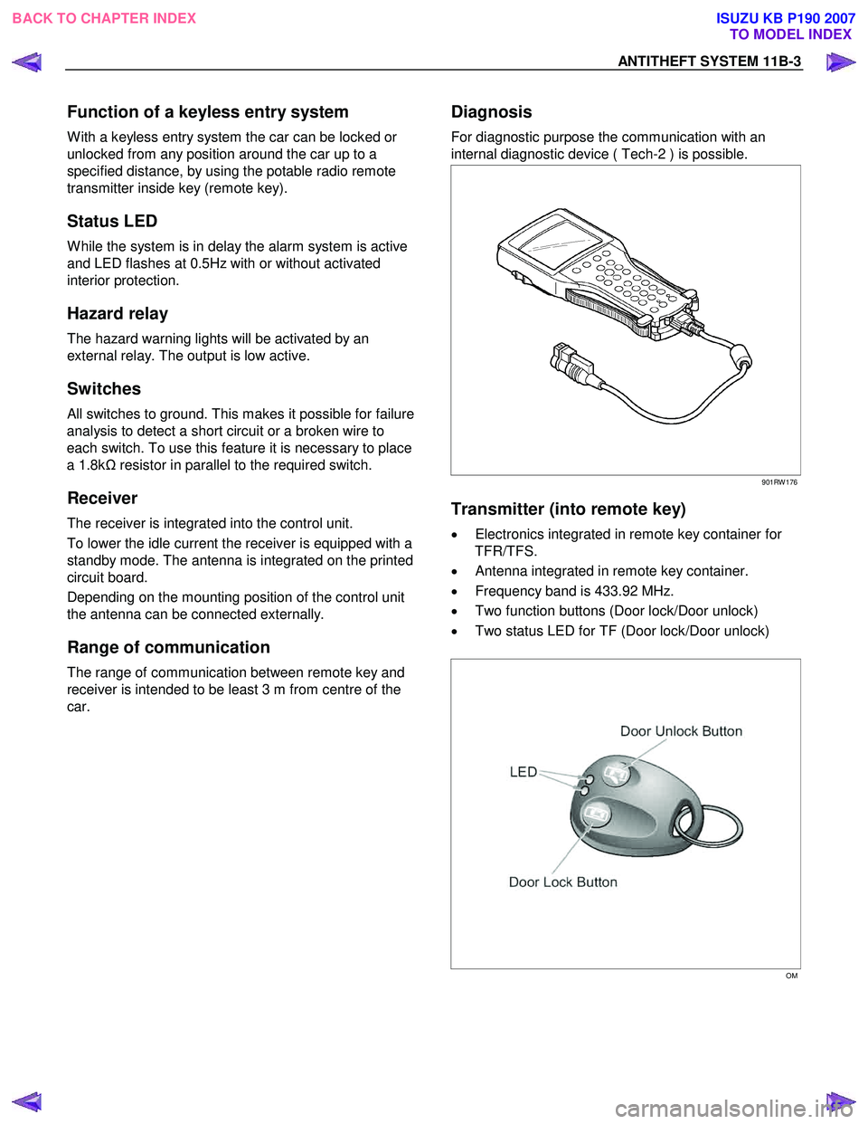
Diagnosis
For diagnostic purpose the communication with an
internal diagnostic device ( Tech-2 ) is possible.
901RW 176
Transmitter (into remote key)
• Electronics integrated in remote key container for
TFR/TFS.
• Antenna integrated in remote key container.
• Frequency band is 433.92 MHz.
• Two function buttons (Door lock/Door unlock)
• Two status LED for TF (Door lock/Door unlock)
OM
BACK TO CHAPTER INDEX TO MODEL INDEX
ISUZU KB P190 2007