2007 ISUZU KB P190 manual transmission
[x] Cancel search: manual transmissionPage 775 of 6020

PARKING BRAKE SYSTEM 5D-5
Front Parking Brake Cable
Front Parking Brake Cable and Associated Parts (Bench Seat)
RTW 75DMF000301
Legend
(1) Shift Knob (manual transmission)
(2) Front Floor Console
(3) Bolt
(4) Seat Assembly
(5) Buckle: side seat and Center Seat Belt
(6) Seat Adjuster
BACK TO CHAPTER INDEX
TO MODEL INDEX
ISUZU KB P190 2007
Page 1096 of 6020
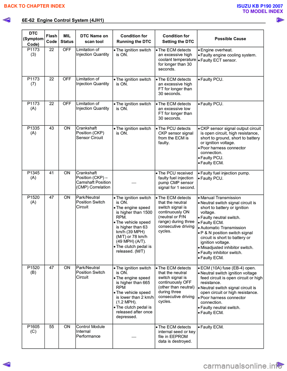
6E-62 Engine Control System (4JH1)
DTC
(Symptom Code) Flash
Code MIL
Status DTC Name on
scan tool Condition for
Running the DTC Condition for
Setting the DTC Possible Cause
P1173
(3) 22 OFF Limitation of
Injection Quantity •
The ignition switch
is ON. •
The ECM detects
an excessive high
coolant temperature
for longer than 30
seconds.
•
Engine overheat.
• Faulty engine cooling system.
• Faulty ECT sensor.
P1173 (7) 22 OFF Limitation of
Injection Quantity
•
The ignition switch
is ON. •
The ECM detects
an excessive high
FT for longer than
30 seconds.
•
Faulty PCU.
P1173 (A) 22 OFF Limitation of
Injection Quantity
•
The ignition switch
is ON. •
The ECM detects
an excessive low
FT for longer than
30 seconds.
•
Faulty PCU.
P1335 (A) 43 ON Crankshaft
Position (CKP)
Sensor Circuit •
The ignition switch
is ON. •
The PCU detects
CKP sensor signal
from the ECM is
faulty.
•
CKP sensor signal output circuit
is open circuit, high resistance,
short to ground, short to battery
or ignition voltage.
• Poor harness connector
connection.
• Faulty PCU.
• Faulty ECM.
P1345 (A) 41 ON Crankshaft
Position (CKP) –
Camshaft Position
(CMP) Correlation
•
The PCU received
faulty fuel injection
pump CMP sensor
signal for 1 second.
•
Faulty fuel injection pump.
• Faulty PCU.
P1520 (A) 47 ON Park/Neutral
Position Switch
Circuit •
The ignition switch
is ON.
• The engine speed
is higher than 1500
RPM.
• The vehicle speed
is higher than 63
km/h (39 MPH)
(M/T) or 78 km/h
(49 MPH) (A/T).
• The clutch pedal is
released. (M/T)
•
The ECM detects
that the neutral
switch signal is
continuously ON
(neutral or P/N
range) during three
consecutive driving
cycles.
•
Manual Transmission
• Neutral switch signal circuit is
short to battery or ignition
voltage.
• Faulty neutral switch.
• Faulty ECM.
• Automatic Transmission
• P & N position switch signal
circuit is short to battery or
ignition voltage.
• Misadjusted inhibitor switch.
• Faulty inhibitor switch.
• Faulty ECM.
P1520 (B) 47 ON Park/Neutral
Position Switch
Circuit •
The ignition switch
is ON.
• The engine speed
is higher than 665
RPM
• The vehicle speed
is lower than 2 km/h
(1.2 MPH).
• The clutch pedal is
released after once
depressed.
•
The ECM detects
that the neutral
switch signal is
continuously OFF
(other than neutral)
during three
consecutive driving
cycles.
•
ECM (10A) fuse (EB-4) open.
• Neutral switch ignition voltage
feed circuit is open circuit or high
resistance.
• Neutral switch signal circuit is
open circuit or high resistance.
• Poor harness connector
connection.
• Faulty neutral switch.
• Faulty ECM.
P1605 (C) 55 ON Control Module
Internal
Performance •
The ECM detects
internal seed or key
file in EEPROM
data is destroyed.
•
Faulty ECM.
BACK TO CHAPTER INDEX
TO MODEL INDEX
ISUZU KB P190 2007
Page 1168 of 6020
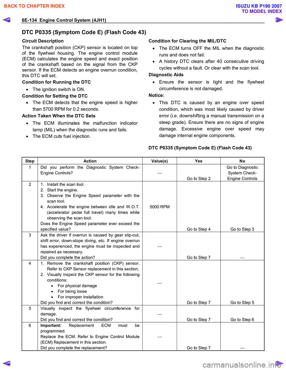
6E-134 Engine Control System (4JH1)
DTC P0335 (Symptom Code E) (Flash Code 43)
Circuit Description
The crankshaft position (CKP) sensor is located on top
of the flywheel housing. The engine control module
(ECM) calculates the engine speed and exact position
of the crankshaft based on the signal from the CKP
sensor. If the ECM detects an engine overrun condition,
this DTC will set.
Condition for Running the DTC
• The ignition switch is ON.
Condition for Setting the DTC • The ECM detects that the engine speed is highe
r
than 5700 RPM for 0.2 seconds.
Action Taken When the DTC Sets
• The ECM illuminates the malfunction indicato
r
lamp (MIL) when the diagnostic runs and fails.
• The ECM cuts fuel injection.
Condition for Clearing the MIL/DTC
• The ECM turns OFF the MIL when the diagnostic
runs and does not fail.
• A history DTC clears after 40 consecutive driving
cycles without a fault. Or clear with the scan tool.
Diagnostic Aids
• Ensure the sensor is tight and the flywheel
circumference is not damaged.
Notice:
• This DTC is caused by an engine over speed
condition, which was most likely caused by drive
r
error (i.e. downshifting a manual transmission on a
steep grade). Ensure there are no signs of engine
damage. Excessive engine over speed ma
y
damage internal engine components.
DTC P0335 (Symptom Code E) (Flash Code 43)
Step Action Value(s) Yes No
1 Did you perform the Diagnostic System Check-
Engine Controls?
Go to Step 2 Go to Diagnostic
System Check-
Engine Controls
2 1. Install the scan tool. 2. Start the engine.
3. Observe the Engine Speed parameter with the scan tool.
4. Accelerate the engine between idle and W .O.T. (accelerator pedal full travel) many times while
observing the scan tool.
Does the Engine Speed parameter ever exceed the
specified value? 5000 RPM
Go to Step 4 Go to Step 3
3 Ask the driver if overrun is caused by gear slip-out, shift error, down-slope diving, etc. If engine overrun
has experienced, the engine must be inspected and
repaired as necessary.
Did you complete the action?
Go to Step 7
4 1. Remove the crankshaft position (CKP) sensor.
Refer to CKP Sensor replacement in this section.
2. Visually inspect the CKP sensor for the following conditions: • For physical damage
• For being loose
• For improper installation
Did you find and correct the condition?
Go to Step 7 Go to Step 5
5 Visually inspect the flywheel circumference for damage.
Did you find and correct the condition?
Go to Step 7 Go to Step 6
6 Important: Replacement ECM must be
programmed.
Replace the ECM. Refer to Engine Control Module
(ECM) Replacement in this section.
Did you complete the replacement?
Go to Step 7
BACK TO CHAPTER INDEX
TO MODEL INDEX
ISUZU KB P190 2007
Page 1244 of 6020
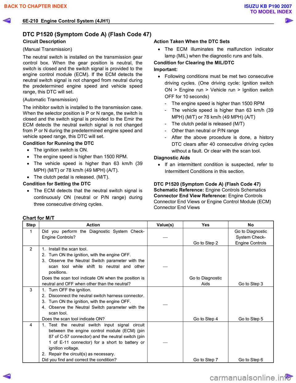
6E-210 Engine Control System (4JH1)
DTC P1520 (Symptom Code A) (Flash Code 47)
Circuit Description
(Manual Transmission)
The neutral switch is installed on the transmission gea
r
control box. W hen the gear position is neutral, the
switch is closed and the switch signal is provided to the
engine control module (ECM). If the ECM detects the
neutral switch signal is not changed from neutral during
the predetermined engine speed and vehicle speed
range, this DTC will set.
(Automatic Transmission)
The inhibitor switch is installed to the transmission case.
W hen the selector position is P or N range, the switch is
closed and the switch signal is provided to the Emir the
ECM detects the neutral switch signal is not changed
from P or N during the predetermined engine speed and
vehicle speed range, this DTC will set.
Condition for Running the DTC • The ignition switch is ON.
• The engine speed is higher than 1500 RPM.
• The vehicle speed is higher than 63 km/h (39
MPH) (M/T) or 78 km/h (49 MPH) (A/T).
• The clutch pedal is released. (M/T).
Condition for Setting the DTC
• The ECM detects that the neutral switch signal is
continuously ON (neutral or P/N range) during
three consecutive driving cycles.
Action Taken When the DTC Sets
• The ECM illuminates the malfunction indicato
r
lamp (MIL) when the diagnostic runs and fails.
Condition for Clearing the MIL/DTC
Important: • Following conditions must be met two consecutive
driving cycles. (One driving cycle: Ignition switch
ON > Engine run > Vehicle run > Ignition switch
OFF for 10 seconds)
- The engine speed is higher than 1500 RPM
- The vehicle speed is higher than 63 km/h (39 MPH) (M/T) or 78 km/h (49 MPH) (A/T)
- The clutch pedal is released (M/T)
- Other than neutral or P/N range
- After the above procedure is done, a history
DTC clears after 40 consecutive driving cycles
without a fault. Or clear with the scan tool.
Diagnostic Aids
• If an intermittent condition is suspected, refer to
Intermittent Conditions in this section.
DTC P1520 (Symptom Code A) (Flash Code 47)
Schematic Reference: Engine Controls Schematics
Connector End View Reference: Engine Controls
Connector End Views or Engine Control Module (ECM)
Connector End Views
Chart for M/T
Step Action Value(s) Yes No
1 Did you perform the Diagnostic System Check-
Engine Controls?
Go to Step 2 Go to Diagnostic
System Check-
Engine Controls
2 1. Install the scan tool. 2. Turn ON the ignition, with the engine OFF.
3. Observe the Neutral Switch parameter with the scan tool while shift to neutral and other
positions.
Does the scan tool indicate ON when the position is
neutral and OFF when other than the neutral?
Go to Diagnostic Aids Go to Step 3
3 1. Turn OFF the ignition. 2. Disconnect the neutral switch harness connector.
3. Turn ON the ignition, with the engine OFF.
4. Observe the Neutral Switch parameter with the scan tool.
Does the scan tool indicate ON?
Go to Step 4 Go to Step 5
4 1. Test the neutral switch input signal circuit between the engine control module (ECM) (pin
87 of C-57 connector) and the neutral switch (pin
1 of E-11 connector) for a short to battery or
ignition voltage.
2. Repair the circuit(s) as necessary.
Did you find and correct the condition?
Go to Step 7 Go to Step 6
BACK TO CHAPTER INDEX
TO MODEL INDEX
ISUZU KB P190 2007
Page 1247 of 6020
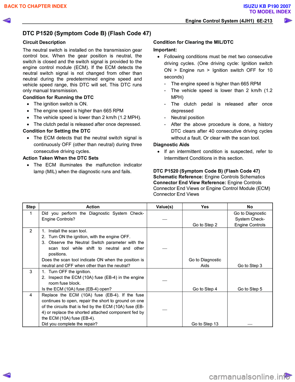
Engine Control System (4JH1) 6E-213
DTC P1520 (Symptom Code B) (Flash Code 47)
Circuit Description
The neutral switch is installed on the transmission gea
r
control box. W hen the gear position is neutral, the
switch is closed and the switch signal is provided to the
engine control module (ECM). If the ECM detects the
neutral switch signal is not changed from other than
neutral during the predetermined engine speed and
vehicle speed range, this DTC will set. This DTC runs
only manual transmission.
Condition for Running the DTC
• The ignition switch is ON.
• The engine speed is higher than 665 RPM
• The vehicle speed is lower than 2 km/h (1.2 MPH).
• The clutch pedal is released after once depressed.
Condition for Setting the DTC • The ECM detects that the neutral switch signal is
continuously OFF (other than neutral) during three
consecutive driving cycles.
Action Taken When the DTC Sets • The ECM illuminates the malfunction indicato
r
lamp (MIL) when the diagnostic runs and fails.
Condition for Clearing the MIL/DTC
Important: • Following conditions must be met two consecutive
driving cycles. (One driving cycle: Ignition switch
ON > Engine run > Ignition switch OFF for 10
seconds)
- The engine speed is higher than 665 RPM
- The vehicle speed is lower than 2 km/h (1.2 MPH)
- The clutch pedal is released after once depressed
- Neutral position
- After the above procedure is done, a history
DTC clears after 40 consecutive driving cycles
without a fault. Or clear with the scan tool.
Diagnostic Aids
• If an intermittent condition is suspected, refer to
Intermittent Conditions in this section.
DTC P1520 (Symptom Code B) (Flash Code 47)
Schematic Reference: Engine Controls Schematics
Connector End View Reference: Engine Controls
Connector End Views or Engine Control Module (ECM)
Connector End Views
Step Action Value(s) Yes No
1 Did you perform the Diagnostic System Check-
Engine Controls?
Go to Step 2 Go to Diagnostic
System Check-
Engine Controls
2 1. Install the scan tool. 2. Turn ON the ignition, with the engine OFF.
3. Observe the Neutral Switch parameter with the scan tool while shift to neutral and other
positions.
Does the scan tool indicate ON when the position is
neutral and OFF when other than the neutral?
Go to Diagnostic Aids Go to Step 3
3 1. Turn OFF the ignition. 2. Inspect the ECM (10A) fuse (EB-4) in the engine room fuse block.
Is the ECM (10A) fuse (EB-4) open?
Go to Step 4 Go to Step 5
4 Replace the ECM (10A) fuse (EB-4). If the fuse continues to open, repair the short to ground on one
of the circuits that is fed by the ECM (10A) fuse (EB-
4) or replace the shorted attached component fed by
the ECM (10A) fuse (EB-4).
Did you complete the repair?
Go to Step 13
BACK TO CHAPTER INDEX
TO MODEL INDEX
ISUZU KB P190 2007
Page 1305 of 6020
Engine Control System (4JH1) 6E-271
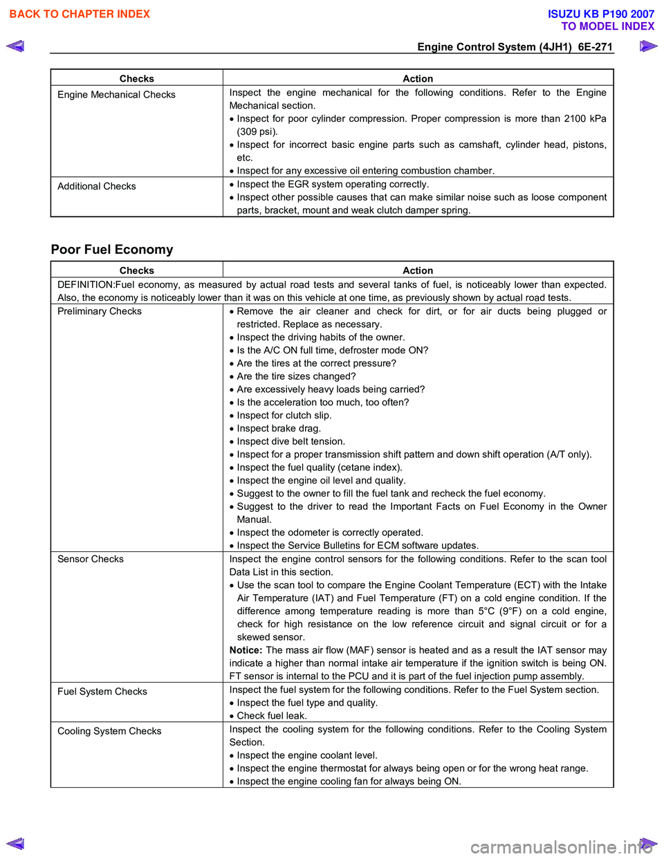
Checks Action
Engine Mechanical Checks Inspect the engine mechanical for the following conditions. Refer to the Engine
Mechanical section.
• Inspect for poor cylinder compression. Proper compression is more than 2100 kPa
(309 psi).
• Inspect for incorrect basic engine parts such as camshaft, cylinder head, pistons,
etc.
• Inspect for any excessive oil entering combustion chamber.
Additional Checks •
Inspect the EGR system operating correctly.
• Inspect other possible causes that can make similar noise such as loose component
parts, bracket, mount and weak clutch damper spring.
Poor Fuel Economy
Checks Action
DEFINITION:Fuel economy, as measured by actual road tests and several tanks of fuel, is noticeably lower than expected.
Also, the economy is noticeably lower than it was on this vehicle at one time, as previously shown by actual road tests.
Preliminary Checks • Remove the air cleaner and check for dirt, or for air ducts being plugged or
restricted. Replace as necessary.
• Inspect the driving habits of the owner.
• Is the A/C ON full time, defroster mode ON?
• Are the tires at the correct pressure?
• Are the tire sizes changed?
• Are excessively heavy loads being carried?
• Is the acceleration too much, too often?
• Inspect for clutch slip.
• Inspect brake drag.
• Inspect dive belt tension.
• Inspect for a proper transmission shift pattern and down shift operation (A/T only).
• Inspect the fuel quality (cetane index).
• Inspect the engine oil level and quality.
• Suggest to the owner to fill the fuel tank and recheck the fuel economy.
• Suggest to the driver to read the Important Facts on Fuel Economy in the Owner
Manual.
• Inspect the odometer is correctly operated.
• Inspect the Service Bulletins for ECM software updates.
Sensor Checks Inspect the engine control sensors for the following conditions. Refer to the scan tool
Data List in this section.
• Use the scan tool to compare the Engine Coolant Temperature (ECT) with the Intake
Air Temperature (IAT) and Fuel Temperature (FT) on a cold engine condition. If the
difference among temperature reading is more than 5°C (9°F) on a cold engine,
check for high resistance on the low reference circuit and signal circuit or for a
skewed sensor.
Notice: The mass air flow (MAF) sensor is heated and as a result the IAT sensor may
indicate a higher than normal intake air temperature if the ignition switch is being ON.
FT sensor is internal to the PCU and it is part of the fuel injection pump assembly.
Fuel System Checks Inspect the fuel system for the following conditions. Refer to the Fuel System section.
• Inspect the fuel type and quality.
• Check fuel leak.
Cooling System Checks Inspect the cooling system for the following conditions. Refer to the Cooling System
Section.
• Inspect the engine coolant level.
• Inspect the engine thermostat for always being open or for the wrong heat range.
• Inspect the engine cooling fan for always being ON.
BACK TO CHAPTER INDEX
TO MODEL INDEX
ISUZU KB P190 2007
Page 1375 of 6020
ENGINE MECHANICAL (4JK1/4JJ1) 6A-15
Engine Assembly
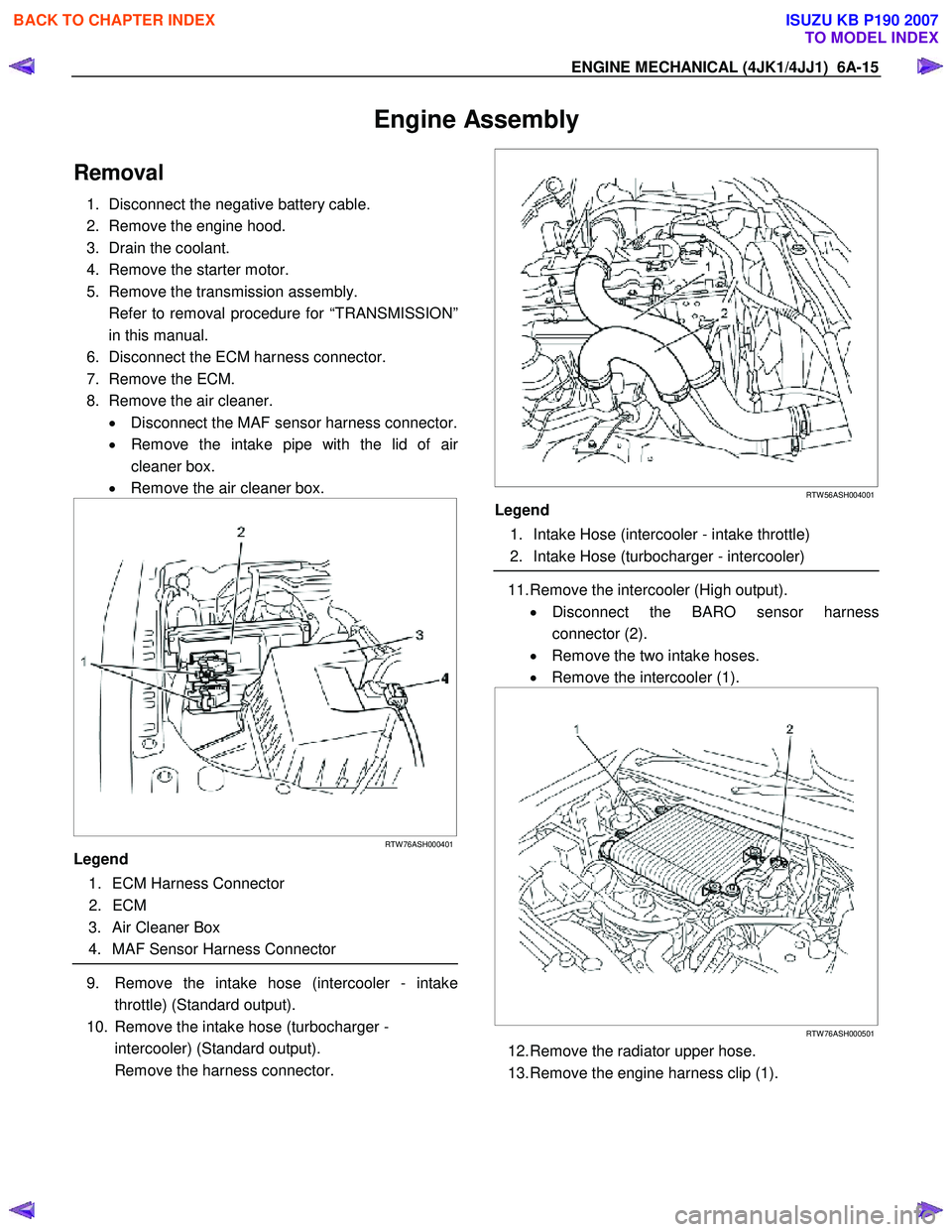
Removal
1. Disconnect the negative battery cable.
2. Remove the engine hood.
3. Drain the coolant.
4. Remove the starter motor.
5. Remove the transmission assembly.
Refer to removal procedure for “TRANSMISSION” in this manual.
6. Disconnect the ECM harness connector.
7. Remove the ECM.
8. Remove the air cleaner. • Disconnect the MAF sensor harness connector.
• Remove the intake pipe with the lid of ai
r
cleaner box.
• Remove the air cleaner box.
RTW 76ASH000401
Legend
1. ECM Harness Connector
2. ECM
3. Air Cleaner Box
4. MAF Sensor Harness Connector
9. Remove the intake hose (intercooler - intake
throttle) (Standard output).
10. Remove the intake hose (turbocharger - intercooler) (Standard output).
Remove the harness connector.
RTW 56ASH004001
Legend
1. Intake Hose (intercooler - intake throttle)
2. Intake Hose (turbocharger - intercooler)
11. Remove the intercooler (High output).
• Disconnect the BARO sensor harness
connector (2).
• Remove the two intake hoses.
• Remove the intercooler (1).
RTW 76ASH000501
12. Remove the radiator upper hose.
13. Remove the engine harness clip (1).
BACK TO CHAPTER INDEX
TO MODEL INDEX
ISUZU KB P190 2007
Page 1377 of 6020
ENGINE MECHANICAL (4JK1/4JJ1) 6A-17
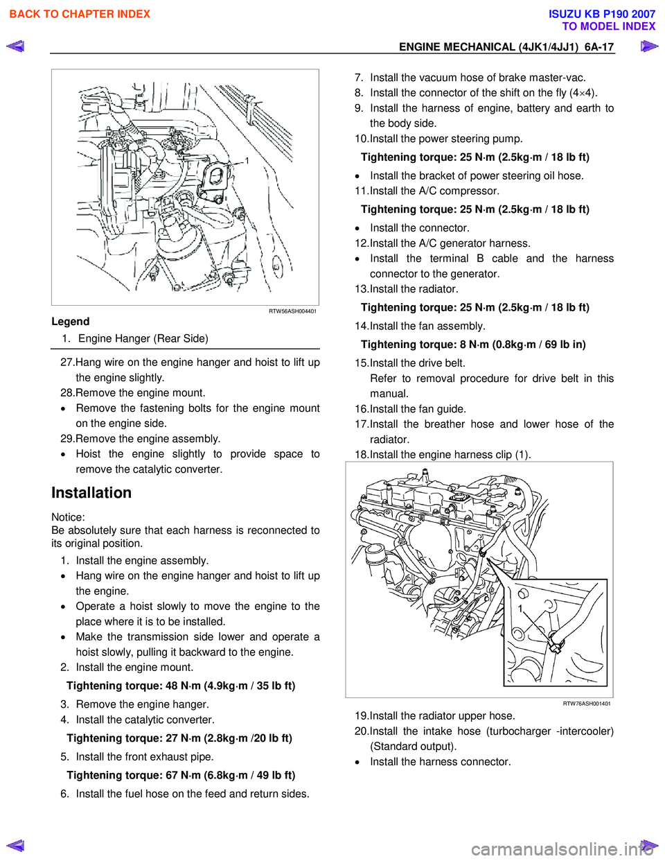
RTW 56ASH004401
Legend
1. Engine Hanger (Rear Side)
27.Hang wire on the engine hanger and hoist to lift up
the engine slightly.
28.Remove the engine mount.
• Remove the fastening bolts for the engine mount
on the engine side.
29.Remove the engine assembly.
• Hoist the engine slightly to provide space to
remove the catalytic converter.
Installation
Notice:
Be absolutely sure that each harness is reconnected to
its original position.
1. Install the engine assembly.
• Hang wire on the engine hanger and hoist to lift up
the engine.
• Operate a hoist slowly to move the engine to the
place where it is to be installed.
• Make the transmission side lower and operate a
hoist slowly, pulling it backward to the engine.
2. Install the engine mount.
Tightening torque: 48 N ⋅
⋅⋅
⋅
m (4.9kg ⋅
⋅⋅
⋅
m / 35 lb ft)
3. Remove the engine hanger.
4. Install the catalytic converter.
Tightening torque: 27 N ⋅
⋅⋅
⋅
m (2.8kg ⋅
⋅⋅
⋅
m /20 lb ft)
5. Install the front exhaust pipe. Tightening torque: 67 N ⋅
⋅⋅
⋅
m (6.8kg ⋅
⋅⋅
⋅
m / 49 lb ft)
6. Install the fuel hose on the feed and return sides.
7. Install the vacuum hose of brake master-vac.
8. Install the connector of the shift on the fly (4 ×4).
9. Install the harness of engine, battery and earth to the body side.
10.Install the power steering pump.
Tightening torque: 25 N ⋅
⋅⋅
⋅
m (2.5kg ⋅
⋅⋅
⋅
m / 18 lb ft)
• Install the bracket of power steering oil hose.
11.Install the A/C compressor.
Tightening torque: 25 N ⋅
⋅⋅
⋅
m (2.5kg ⋅
⋅⋅
⋅
m / 18 lb ft)
• Install the connector.
12.Install the A/C generator harness.
• Install the terminal B cable and the harness
connector to the generator.
13.Install the radiator.
Tightening torque: 25 N ⋅
⋅⋅
⋅
m (2.5kg ⋅
⋅⋅
⋅
m / 18 lb ft)
14.Install the fan assembly. Tightening torque: 8 N ⋅
⋅⋅
⋅
m (0.8kg ⋅
⋅⋅
⋅
m / 69 lb in)
15.Install the drive belt.
Refer to removal procedure for drive belt in this manual.
16.Install the fan guide.
17.Install the breather hose and lower hose of the radiator.
18.Install the engine harness clip (1).
RTW 76ASH001401
19.Install the radiator upper hose.
20.Install the intake hose (turbocharger -intercooler) (Standard output).
• Install the harness connector.
BACK TO CHAPTER INDEX
TO MODEL INDEX
ISUZU KB P190 2007