2007 ISUZU KB P190 gas type
[x] Cancel search: gas typePage 510 of 6020
4C1-6 FRONT WHEEL DRIVE
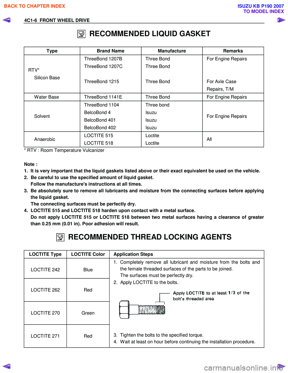
RECOMMENDED LIQUID GASKET
Type Brand Name Manufacture Remarks
RTV* Silicon Base ThreeBond 1207B
ThreeBond 1207C
ThreeBond 1215
Three Bond
Three Bond
Three Bond
For Engine Repairs
For Axle Case
Repairs, T/M
W ater Base ThreeBond 1141E Three Bond For Engine Repairs
Solvent ThreeBond 1104
BelcoBond 4
BelcoBond 401
BelcoBond 402 Three bond
Isuzu
Isuzu
Isuzu
For Engine Repairs
Anaerobic LOCTITE 515
LOCTITE 518 Loctite
Loctite All
* RTV : Room Temperature Vulcanizer
Note :
1. It is very important that the liquid gaskets listed above or their exact equivalent be used on the vehicle.
2. Be careful to use the specified amount of liquid gasket. Follow the manufacture's instructions at all times.
3. Be absolutely sure to remove all lubricants and moisture from the connecting surfaces before applying the liquid gasket.
The connecting surfaces must be perfectly dry.
4. LOCTITE 515 and LOCTITE 518 harden upon contact with a metal surface.
Do not apply LOCTITE 515 or LOCTITE 518 between two metal surfaces having a clearance of greater than 0.25 mm (0.01 in). Poor adhesion will result.
RECOMMENDED THREAD LOCKING AGENTS
LOCTITE Type LOCTITE Color Application Steps
LOCTITE 242
Blue 1. Completely remove all lubricant and moisture from the bolts and
the female threaded surfaces of the parts to be joined.
The surfaces must be perfectly dry.
LOCTITE 262
Red 2. Apply LOCTITE to the bolts.
LOCTITE 270
Green
LOCTITE 271
Red
3. Tighten the bolts to the specified torque.
4. W ait at least on hour before continuing the installation procedure.
BACK TO CHAPTER INDEX
TO MODEL INDEX
ISUZU KB P190 2007
Page 827 of 6020

6A – 22 ENGINE MECHANICAL
RECOMMENDED LIQUID GASKET
Type Brand Name Manufacturer Remarks
RTV*
Silicon Base ThreeBond 1207B
ThreeBond 1207C Three Bond
Three Bond
W ater Base
ThreeBond 1141E
ThreeBond 1215 Three Bond
Three Bond
Solvent
ThreeBond 1104
Belco Bond 4
Belco Bond 401
Belco Bond 402 Three Bond
Isuzu
Isuzu
Isuzu
Anaerobic
LOCTITE 515
LOCTITE 518
LOCTITE 262 Loctite
Loctite
Loctite Recommended for
transaxle repairs
* RTV : Room Temperature Vulcanizer
Note:
1. It is very important that the liquid gaskets listed above or their exact equivalent be used on the vehicle.
2. Be careful to use the specified amount of liquid gasket. Follow the manufacturer’s instructions at all times.
3. Be absolutely sure to remove all lubricants and moisture from the connecting surfaces before applying the liquid gasket.
The connecting surfaces must be perfectly dry.
4. LOCTITE 515 and LOCTITE 518 harden upon contact with a metal surface. Do not apply LOCTITE 515 or LOCTITE 518 between two metal surfaces having a clearance of
greater than 0.25 mm (0.01 in). Poor adhesion will result.
BACK TO CHAPTER INDEX
TO MODEL INDEX
ISUZU KB P190 2007
Page 841 of 6020

6A – 36 ENGINE MECHANICAL
GENERAL DESCRIPTION
RTW 46AMF000401
The 4J series automotive diesel engine has special designed combustion chambers in the piston. This design
provides superior fuel economy over a wide range of driving conditions.
Auto-thermatic pistons with cast steel struts are used to reduce thermal expansion and resulting engine noise when
the engine is cold.
Chrome plated dry type cylinder liners provide the highest durability.
The laminated steel sheet cylinder head gasket is very durable and, to increase the head gasket reliability.
The crankshaft has been tufftrided to provide a longer service life. Because the crankshaft is tufftrided, it cannot be
reground.
The 4JA1T(L) engine is equipped with the BOSCH VE-Type distributor injection pump.
The 4JH1TC and 4JA1TC engine is equipped with the BOSCH VP44-Type distributor injection pump.
The engine is turbocharger equipped.
BACK TO CHAPTER INDEX
TO MODEL INDEX
ISUZU KB P190 2007
Page 893 of 6020

6A – 88 ENGINE MECHANICAL
4. Visually inspect the piston rings.
If a piston ring groove is damaged or distorted, the piston
must be replaced.
Piston Pin Diameter
Use a micrometer to measure the piston pin diameter at
several points.
If the measured value is less than the specified limit, the piston
pin must be replaced.
Piston Pin Diameter mm
(in)
Standard Limit
30.995-31.000
(1.2202-1.2204) 30.97
(1.2193)
Piston Pin and Piston Clearance
Use and inside dial indicator to measure the piston pin hole (in
the piston).
Piston Pin Hole mm
(in)
4JA1T (L) 31.002-31.010 (1.2206-1.2208)
4JA1TC, 4JH1TC 31.005-31.013 (1.2207-1.2210)
Piston Pin and Piston Pin Hole Clearance mm (in)
4JA1T (L) 0.002-0.015 (0.00008-0.0006)
4JA1TC, 4JH1TC 0.005-0.018 (0.0002-0.0007)
CYLINDER HEAD GASKET SELECTION
Cylinder head gasket is determined by the piston head
projection from the cylinder body upper surface, in order to
improve engine performance.
Three types of gasket are provided by the difference of
thickness. Select the adequet one out of three grades of
gasket, according to the following procedure.
Before measurement, clear off carbon from the piston head
and cylinder body surface and also clean the place where a
gasket was installed.
015LX026
015RW048
011LX011
BACK TO CHAPTER INDEX
TO MODEL INDEX
ISUZU KB P190 2007
Page 955 of 6020

ENGINE COOLING 6B – 11
Inspection and Repair
The water pump is not disassembled type.
Make necessary parts replacement if extreme wear or
damage is found during inspection. Should any of the
following problems occur, the entire water pump assembly
must be replaced.
・ Cracks in the water pump body
・ Coolant leakage from the seal unit
・ Excessive radial play or abnormal noise in the fan center
when rotate by hand
・ Excessive thrust play in the fan center (Standard play: less
than 0.2mm)
・ Cracks or corrosion in the impeller
Installation
1. Water Pump
1) Install the water pump with new gasket.
2) Tighten bolts and nuts to specified torque.
W ater Pump Bolt/Nut Torque N·m(kg·m/lb ft)
20 (2.0/14)
2. Fan Drive Belt and Pulley
1) Install the fan drive belt and fan pulley.
2) Apply tension to the fan drive belt by moving the generator.
3) Apply a force of 98N(10kg/22 lb) to the drive belt mid- portion to check the drive belt deflection.
Fan Drive Belt Deflection mm (in)
New belt: 4-7(0.16-0.28)
Reuse belt: 6-9(0.24-0.35)
030R300002
030R300001
3. Fan and Fan Clutch
1) Install the fan and fan clutch to pulley.
2) Tighten the nuts to specified torque.
Fan Clutch Nut Torque N·m(kg·m/lb in)
8(0.8/69)
4. Upper Fan Shroud
BACK TO CHAPTER INDEX
TO MODEL INDEX
ISUZU KB P190 2007
Page 1082 of 6020
6E-48 Engine Control System (4JH1)
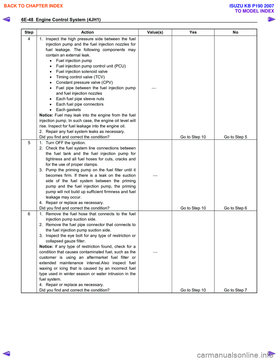
Step Action Value(s) Yes No
4 1. Inspect the high pressure side between the fuel
injection pump and the fuel injection nozzles for
fuel leakage. The following components may
contain an external leak. • Fuel injection pump
• Fuel injection pump control unit (PCU)
• Fuel injection solenoid valve
• Timing control valve (TCV)
• Constant pressure valve (CPV)
• Fuel pipe between the fuel injection pump
and fuel injection nozzles
• Each fuel pipe sleeve nuts
• Each fuel pipe connectors
• Each gaskets
Notice: Fuel may leak into the engine from the fuel
injection pump. In such case, the engine oil level will
rise. Inspect for fuel leakage into the engine oil.
2. Repair any fuel system leaks as necessary.
Did you find and correct the condition?
Go to Step 10 Go to Step 5
5 1. Turn OFF the ignition. 2. Check the fuel system line connections between the fuel tank and the fuel injection pump for
tightness and all fuel hoses for cuts, cracks and
for the use of proper clamps.
3. Pump the priming pump on the fuel filter until it becomes firm. If there is a leak on the suction
side of the fuel system between the priming
pump and the fuel injection pump, the priming
pump will not build up sufficient firmness and fuel
leakage may occur.
4. Repair or replace as necessary.
Did you find and correct the condition?
Go to Step 10 Go to Step 6
6 1. Remove the fuel hose that connects to the fuel injection pump suction side.
2. Remove the fuel pipe connector that connects to the fuel injection pump suction side.
3. Inspect the eye bolt for any type of restriction or collapsed gauze filter.
Notice: If any type of restriction found, check for a
condition that causes contaminated fuel, such as the
customer is using an aftermarket fuel filter or
extended maintenance interval.Also inspect fuel
waxing or icing that is caused by an incorrect fuel
type used in winter season or water intrusion in the
fuel system.
4. Repair or replace as necessary.
Did you find and correct the condition?
Go to Step 10 Go to Step 7
BACK TO CHAPTER INDEX
TO MODEL INDEX
ISUZU KB P190 2007
Page 1317 of 6020
Engine Control System (4JH1) 6E-283
Description And Operation
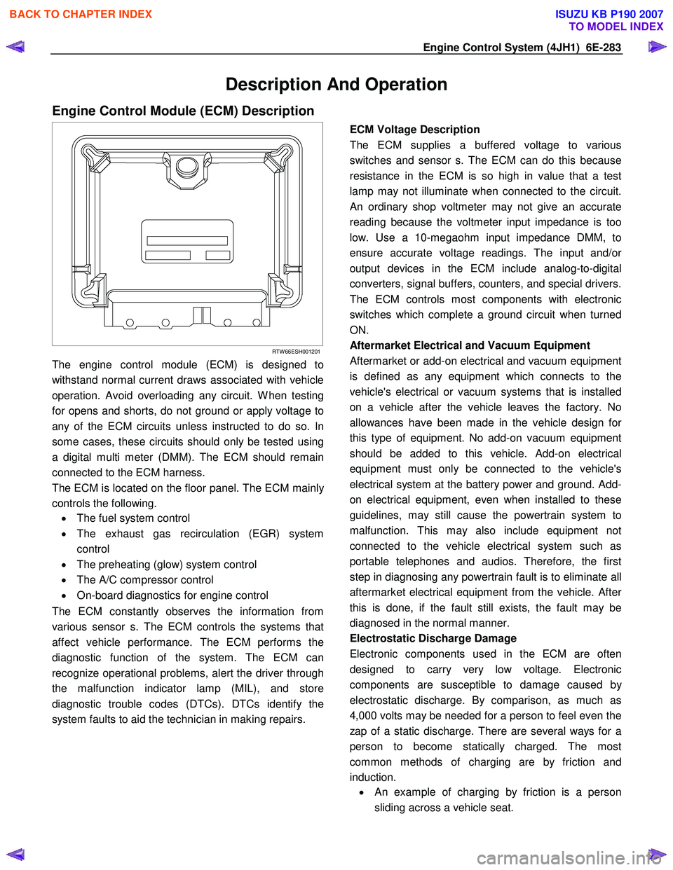
Engine Control Module (ECM) Description
RTW 66ESH001201
The engine control module (ECM) is designed to
withstand normal current draws associated with vehicle
operation. Avoid overloading any circuit. W hen testing
for opens and shorts, do not ground or apply voltage to
any of the ECM circuits unless instructed to do so. In
some cases, these circuits should only be tested using
a digital multi meter (DMM). The ECM should remain
connected to the ECM harness.
The ECM is located on the floor panel. The ECM mainl
y
controls the following.
• The fuel system control
• The exhaust gas recirculation (EGR) system
control
• The preheating (glow) system control
• The A/C compressor control
• On-board diagnostics for engine control
The ECM constantly observes the information from
various sensor s. The ECM controls the systems that
affect vehicle performance. The ECM performs the
diagnostic function of the system. The ECM can
recognize operational problems, alert the driver through
the malfunction indicator lamp (MIL), and store
diagnostic trouble codes (DTCs). DTCs identify the
system faults to aid the technician in making repairs.
ECM Voltage Description
The ECM supplies a buffered voltage to various
switches and sensor s. The ECM can do this because
resistance in the ECM is so high in value that a test
lamp may not illuminate when connected to the circuit.
An ordinary shop voltmeter may not give an accurate
reading because the voltmeter input impedance is too
low. Use a 10-megaohm input impedance DMM, to
ensure accurate voltage readings. The input and/o
r
output devices in the ECM include analog-to-digital
converters, signal buffers, counters, and special drivers.
The ECM controls most components with electronic
switches which complete a ground circuit when turned
ON.
Aftermarket Electrical and Vacuum Equipment
Aftermarket or add-on electrical and vacuum equipment
is defined as any equipment which connects to the
vehicle's electrical or vacuum systems that is installed
on a vehicle after the vehicle leaves the factory. No
allowances have been made in the vehicle design fo
r
this type of equipment. No add-on vacuum equipment
should be added to this vehicle. Add-on electrical
equipment must only be connected to the vehicle's
electrical system at the battery power and ground. Add-
on electrical equipment, even when installed to these
guidelines, may still cause the powertrain system to
malfunction. This may also include equipment not
connected to the vehicle electrical system such as
portable telephones and audios. Therefore, the first
step in diagnosing any powertrain fault is to eliminate all
aftermarket electrical equipment from the vehicle. Afte
r
this is done, if the fault still exists, the fault may be
diagnosed in the normal manner.
Electrostatic Discharge Damage
Electronic components used in the ECM are often
designed to carry very low voltage. Electronic
components are susceptible to damage caused b
y
electrostatic discharge. By comparison, as much as
4,000 volts may be needed for a person to feel even the
zap of a static discharge. There are several ways for a
person to become statically charged. The most
common methods of charging are by friction and
induction. •
An example of charging by friction is a person
sliding across a vehicle seat.
BACK TO CHAPTER INDEX
TO MODEL INDEX
ISUZU KB P190 2007
Page 1449 of 6020
ENGINE MECHANICAL (4JK1/4JJ1) 6A-89
Installation
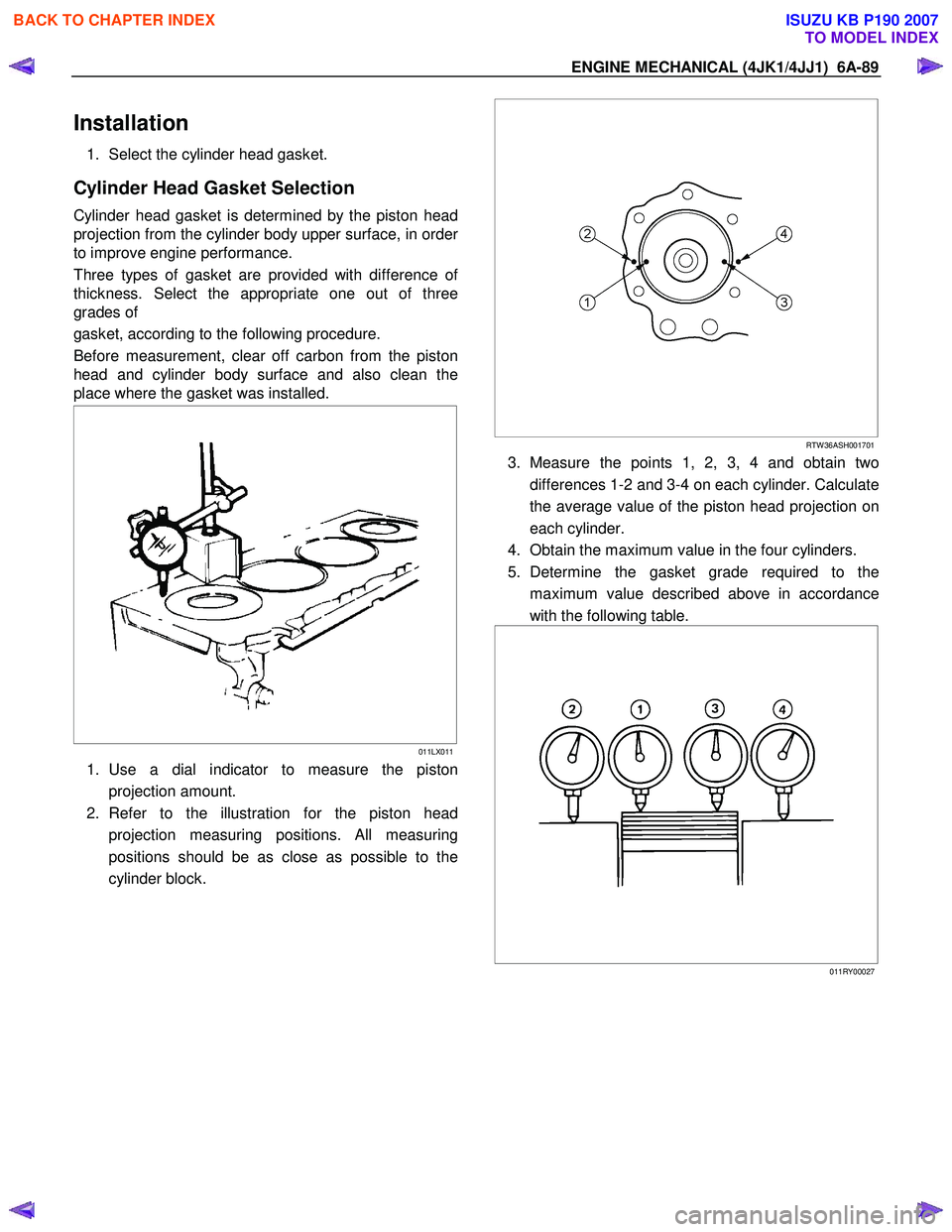
1. Select the cylinder head gasket.
Cylinder Head Gasket Selection
Cylinder head gasket is determined by the piston head
projection from the cylinder body upper surface, in orde
r
to improve engine performance.
Three types of gasket are provided with difference o
f
thickness. Select the appropriate one out of three
grades of
gasket, according to the following procedure.
Before measurement, clear off carbon from the piston
head and cylinder body surface and also clean the
place where the gasket was installed.
011LX011
1. Use a dial indicator to measure the piston
projection amount.
2. Refer to the illustration for the piston head projection measuring positions. All measuring
positions should be as close as possible to the
cylinder block.
RTW 36ASH001701
3. Measure the points 1, 2, 3, 4 and obtain two
differences 1-2 and 3-4 on each cylinder. Calculate
the average value of the piston head projection on
each cylinder.
4. Obtain the maximum value in the four cylinders.
5. Determine the gasket grade required to the maximum value described above in accordance
with the following table.
011RY00027
BACK TO CHAPTER INDEX
TO MODEL INDEX
ISUZU KB P190 2007