2007 ISUZU KB P190 fault code reset
[x] Cancel search: fault code resetPage 3826 of 6020
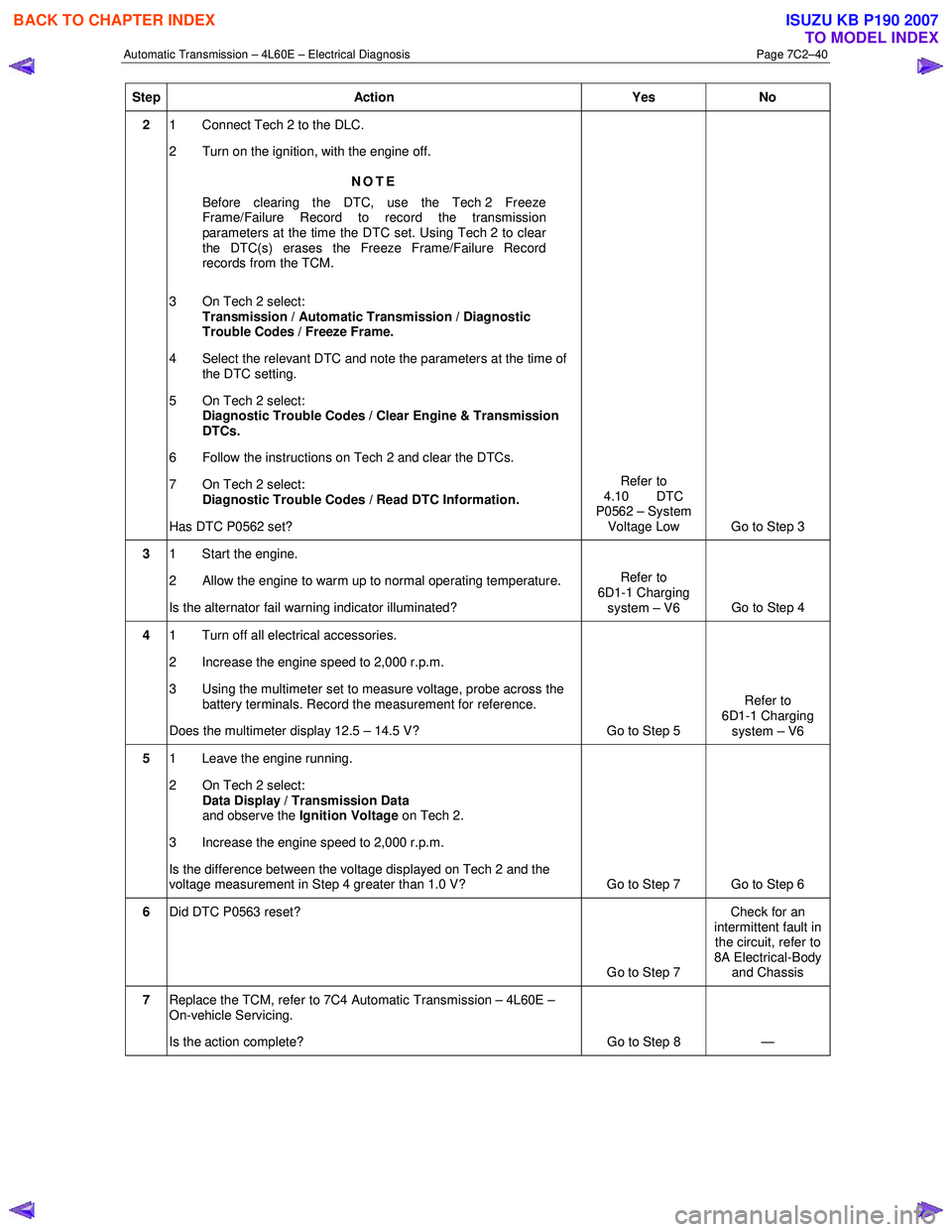
Automatic Transmission – 4L60E – Electrical Diagnosis Page 7C2–40
Step Action Yes No
2 1 Connect Tech 2 to the DLC.
2 Turn on the ignition, with the engine off.
NOTE
Before clearing the DTC, use the Tech 2 Freeze
Frame/Failure Record to record the transmission
parameters at the time the DTC set. Using Tech 2 to clear
the DTC(s) erases the Freeze Frame/Failure Record
records from the TCM.
3 On Tech 2 select: Transmission / Automatic Transmission / Diagnostic
Trouble Codes / Freeze Frame.
4 Select the relevant DTC and note the parameters at the time of the DTC setting.
5 On Tech 2 select:
Diagnostic Trouble Codes / Clear Engine & Transmission
DTCs.
6 Follow the instructions on Tech 2 and clear the DTCs.
7 On Tech 2 select: Diagnostic Trouble Codes / Read DTC Information.
Has DTC P0562 set? Refer to
4.10 DTC
P0562 – System
Voltage Low Go to Step 3
3 1 Start the engine.
2 Allow the engine to warm up to normal operating temperature.
Is the alternator fail warning indicator illuminated? Refer to
6D1-1 Charging system – V6 Go to Step 4
4 1 Turn off all electrical accessories.
2 Increase the engine speed to 2,000 r.p.m.
3 Using the multimeter set to measure voltage, probe across the battery terminals. Record the measurement for reference.
Does the multimeter display 12.5 – 14.5 V? Go to Step 5 Refer to
6D1-1 Charging system – V6
5 1 Leave the engine running.
2 On Tech 2 select: Data Display / Transmission Data
and observe the Ignition Voltage on Tech 2.
3 Increase the engine speed to 2,000 r.p.m.
Is the difference between the voltage displayed on Tech 2 and the
voltage measurement in Step 4 greater than 1.0 V? Go to Step 7 Go to Step 6
6 Did DTC P0563 reset?
Go to Step 7 Check for an
intermittent fault in the circuit, refer to
8A Electrical-Body and Chassis
7 Replace the TCM, refer to 7C4 Automatic Transmission – 4L60E –
On-vehicle Servicing.
Is the action complete? Go to Step 8 —
BACK TO CHAPTER INDEX
TO MODEL INDEX
ISUZU KB P190 2007
Page 3827 of 6020
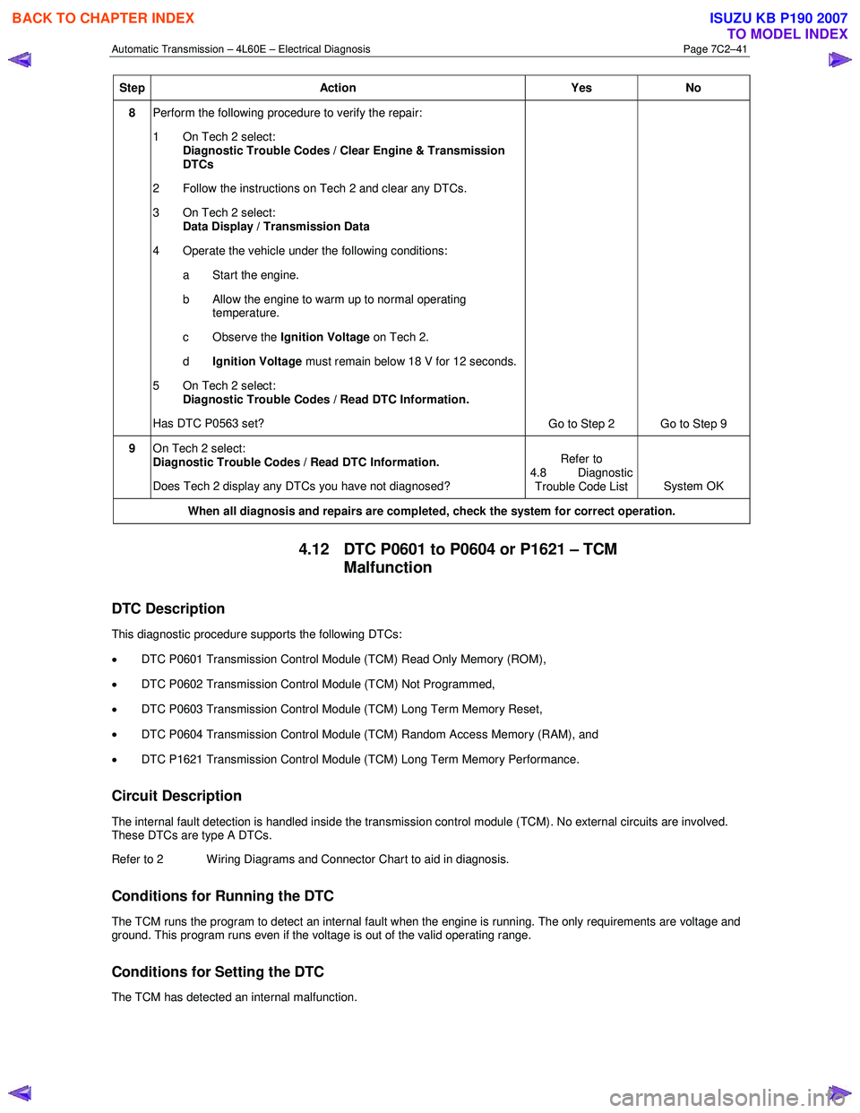
Automatic Transmission – 4L60E – Electrical Diagnosis Page 7C2–41
Step Action Yes No
8 Perform the following procedure to verify the repair:
1 On Tech 2 select: Diagnostic Trouble Codes / Clear Engine & Transmission
DTCs
2 Follow the instructions on Tech 2 and clear any DTCs.
3 On Tech 2 select: Data Display / Transmission Data
4 Operate the vehicle under the following conditions: a Start the engine.
b Allow the engine to warm up to normal operating temperature.
c Observe the Ignition Voltage on Tech 2.
d Ignition Voltage must remain below 18 V for 12 seconds.
5 On Tech 2 select:
Diagnostic Trouble Codes / Read DTC Information.
Has DTC P0563 set? Go to Step 2 Go to Step 9
9 On Tech 2 select:
Diagnostic Trouble Codes / Read DTC Information.
Does Tech 2 display any DTCs you have not diagnosed? Refer to
4.8 Diagnostic Trouble Code List System OK
When all diagnosis and repairs are completed, check the
system for correct operation.
4.12 DTC P0601 to P0604 or P1621 – TCM
Malfunction
DTC Description
This diagnostic procedure supports the following DTCs:
• DTC P0601 Transmission Control Module (TCM) Read Only Memory (ROM),
• DTC P0602 Transmission Control Module (TCM) Not Programmed,
• DTC P0603 Transmission Control Module (TCM) Long Term Memory Reset,
• DTC P0604 Transmission Control Module (TCM) Random Access Memory (RAM), and
• DTC P1621 Transmission Control Module (TCM) Long Term Memory Performance.
Circuit Description
The internal fault detection is handled inside the transmission control module (TCM). No external circuits are involved.
These DTCs are type A DTCs.
Refer to 2 W iring Diagrams and Connector Chart to aid in diagnosis.
Conditions for Running the DTC
The TCM runs the program to detect an internal fault when the engine is running. The only requirements are voltage and
ground. This program runs even if the voltage is out of the valid operating range.
Conditions for Setting the DTC
The TCM has detected an internal malfunction.
BACK TO CHAPTER INDEX
TO MODEL INDEX
ISUZU KB P190 2007
Page 3855 of 6020
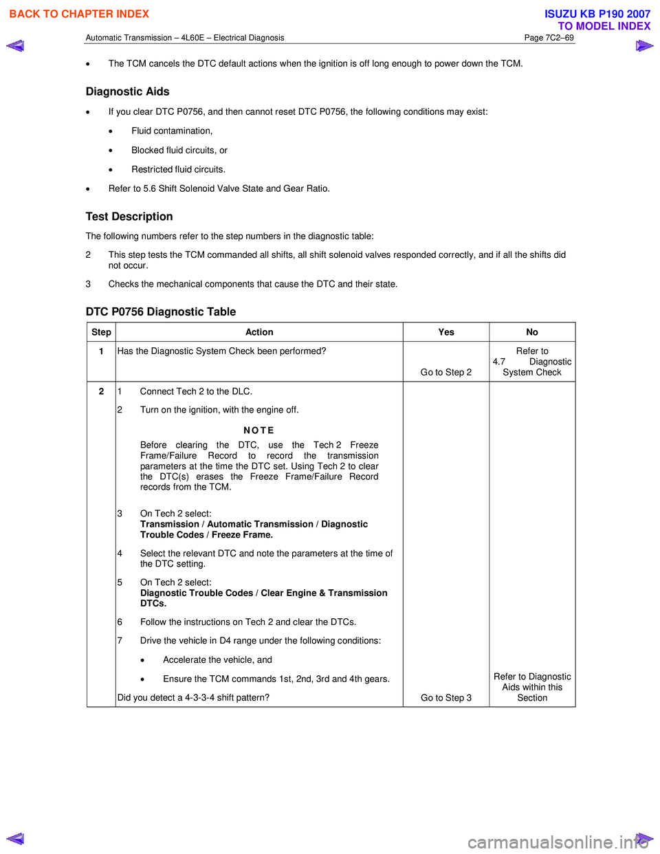
Automatic Transmission – 4L60E – Electrical Diagnosis Page 7C2–69
• The TCM cancels the DTC default actions when the ignition is off long enough to power down the TCM.
Diagnostic Aids
•
If you clear DTC P0756, and then cannot reset DTC P0756, the following conditions may exist:
• Fluid contamination,
• Blocked fluid circuits, or
• Restricted fluid circuits.
• Refer to 5.6 Shift Solenoid Valve State and Gear Ratio.
Test Description
The following numbers refer to the step numbers in the diagnostic table:
2 This step tests the TCM commanded all shifts, all shift solenoid valves responded correctly, and if all the shifts did not occur.
3 Checks the mechanical components that cause the DTC and their state.
DTC P0756 Diagnostic Table
Step Action Yes No
1 Has the Diagnostic System Check been performed?
Go to Step 2 Refer to
4.7 Diagnostic System Check
2 1 Connect Tech 2 to the DLC.
2 Turn on the ignition, with the engine off.
NOTE
Before clearing the DTC, use the Tech 2 Freeze
Frame/Failure Record to record the transmission
parameters at the time the DTC set. Using Tech 2 to clear
the DTC(s) erases the Freeze Frame/Failure Record
records from the TCM.
3 On Tech 2 select: Transmission / Automatic Transmission / Diagnostic
Trouble Codes / Freeze Frame.
4 Select the relevant DTC and note the parameters at the time of the DTC setting.
5 On Tech 2 select:
Diagnostic Trouble Codes / Clear Engine & Transmission
DTCs.
6 Follow the instructions on Tech 2 and clear the DTCs.
7 Drive the vehicle in D4 range under the following conditions:
• Accelerate the vehicle, and
• Ensure the TCM commands 1st, 2nd, 3rd and 4th gears.
Did you detect a 4-3-3-4 shift pattern? Go to Step 3 Refer to Diagnostic
Aids within this
Section
BACK TO CHAPTER INDEX
TO MODEL INDEX
ISUZU KB P190 2007
Page 5874 of 6020

IMMOBILIZER CONTROL SYSTEM (4JK1/4JJ1/HFV6) 11A-23
DTC B0002
Description
The electrically erasable programmable read only
memory (EEPROM) memorizes immobilizer security
code and transponder key information. If the ICU
detects immobilizer security code is not programmed
into the ICU, this DTC will set.
Condition for Setting the DTC • The ICU detects that the security code is not programmed.
Action Taken When the DTC Sets • The engine will fail to run if the fault occurs before starting the engine. Condition for Clearing the DTC
• A current DTC clears once ignition cycle has occurred without the fault recurring.
• A history DTC will clear after 50 consecutive ignition cycles, if the condition for malfunction is no
longer present.
• Use a scan tool to clear the DTC.
Diagnostic Aids • Non-programmed ICU sets this DTC.
Circuit/ System Testing DTC B0002
Step Action Value(s)Yes No
1 Did you perform the Diagnostic System Check -
Immobilizer Controls? —
Go to Step 2 Go to Diagnostic
System Check - Immobilizer Controls
2 1. Install a scan tool.
2. Turn OFF the ignition for 30 seconds.
3. Turn ON the ignition, with the engine OFF.
4. Monitor the DTC Information with a scan tool.
Does the DTC fail this ignition? —
Go to Step 3 Go to Diagnostic
Aids
3 Program immobilizer security information into the
ICU. Refer to Resetting and Programming
Guidelines in this section.
Did you complete the programming? —
Go to Step 4
—
41. Clear the DTCs with a scan tool.
2. Turn OFF the ignition for 30 seconds.
3. Turn ON the ignition.
Did the DTC fail this ignition? —
Go to Step 3 Go to Step 5
5 Observe the DTC Information with a scan tool.
Are there any DTCs that you have not diagnosed? —
Go to DTC List System OK
BACK TO CHAPTER INDEX
TO MODEL INDEX
ISUZU KB P190 2007
Page 5880 of 6020

IMMOBILIZER CONTROL SYSTEM (4JK1/4JJ1/HFV6) 11A-29
DTC B0009
Description
The electrically erasable programmable read only
memory (EEPROM) memorizes immobilizer security
code and transponder key information. If the ICU
detects any transponder key is not programmed into
the ICU, this DTC will set.
Condition for Running the DTC • The ignition switch is ON.
Condition for Setting the DTC • The ICU detects any transponder key is not programmed. Action Taken When the DTC Sets
• The engine will fail to run if the fault occurs before starting the engine.
Condition for Clearing the DTC • A current DTC clears once ignition cycle has occurred without the fault recurring.
• A history DTC will clear after 50 consecutive ignition cycles, if the condition for malfunction is no
longer present.
• Use a scan tool to clear the DTC.
Circuit/ System Testing DTC B0009
Step Action Value(s)Yes No
1 Did you perform the Diagnostic System Check -
Immobilizer Controls? —
Go to Step 2 Go to Diagnostic
System Check - Immobilizer Controls
2 1. Install a scan tool.
2. Turn OFF the ignition for 30 seconds.
3. Turn ON the ignition, with the engine OFF.
4. Monitor the DTC Information with a scan tool.
Is DTC B0002 also set? —
Go to DTC B0002 Go to Step 3
3 Program transponder key information into the ICU.
Refer to Resetting and Programming Guidelines in
this section.
Did you complete the programming? —
Go to Step 4
—
41. Clear the DTCs with a scan tool.
2. Turn OFF the ignition for 30 seconds.
3. Turn ON the ignition.
Did the DTC fail this ignition? —
Go to Step 3 Go to Step 5
5 Observe the DTC Information with a scan tool.
Are there any DTCs that you have not diagnosed? —
Go to DTC List System OK
BACK TO CHAPTER INDEX
TO MODEL INDEX
ISUZU KB P190 2007
Page 5899 of 6020
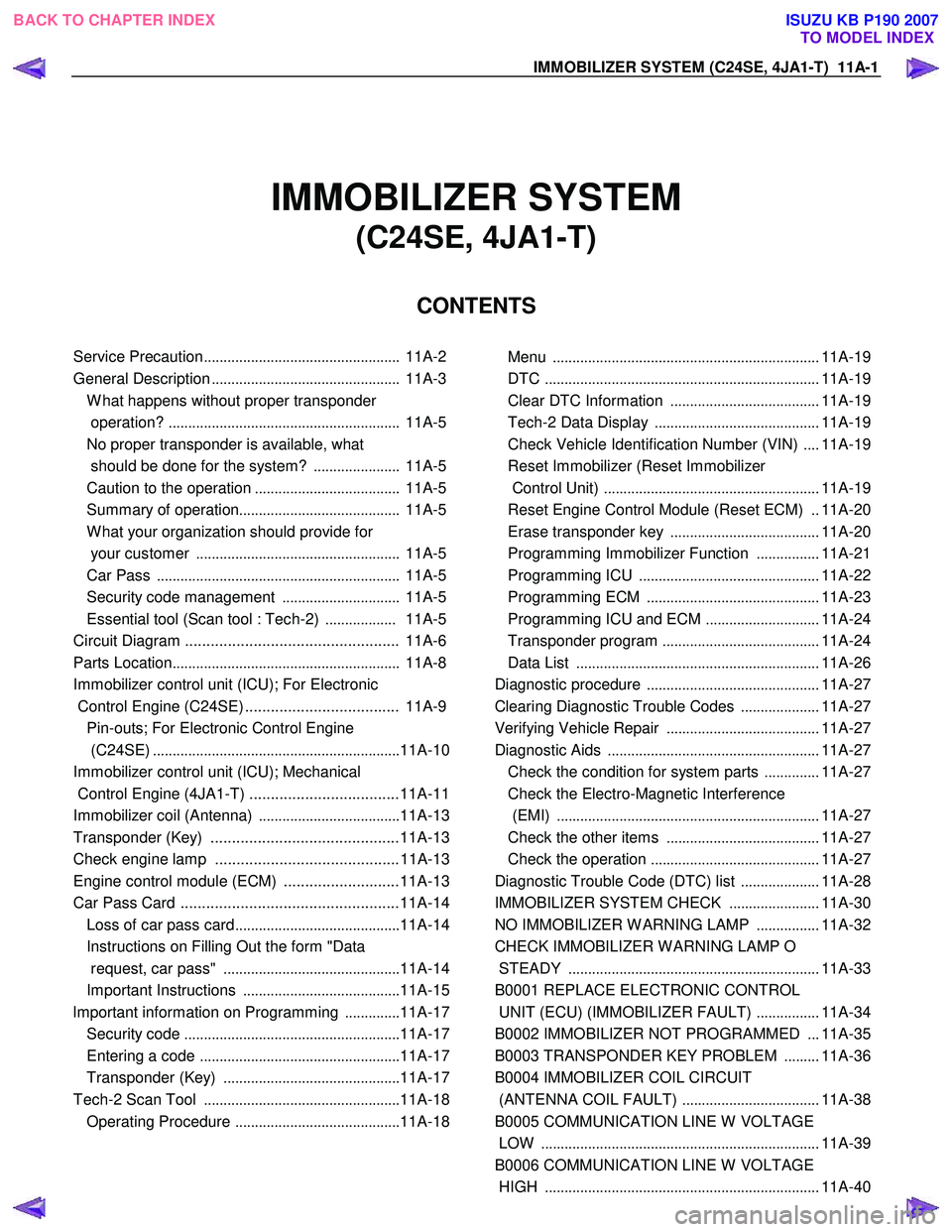
IMMOBILIZER SYSTEM (C24SE, 4JA1-T) 11A-1
IMMOBILIZER SYSTEM
(C24SE, 4JA1-T)
CONTENTS
Service Precaution .................................................. 11A-2
General Description ................................................ 11A-3
W hat happens without proper transponder
operation? ........................................................... 11A-5
No proper transponder is available, what
should be done for the system? ...................... 11A-5
Caution to the operation ..................................... 11A-5
Summary of operation ......................................... 11A-5
W hat your organization should provide for
your customer .................................................... 11A-5
Car Pass .............................................................. 11A-5
Security code management .............................. 11A-5
Essential tool (Scan tool : Tech-2) .................. 11A-5
Circuit Diagram .................................................. 11A-6
Parts Location .......................................................... 11A-8
Immobilizer control unit (ICU); For Electronic
Control Engine (C24SE) .................................... 11A-9
Pin-outs; For Electronic Control Engine
(C24SE) ............................................................... 11A-10
Immobilizer control unit (ICU); Mechanical
Control Engine (4JA1-T) ...................................11A-11
Immobilizer coil (Antenna) ....................................11A-13
Transponder (Key) ............................................11A-13
Check engine lamp ...........................................11A-13
Engine control module (ECM) ...........................11A-13
Car Pass Card ...................................................11A-14 Loss of car pass card .......................................... 11A-14
Instructions on Filling Out the form "Data
request, car pass" ............................................. 11A-14
Important Instructions ........................................ 11A-15
lmportant information on Programming ..............11A-17
Security code ....................................................... 11A-17
Entering a code ................................................... 11A-17
Transponder (Key) ............................................. 11A-17
Tech-2 Scan Tool .................................................. 11A-18
Operating Procedure .......................................... 11A-18
Menu .................................................................... 11A-19
DTC ...................................................................... 11A-19
Clear DTC Information ......................................11A-19
Tech-2 Data Display .......................................... 11A-19
Check Vehicle Identification Number (VIN) ....11A-19
Reset Immobilizer (Reset Immobilizer
Control Unit) ....................................................... 11A-19
Reset Engine Control Module (Reset ECM) ..11A-20
Erase transponder key ......................................11A-20
Programming Immobilizer Function ................11A-21
Programming ICU .............................................. 11A-22
Programming ECM ............................................ 11A-23
Programming ICU and ECM .............................11A-24
Transponder program ........................................ 11A-24
Data List .............................................................. 11A-26
Diagnostic procedure ............................................ 11A-27
Clearing Diagnostic Trouble Codes ....................11A-27
Verifying Vehicle Repair .......................................11A-27
Diagnostic Aids ...................................................... 11A-27
Check the condition for system parts ..............11A-27
Check the Electro-Magnetic Interference
(EMI) ................................................................... 11A-27
Check the other items .......................................11A-27
Check the operation ........................................... 11A-27
Diagnostic Trouble Code (DTC) list ....................11A-28
IMMOBILIZER SYSTEM CHECK .......................11A-30
NO IMMOBILIZER W ARNING LAMP ................11A-32
CHECK IMMOBILIZER W ARNING LAMP O
STEADY ................................................................ 11A-33
B0001 REPLACE ELECTRONIC CONTROL
UNIT (ECU) (IMMOBILIZER FAULT) ................11A-34
B0002 IMMOBILIZER NOT PROGRAMMED ...11A-35
B0003 TRANSPONDER KEY PROBLEM .........11A-36
B0004 IMMOBILIZER COIL CIRCUIT
(ANTENNA COIL FAULT) ...................................11A-38
B0005 COMMUNICATION LINE W VOLTAGE
LOW ....................................................................... 11A-39
B0006 COMMUNICATION LINE W VOLTAGE
HIGH ...................................................................... 11A-40
BACK TO CHAPTER INDEX
TO MODEL INDEX
ISUZU KB P190 2007