2007 ISUZU KB P190 4wd switch
[x] Cancel search: 4wd switchPage 4418 of 6020
7A2-134 TRANSMISSION CONTROL SYSTEM (JR405E)
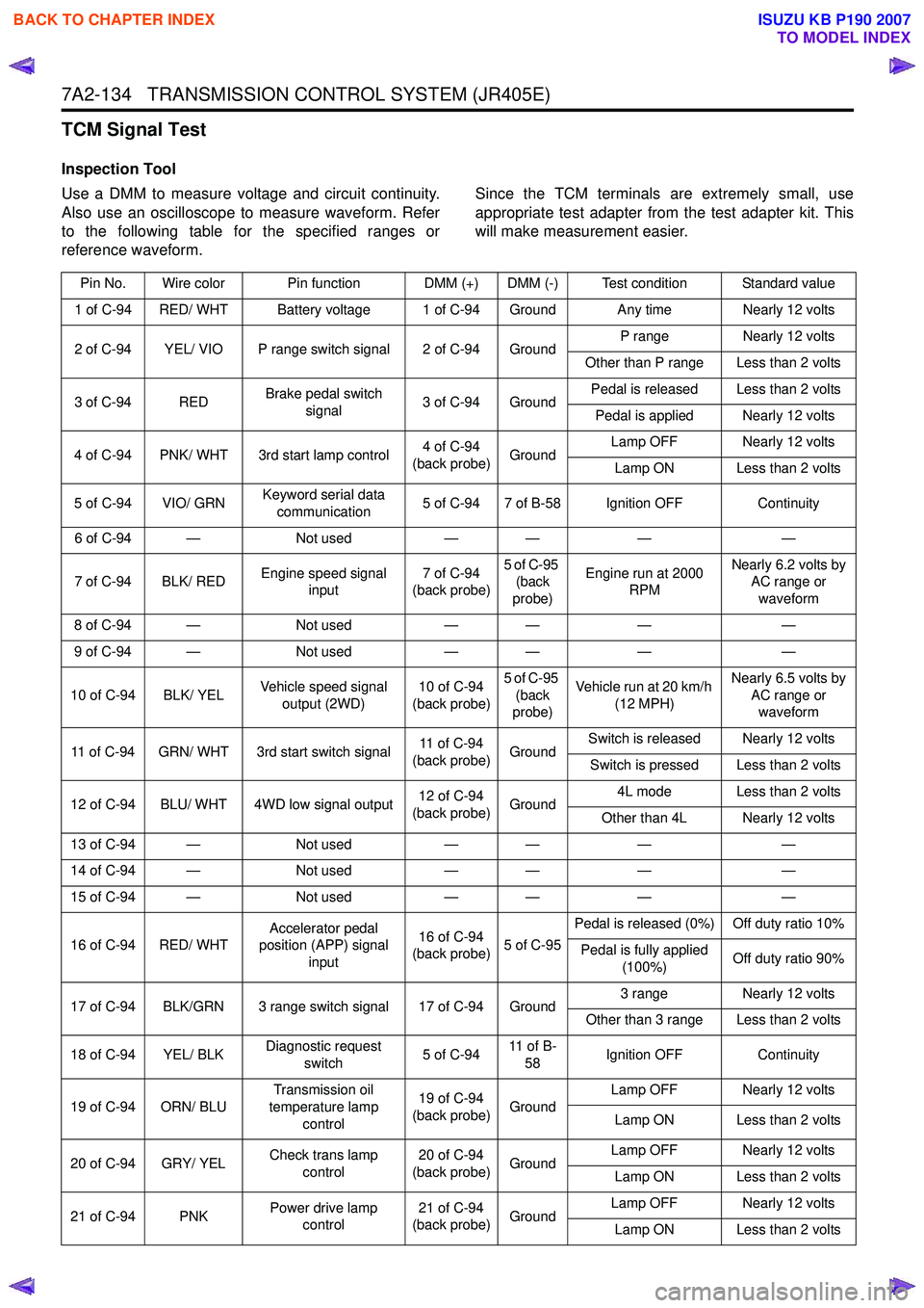
TCM Signal Test
Inspection Tool
Use a DMM to measure voltage and circuit continuity.
Also use an oscilloscope to measure waveform. Refer
to the following table for the specified ranges or
reference waveform. Since the TCM terminals are extremely small, use
appropriate test adapter from the test adapter kit. This
will make measurement easier.
Pin No. Wire color Pin function DMM (+) DMM (-) Test condition Standard value
1 of C-94 RED/ WHT Battery voltage 1 of C-94 Ground Any time Nearly 12 volts
2 of C-94 YEL/ VIO P range switch signal 2 of C-94 Ground P range
Nearly 12 volts
Other than P range Less than 2 volts
3 of C-94 RED Brake pedal switch
signal 3 of C-94 Ground Pedal is released Less than 2 volts
Pedal is applied Nearly 12 volts
4 of C-94 PNK/ WHT 3rd start lamp control 4 of C-94
(back probe) Ground Lamp OFF Nearly 12 volts
Lamp ON Less than 2 volts
5 of C-94 VIO/ GRN Keyword serial data
communication 5 of C-94 7 of B-58 Ignition OFF
Continuity
6 of C-94 — Not used— — ——
7 of C-94 BLK/ RED Engine speed signal
input 7 of C-94
(back probe) 5 of C-95
(back
probe) Engine run at 2000
RPM Nearly 6.2 volts by
AC range or
waveform
8 of C-94 — Not used— — ——
9 of C-94 — Not used— — ——
10 of C-94 BLK/ YEL Vehicle speed signal
output (2WD) 10 of C-94
(back probe) 5 of C-95
(back
probe) Vehicle run at 20 km/h
(12 MPH) Nearly 6.5 volts by
AC range or waveform
11 of C-94 GRN/ WHT 3rd start switch signal 11 of C-94
(back probe) GroundSwitch is released Nearly 12 volts
Switch is pressed Less than 2 volts
12 of C-94 BLU/ WHT 4WD low signal output 12 of C-94
(back probe) Ground 4L mode Less than 2 volts
Other than 4L Nearly 12 volts
13 of C-94 — Not used— — ——
14 of C-94 — Not used— — ——
15 of C-94 — Not used— — ——
16 of C-94 RED/ WHT Accelerator pedal
position (APP) signal
input 16 of C-94
(back probe) 5 of C-95Pedal is released (0%) Off duty ratio 10%
Pedal is fully applied (100%) Off duty ratio 90%
17 of C-94 BLK/GRN 3 range switch signal 17 of C-94 Ground 3 range
Nearly 12 volts
Other than 3 range Less than 2 volts
18 of C-94 YEL/ BLK Diagnostic request
switch 5 of C-9411 o f B -
58 Ignition OFF
Continuity
19 of C-94 ORN/ BLU Transmission oil
temperature lamp control 19 of C-94
(back probe) Ground Lamp OFF Nearly 12 volts
Lamp ON Less than 2 volts
20 of C-94 GRY/ YEL Check trans lamp
control 20 of C-94
(back probe) Ground Lamp OFF Nearly 12 volts
Lamp ON Less than 2 volts
21 of C-94 PNK Power drive lamp
control 21 of C-94
(back probe) Ground Lamp OFF Nearly 12 volts
Lamp ON Less than 2 volts
BACK TO CHAPTER INDEX
TO MODEL INDEX
ISUZU KB P190 2007
Page 4437 of 6020
TRANSMISSION CONTROL SYSTEM (JR405E) 7A2-153
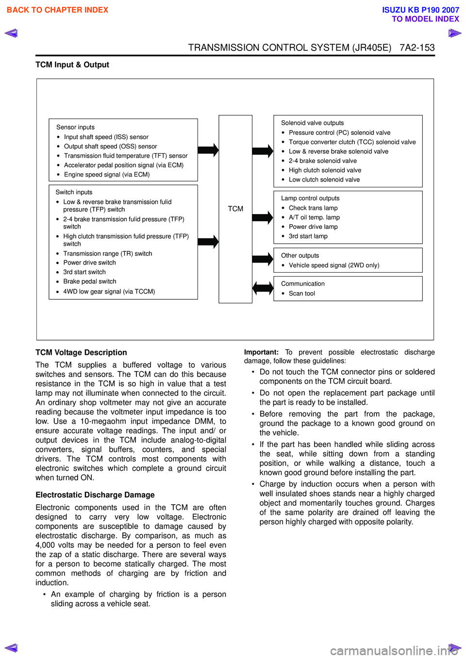
TCM Input & Output
TCM Voltage Description
The TCM supplies a buffered voltage to various
switches and sensors. The TCM can do this because
resistance in the TCM is so high in value that a test
lamp may not illuminate when connected to the circuit.
An ordinary shop voltmeter may not give an accurate
reading because the voltmeter input impedance is too
low. Use a 10-megaohm input impedance DMM, to
ensure accurate voltage readings. The input and/ or
output devices in the TCM include analog-to-digital
converters, signal buffers, counters, and special
drivers. The TCM controls most components with
electronic switches which complete a ground circuit
when turned ON.
Electrostatic Discharge Damage
Electronic components used in the TCM are often
designed to carry very low voltage. Electronic
components are susceptible to damage caused by
electrostatic discharge. By comparison, as much as
4,000 volts may be needed for a person to feel even
the zap of a static discharge. There are several ways
for a person to become statically charged. The most
common methods of charging are by friction and
induction.
• An example of charging by friction is a person sliding across a vehicle seat.
Important: To prevent possible electrostatic discharge
damage, follow these guidelines:
• Do not touch the TCM connector pins or soldered components on the TCM circuit board.
• Do not open the replacement part package until the part is ready to be installed.
• Before removing the part from the package, ground the package to a known good ground on
the vehicle.
• If the part has been handled while sliding across the seat, while sitting down from a standing
position, or while walking a distance, touch a
known good ground before installing the part.
• Charge by induction occurs when a person with well insulated shoes stands near a highly charged
object and momentarily touches ground. Charges
of the same polarity are drained off leaving the
person highly charged with opposite polarity.
Sensor inputs
Input shaft speed (ISS) sensor
Output shaft speed (OSS) sensor
Transmission fluid temperature (TFT) sensor
Accelerator pedal position signal (via ECM)
Engine speed signal (via ECM)
Switch inputs
Low & reverse brake transmission fulid
pressure (TFP) switch
2-4 brake transmission fulid pressure (TFP)
switch
High clutch transmission fulid pressure (TFP)
switch
Transmission range (TR) switch
Power drive switch
3rd start switch
Brake pedal switch
4WD low gear signal (via TCCM)
TCM
Solenoid valve outputs
Pressure control (PC) solenoid valve
Torque converter clutch (TCC) solenoid valve
Low & reverse brake solenoid valve
2-4 brake solenoid valve
High clutch solenoid valve
Low clutch solenoid valve
Other outputsVehicle speed signal (2WD only)
CommunicationScan tool
Lamp control outputsCheck trans lamp
A/T oil temp. lamp
Power drive lamp
3rd start lamp
BACK TO CHAPTER INDEX
TO MODEL INDEX
ISUZU KB P190 2007
Page 4440 of 6020

7A2-156 TRANSMISSION CONTROL SYSTEM (JR405E)
Gearshift Control & Shift Map Selection
The TCM commands each shift solenoid valve based
on the traveling mode switch (power drive/ 3rd start),
transmission range switch, the vehicle speed, the
accelerator pedal angle and other input signals, to
control the optimum gear position automatically. Shift
features have been set up to the TCM as shift map; the
normal mode is suited to normal travel, and the power
mode is used when the vehicle is loaded or the speed
accelerated. In addition, shift features used only for
high transmission fluid temperature, hill climbing, and
downward travel have been set up to the TCM. These
are automatically switched depending on the driving
conditions. When the transmission fluid temperature is
lower than 10 °C (50 °F), gearshift from the 3rd to the
4th is inhibited.
Shift Map
The TCM selects either of the following shift map
depending on the driving conditions. High Temperature Mode
Condition for setting the high temperature mode shift
map;
• Transmission fluid temperature is more than 122 °C
(252 °F) for 10 seconds.
Condition for canceling the high temperature mode shift
map;
• Transmission fluid temperature is less than 115 °C
(239 °F) for 10 seconds
Notice: High temperature mode may be set with
driving conditions other than the setting condition met
in order to protect from a thermal damage.
3rd Start Mode
Condition for setting the 3rd start mode shift map;
All of the following conditions are met:
• 3rd start switch is pressed
• Vehicle speed is less than 11 km/h (7 MPH)
• Transmission fluid is less than 115 °C (239 °F)
• Accelerator pedal position is less than 8%
• Selector lever is D range
Condition for canceling the 3rd start mode shift map;
Either of the following condition is met:
• 3rd start switch is pressed again
• Vehicle speed is more than 34 km/h (21 MPH)
• Selector lever is other than D range
4L Mode
Condition for setting the 4L mode shift map;
All of the following conditions are met:
• 4L switch is On
• Vehicle speed is more than 5 km/h (3 MPH)
Condition for canceling the 4L mode shift map;
Either of the following condition is met:
• 4L switch is On
• Vehicle speed is more than 5 km/h (3 MPH)
TCM
Sensor inputs
Input shaft speed (ISS) sensor
Output shaft speed (OSS) sensor
Transmission fluid temperature (TFT) sensor
Accelerator pedal position signal (via ECM)
Engine speed signal (via ECM)
Switch inputs
Transmission range (TR) switch
Power drive switch
3rd start switch
Brake pedal switch
4WD low gear signal (via TCCM)
Solenoid valve outputs
Low & reverse brake solenoid valve
2-4 brake solenoid valve
High clutch solenoid valve
Low clutch solenoid valve
Lamp control outputs
Power drive lamp
3rd start lamp
OFF
ON
OFF ON OFF
OFF
Low
Priority Shift map 3rd start
lamp Power drive
lamp
High temperature mode
3rd start mode
4L mode
Down slope mode when
power drive SW Off
Down slope mode when
power drive SW On
Power drive mode
Up slope mode
Normal mode
High
BACK TO CHAPTER INDEX
TO MODEL INDEX
ISUZU KB P190 2007
Page 4877 of 6020
TRANSFER CONTROL SYSTEM 7D1-3
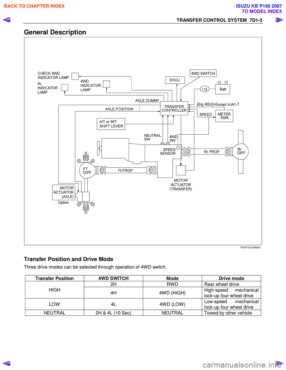
General Description
RTW 77DLF000501
Transfer Position and Drive Mode
Three drive modes can be selected through operation of 4W D switch.
Transfer Position 4WD SWITCH Mode Drive mode
2H RW D Rear wheel drive
HIGH
4H 4W D (HIGH) High-speed mechanical
lock-up four wheel drive
LOW 4L 4W D (LOW ) Low-speed mechanical
lock-up four wheel drive
NEUTRAL 2H & 4L (10 Sec) NEUTRAL Towed by other vehicle
BACK TO CHAPTER INDEX
TO MODEL INDEX
ISUZU KB P190 2007
Page 4879 of 6020
TRANSFER CONTROL SYSTEM 7D1-5
System Components
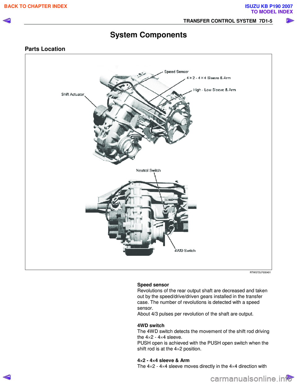
Parts Location
RTW 57DLF000401
Speed sensor
Revolutions of the rear output shaft are decreased and taken
out by the speed/drive/driven gears installed in the transfer
case. The number of revolutions is detected with a speed
sensor.
About 4/3 pulses per revolution of the shaft are output.
4WD switch
The 4W D switch detects the movement of the shift rod driving
the 4 ×2 - 4 ×4 sleeve.
PUSH open is achieved with the PUSH open switch when the
shift rod is at the 4 ×2 position.
4 ×
××
×
2 - 4 ×
××
×
4 sleeve & Arm
The 4 ×2 - 4 ×4 sleeve moves directly in the 4 ×4 direction with
BACK TO CHAPTER INDEX
TO MODEL INDEX
ISUZU KB P190 2007
Page 4880 of 6020
7D1-6 TRANSFER CONTROL SYSTEM
the 4×2 - 4 ×4 shift rod. W hen moving in 4 ×2 direction, a spring
standby mechanism is provided between the rod and sleeve so
that the rod is positioned at the 4 ×2 position, while the sleeve is
at the 4 ×4 position.
This mechanism is provided to protect the shift mechanism
from the force and to prevent movement of the sleeve
(torsional torque etc. of the drive system). By releasing the
preventive force, the sleeve can move to the 4 ×2 state by the
spring force.
Neutral switch
The neutral switch detects the movement of the shift rod
driving the high-low sleeve.
PUSH close is achieved with the PUSH close switch when the
shift rod is positioned between the High and the Low, at the
neutral state.
High-Low Sleeve & Arm
The spring standby mechanism is provided for the high-low
sleeve in both directions of the high-low shift rod. Therefore,
the rod position and the actual sleeve position may be offset in
some cases.
This system is provided to protect the shift mechanism from a
collision due to coincidence of the high and low phases of the
engaged splines. By giving rotational force to the preventing
phase coincidence, the splines are moved to the proper
engagement position by the spring force.
Shift actuator
The output shaft is rotated by the built-in motor and the transfer
position is switched.
Detection (limit) switches to detect the rotating angle of the
output shaft that is provided to the actuator at 4 positions.
These are connected to the transfer controller through the
vehicle harness to constantly transmit the actuator operating
angle and changes in its transfer status.
7B4-PDF2
4WD indicator (in meter panel)
This lamp indicates the following items:
Valve check
Drive condition (2W D-4W D)
Operating condition (2Hz: Actuator in operation, mechanism
standby)
Restrictions on operation (4Hz, including indication of
interrupted operation due
to excessive load)
BACK TO CHAPTER INDEX
TO MODEL INDEX
ISUZU KB P190 2007
Page 4881 of 6020
TRANSFER CONTROL SYSTEM 7D1-7
7B4-PDF3
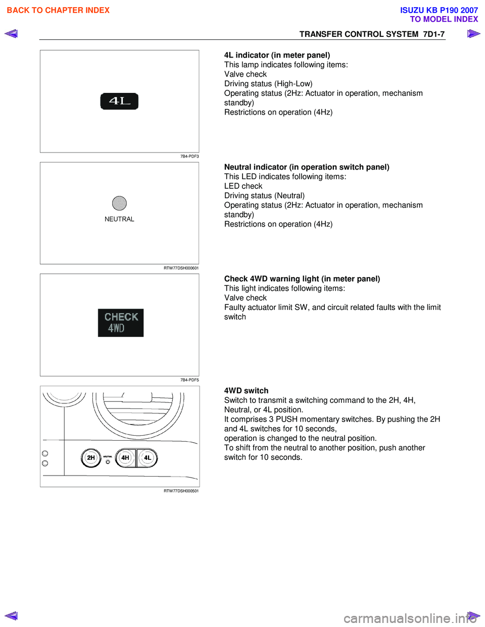
4L indicator (in meter panel)
This lamp indicates following items:
Valve check
Driving status (High-Low)
Operating status (2Hz: Actuator in operation, mechanism
standby)
Restrictions on operation (4Hz)
RTW 77DSH000601
Neutral indicator (in operation switch panel)
This LED indicates following items:
LED check
Driving status (Neutral)
Operating status (2Hz: Actuator in operation, mechanism
standby)
Restrictions on operation (4Hz)
7B4-PDF5
Check 4WD warning light (in meter panel)
This light indicates following items:
Valve check
Faulty actuator limit SW , and circuit related faults with the limit
switch
RTW 77DSH000501
4WD switch
Switch to transmit a switching command to the 2H, 4H,
Neutral, or 4L position.
It comprises 3 PUSH momentary switches. By pushing the 2H
and 4L switches for 10 seconds,
operation is changed to the neutral position.
To shift from the neutral to another position, push another
switch for 10 seconds.
BACK TO CHAPTER INDEX
TO MODEL INDEX
ISUZU KB P190 2007
Page 4886 of 6020

7D1-12 TRANSFER CONTROL SYSTEM
Functions of Switch and indicator Lamp
Transfer-related indicator lamp and switch function
Item 4WD
lamp 4L lamp Neutral
lamp Check
4WD
warning light 4WD
switch Actu ato r
detection (limit)
switches
LS1, LS2, LS3. and LS4
1 = on
2 = off Transfer
4WD
switch Transfer
neutral switch SOF
actuator switch Or
Axl e
dummy Remarks
2H Off Off Off Off No
operation 1,0,1,0 Open Open Open -----
4H start
of
operation Off Off Off Off 4H position
for 0.1
second 1,0,1,0 Open Open Open Switch
operation sensor
Start of
operation Blinking
(2HZ) Off Off Off No
operation 1,1,1,0
0,0,1,0
0,1,1,0
0,1,1,1 Open Open Open
2H to 4H
while
driving
During
operation
(Synchro) Blinking
(2HZ) Off Off Off No
operation 1,1,1,0
0,0,1,0
0,1,1,0
0,1,1,1 Open Open Open 2H to 4H
using
synchro and
retrial
During
operation (Axle
drive) Blinking
(2HZ) Off Off Off No
operation 0,0,1,1 Closed Open Open Axle drive
Axle
waiting Blinking
(2HZ) Off Off Off No
operation 0,0,1,1 Closed Open Open Axle drive
4H On Off Off Off No
operation 0,0,1,1 Closed Open Closed -----
4L start
of
operation On Off Off Off 4L position
for 0.1
second 0,0,1,1 Closed Open Closed Switch
operation sensor
Start of
operation On Blinking
(2HZ) Off Off No
operation 0,0,0,1
0,1,0,1 Closed Open Closed 4H to 4L
while
driving
During
operation (N) Off
Blinking
(2HZ) Off Off No
operation 0,0,0,1
0,1,0,1 Closed Closed Closed 4H to 4L
through neutral
During
operation (N) Off
Blinking
(2HZ) Off Off No
operation 0,1,0,0 Closed Closed Closed 4H to 4L
through neutral
During
operation (N) Off
Blinking
(2HZ) Off Off No
operation 1,1,0,0 Closed Closed Closed 4H to 4L
through neutral
4L
waiting On Blinking
(2HZ) Off Off No
operation 1,1,0,1 Closed Closed Closed 4H to 4L
while
waiting
4L On On Off Off No
operation 1,1,0,1 Closed Open Closed -----
4H start of
operation On Off Off Off 4H position
for 0.1
second 1,1,0,1 Closed Open Closed Switch
operation sensor
BACK TO CHAPTER INDEX
TO MODEL INDEX
ISUZU KB P190 2007