2007 ISUZU KB P190 air filter
[x] Cancel search: air filterPage 3938 of 6020
Automatic Transmission – 4L60E – On-vehicle Servicing Page 7C4–25
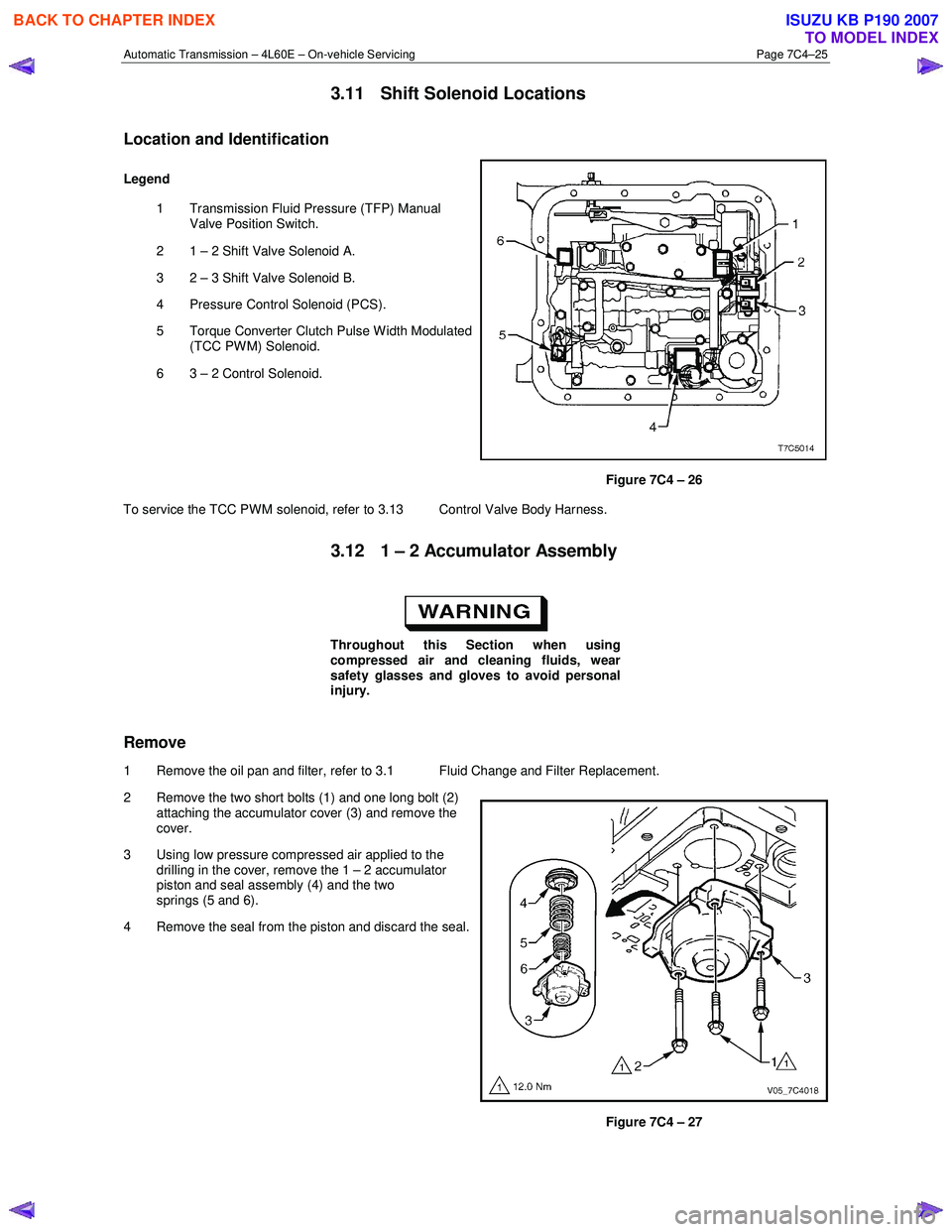
3.11 Shift Solenoid Locations
Location and Identification
Legend
1 Transmission Fluid Pressure (TFP) Manual Valve Position Switch.
2 1 – 2 Shift Valve Solenoid A.
3 2 – 3 Shift Valve Solenoid B.
4 Pressure Control Solenoid (PCS).
5 Torque Converter Clutch Pulse W idth Modulated (TCC PWM) Solenoid.
6 3 – 2 Control Solenoid.
Figure 7C4 – 26
To service the TCC PWM solenoid, refer to 3.13 Control Valve Body Harness.
3.12 1 – 2 Accumulator Assembly
Throughout this Section when using
compressed air and cleaning fluids, wear
safety glasses and gloves to avoid personal
injury.
Remove
1 Remove the oil pan and filter, refer to 3.1 Fluid Change and Filter Replacement.
2 Remove the two short bolts (1) and one long bolt (2) attaching the accumulator cover (3) and remove the
cover.
3 Using low pressure compressed air applied to the drilling in the cover, remove the 1 – 2 accumulator
piston and seal assembly (4) and the two
springs (5 and 6).
4 Remove the seal from the piston and discard the seal.
Figure 7C4 – 27
BACK TO CHAPTER INDEX
TO MODEL INDEX
ISUZU KB P190 2007
Page 3939 of 6020
Automatic Transmission – 4L60E – On-vehicle Servicing Page 7C4–26
Clean and Inspect
1 Clean all components in a commercially available cleaning fluid and blow dry using compressed air.
2 Inspect the springs and ensure they are not distorted or broken, replace as required.
3 Inspect all machined surfaces for damage, wear or burrs.
Reinstall
Reinstallation of the 1 – 2 accumulator assembly is the reverse of the removal procedure, noting the following:
1 Lubricate a new seal with petroleum jelly and install it to the piston. Ensure the piston seal does not bind in the piston groove.
2 Tighten the three bolts attaching the accumulator cover to the correct torque specification.
1 – 2 Accumulator cover attaching
bolt torque specification ..................................... 12.0 Nm
3.13 Control Valve Body Harness
Remove
1 Raise the vehicle and support in a safe manner, refer to 0A General Information for the location of support points.
2 As required, remove the oil pan and filter, refer to 3.1 Fluid Change and Filter Replacement.
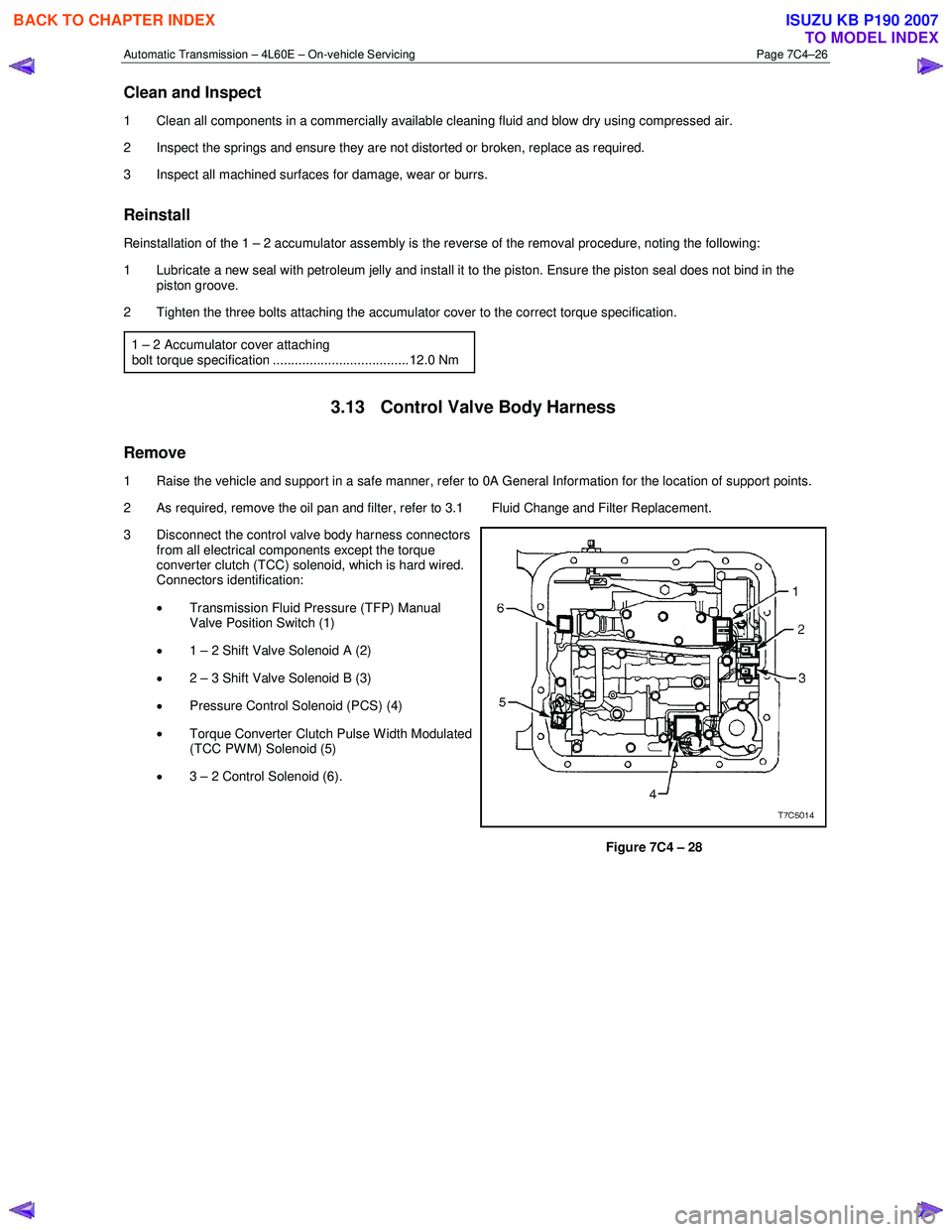
3 Disconnect the control valve body harness connectors from all electrical components except the torque
converter clutch (TCC) solenoid, which is hard wired.
Connectors identification:
• Transmission Fluid Pressure (TFP) Manual
Valve Position Switch (1)
• 1 – 2 Shift Valve Solenoid A (2)
• 2 – 3 Shift Valve Solenoid B (3)
• Pressure Control Solenoid (PCS) (4)
• Torque Converter Clutch Pulse W idth Modulated
(TCC PWM) Solenoid (5)
• 3 – 2 Control Solenoid (6).
Figure 7C4 – 28
BACK TO CHAPTER INDEX
TO MODEL INDEX
ISUZU KB P190 2007
Page 3949 of 6020
Automatic Transmission – 4L60E – On-vehicle Servicing Page 7C4–36
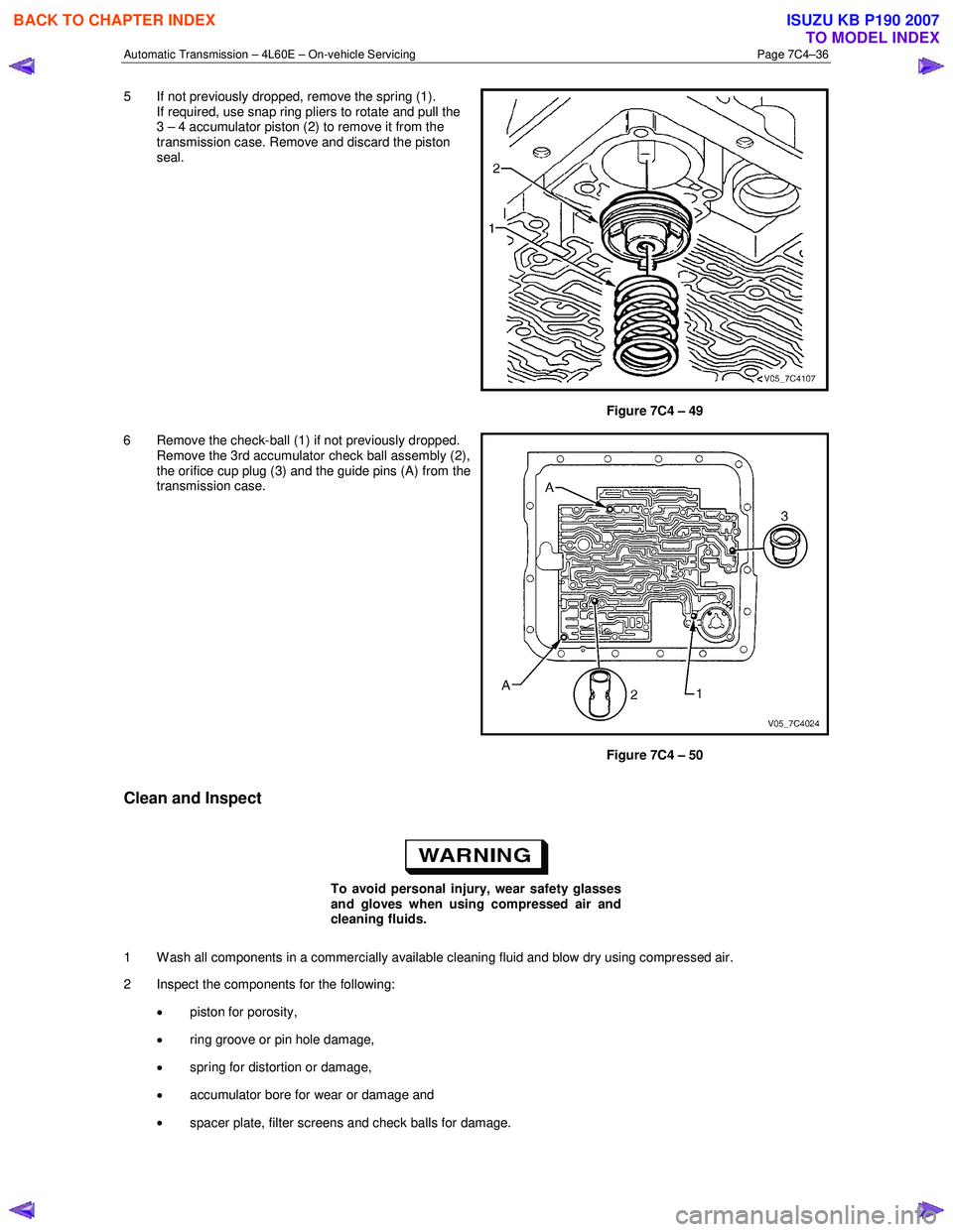
5 If not previously dropped, remove the spring (1).
If required, use snap ring pliers to rotate and pull the
3 – 4 accumulator piston (2) to remove it from the
transmission case. Remove and discard the piston
seal.
Figure 7C4 – 49
6 Remove the check-ball (1) if not previously dropped. Remove the 3rd accumulator check ball assembly (2),
the orifice cup plug (3) and the guide pins (A) from the
transmission case.
Figure 7C4 – 50
Clean and Inspect
To avoid personal injury, wear safety glasses
and gloves when using compressed air and
cleaning fluids.
1 W ash all components in a commercially available cleaning fluid and blow dry using compressed air.
2 Inspect the components for the following:
• piston for porosity,
• ring groove or pin hole damage,
• spring for distortion or damage,
• accumulator bore for wear or damage and
• spacer plate, filter screens and check balls for damage.
BACK TO CHAPTER INDEX
TO MODEL INDEX
ISUZU KB P190 2007
Page 4336 of 6020
7A2-52 TRANSMISSION CONTROL SYSTEM (JR405E)
DTC P0731, P0732, P0733 or P0734 (Flash Code 41, 42, 43 or 44)
Circuit Description
The TCM calculates the gear ratio based on the input
shaft speed signal from the input shaft speed (ISS)
sensor and the output speed signal from the output
shaft speed (OSS) sensor. The TCM compares the
known transmission gear ratio to the calculated ratio for
the selected gear ranges. If the TCM detects an
unknown transmission gear ratio two consecutive
driving cycles, this DTC will set.
Condition for Running the DTC • Other than DTCs P0731, P0732, P0733 and P0734 are not set.
• The ignition switch is ON.
• The transmission fluid temperature is more than 60 °C (140 °F).
• The input shaft speed is more than 1000 RPM.
• The vehicle speed is more than 10 km/h (6 MPH).
• The selector lever is forward range for longer than 2 seconds.
• The TCM is not under gearshift control.
Condition for Setting the DTC • The TCM detects that the output shaft speed is more than 500 RPM over the calculated speed
(based on the input shaft speed and the gear ratio)
for 7 seconds after each gearshift has completed.
Action Taken When the DTC Sets • The TCM blinks the Check Trans lamp on the second consecutive driving cycle when the
diagnostic runs and fails.
Condition for Clearing the DTC • The TCM turns OFF the Check Trans lamp when the diagnostic runs and does not fail. • A current DTC clears when the diagnostic runs and
does not fail.
Diagnostic Aids • If an intermittent condition is suspected, refer to Intermittent Conditions in this section.
• Electromagnetic interference in the ISS sensor or OSS sensor circuits may set this DTC.
• An intermittent ISS sensor or OSS sensor signal pulse may set this DTC.
• Ensure the ISS sensor and OSS sensor is tight.
• Use the Clutch, Brake, Solenoid and Pressure Switch Logic table to verify each component works
properly within the selected gear range.
• A transmission mechanical problem will cause this DTC to set.
• Sticking or contamination of shift valves may cause intermittent incorrect gear ratios.
• If multiple incorrect gear ratio codes are set, problem in fluid pressure, low ATF level, plugged
filter or oil pump problem may exist.
Notice: • Each DTC agrees with the following gear positions.
- P0731: 1st gear
- P0732: 2nd gear
- P0733: 3rd gear
- P0734: 4th gear
Schematic Reference: Transmission Controls
Schematics
Connector End View Reference: Transmission
Controls Connector End Views or TCM Connector End
Views
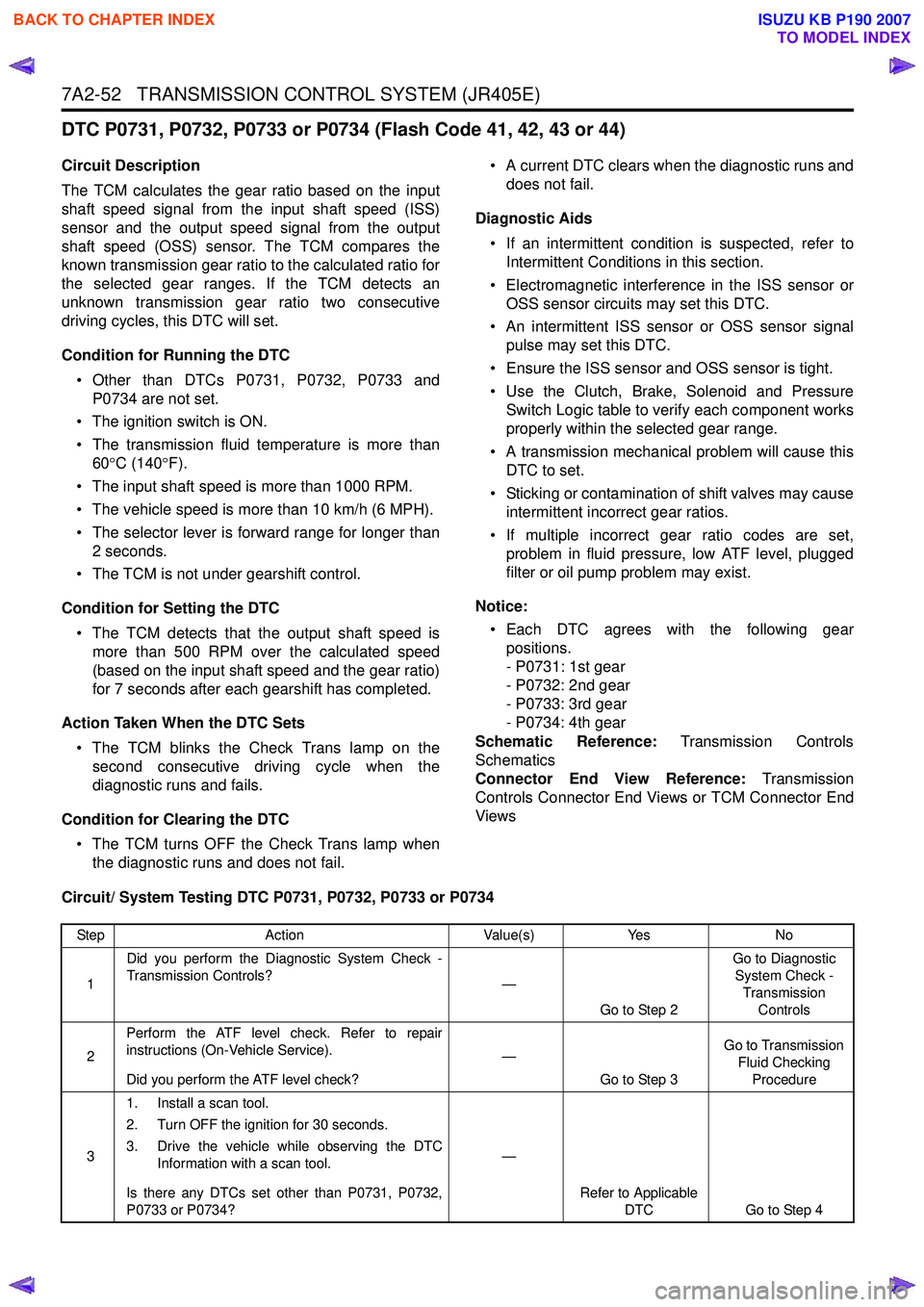
Circuit/ System Testing DTC P0731, P0732, P0733 or P0734
Step Action Value(s)Yes No
1 Did you perform the Diagnostic System Check -
Transmission Controls? —
Go to Step 2 Go to Diagnostic
System Check - Transmission Controls
2 Perform the ATF level check. Refer to repair
instructions (On-Vehicle Service).
Did you perform the ATF level check? —
Go to Step 3 Go to Transmission
Fluid Checking Procedure
3 1. Install a scan tool.
2. Turn OFF the ignition for 30 seconds.
3. Drive the vehicle while observing the DTC Information with a scan tool.
Is there any DTCs set other than P0731, P0732,
P0733 or P0734? —
Refer to Applicable DTC Go to Step 4
BACK TO CHAPTER INDEX
TO MODEL INDEX
ISUZU KB P190 2007
Page 4338 of 6020
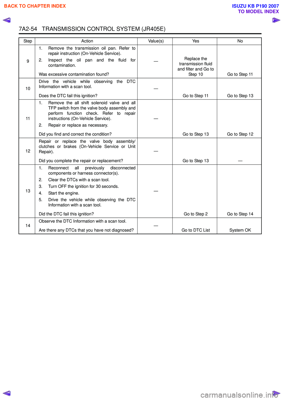
7A2-54 TRANSMISSION CONTROL SYSTEM (JR405E)
91. Remove the transmission oil pan. Refer to
repair instruction (On-Vehicle Service).
2. Inspect the oil pan and the fluid for contamination.
Was excessive contamination found? —
Replace the
transmission fluid
and filter and Go to Step 10 Go to Step 11
10 Drive the vehicle while observing the DTC
Information with a scan tool.
Does the DTC fail this ignition? —
Go to Step 11 Go to Step 13
11 1. Remove the all shift solenoid valve and all
TFP switch from the valve body assembly and
perform function check. Refer to repair
instructions (On-Vehicle Service).
2. Repair or replace as necessary.
Did you find and correct the condition? —
Go to Step 13 Go to Step 12
12 Repair or replace the valve body assembly/
clutches or brakes (On-Vehicle Service or Unit
Repair).
Did you complete the repair or replacement? —
Go to Step 13 —
13 1. Reconnect all previously disconnected
components or harness connector(s).
2. Clear the DTCs with a scan tool.
3. Turn OFF the ignition for 30 seconds.
4. Start the engine.
5. Drive the vehicle while observing the DTC Information with a scan tool.
Did the DTC fail this ignition? —
Go to Step 2 Go to Step 14
14 Observe the DTC Information with a scan tool.
Are there any DTCs that you have not diagnosed? —
Go to DTC List System OK
Step
Action Value(s)Yes No
BACK TO CHAPTER INDEX
TO MODEL INDEX
ISUZU KB P190 2007
Page 4500 of 6020
UNIT REPAIR (JR405E) 7A4-23
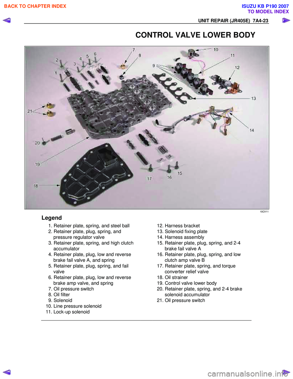
CONTROL VALVE LOWER BODY
10CV11
Legend
1. Retainer plate, spring, and steel ball
2. Retainer plate, plug, spring, and pressure regulator valve
3. Retainer plate, spring, and high clutch accumulator
4. Retainer plate, plug, low and reverse brake fail valve A, and spring
5. Retainer plate, plug, spring, and fail valve
6. Retainer plate, plug, low and reverse brake amp valve, and spring
7. Oil pressure switch
8. Oil filter
9. Solenoid
10. Line pressure solenoid
11. Lock-up solenoid
12. Harness bracket
13. Solenoid fixing plate
14. Harness assembly
15. Retainer plate, plug, spring, and 2-4 brake fail valve A
16. Retainer plate, plug, spring, and low clutch amp valve B
17. Retainer plate, spring, and torque converter relief valve
18. Oil strainer
19. Control valve lower body
20. Retainer plate, spring, and 2-4 brake solenoid accumulator
21. Oil pressure switch
BACK TO CHAPTER INDEX
TO MODEL INDEX
ISUZU KB P190 2007
Page 4501 of 6020
7A4-24 UNIT REPAIR (JR405E)
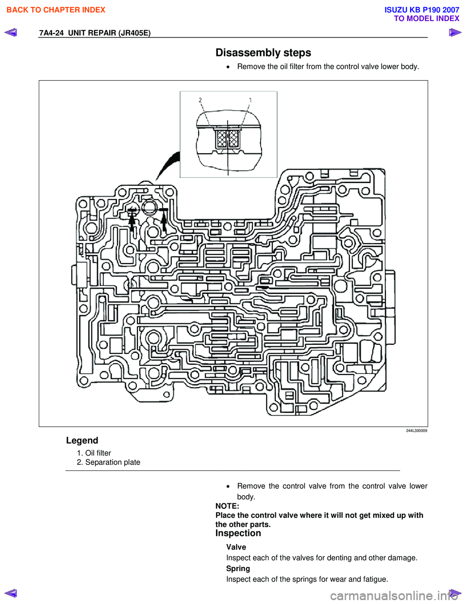
Disassembly steps
• Remove the oil filter from the control valve lower body.
244L300009
Legend
1. Oil filter
2. Separation plate
•
Remove the control valve from the control valve lower
body.
NOTE:
Place the control valve where it will not get mixed up with
the other parts.
Inspection
Valve
Inspect each of the valves for denting and other damage.
Spring
Inspect each of the springs for wear and fatigue.
BACK TO CHAPTER INDEX
TO MODEL INDEX
ISUZU KB P190 2007
Page 4504 of 6020
UNIT REPAIR (JR405E) 7A4-27
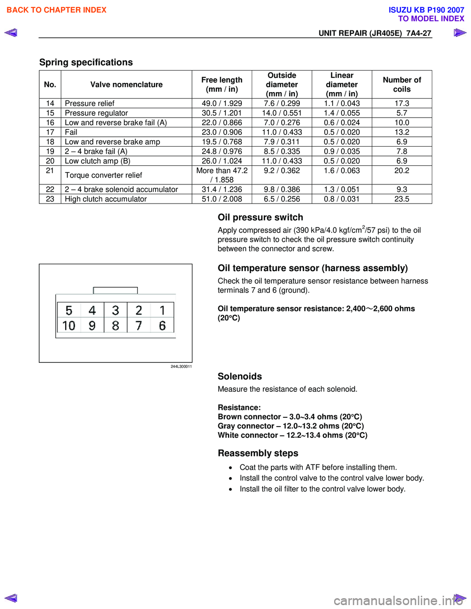
Spring specifications
No. Valve nomenclature Free length
(mm / in) Outside
diameter
(mm / in) Linear
diameter
(mm / in) Number of
coils
14 Pressure relief 49.0 / 1.929 7.6 / 0.299 1.1 / 0.043 17.3
15 Pressure regulator 30.5 / 1.201 14.0 / 0.551 1.4 / 0.055 5.7
16 Low and reverse brake fail (A) 22.0 / 0.866 7.0 / 0.276 0.6 / 0.024 10.0
17 Fail 23.0 / 0.906 11.0 / 0.433 0.5 / 0.020 13.2
18 Low and reverse brake amp 19.5 / 0.768 7.9 / 0.311 0.5 / 0.020 6.9
19 2 – 4 brake fail (A) 24.8 / 0.976 8.5 / 0.335 0.9 / 0.035 7.8
20 Low clutch amp (B) 26.0 / 1.024 11.0 / 0.433 0.5 / 0.020 6.9
21
Torque converter relief More than 47.2
/ 1.858 9.2 / 0.362 1.6 / 0.063 20.2
22 2 – 4 brake solenoid accumulator 31.4 / 1.236 9.8 / 0.386 1.3 / 0.051 9.3
23 High clutch accumulator
51.0 / 2.008 6.5 / 0.256 0.8 / 0.031 23.5
Oil pressure switch
Apply compressed air (390 kPa/4.0 kgf/cm2/57 psi) to the oil
pressure switch to check the oil pressure switch continuity
between the connector and screw.
244L300011
Oil temperature sensor (harness assembly)
Check the oil temperature sensor resistance between harness
terminals 7 and 6 (ground).
Oil temperature sensor resistance: 2,400 ~
~~
~
2,600 ohms
(20 °
°°
°
C)
Solenoids
Measure the resistance of each solenoid.
Resistance:
Brown connector – 3.0 ∼
∼∼
∼
3.4 ohms (20 °
°°
°
C)
Gray connector – 12.0 ∼
∼∼
∼
13.2 ohms (20 °
°°
°
C)
White connector – 12.2 ∼
∼∼
∼
13.4 ohms (20 °
°°
°
C)
Reassembly steps
• Coat the parts with ATF before installing them.
• Install the control valve to the control valve lower body.
• Install the oil filter to the control valve lower body.
BACK TO CHAPTER INDEX
TO MODEL INDEX
ISUZU KB P190 2007