2007 ISUZU KB P190 Engine
[x] Cancel search: EnginePage 1906 of 6020
ENGINE CONTROL SYSTEM (4JK1/4JJ1) 6E-289
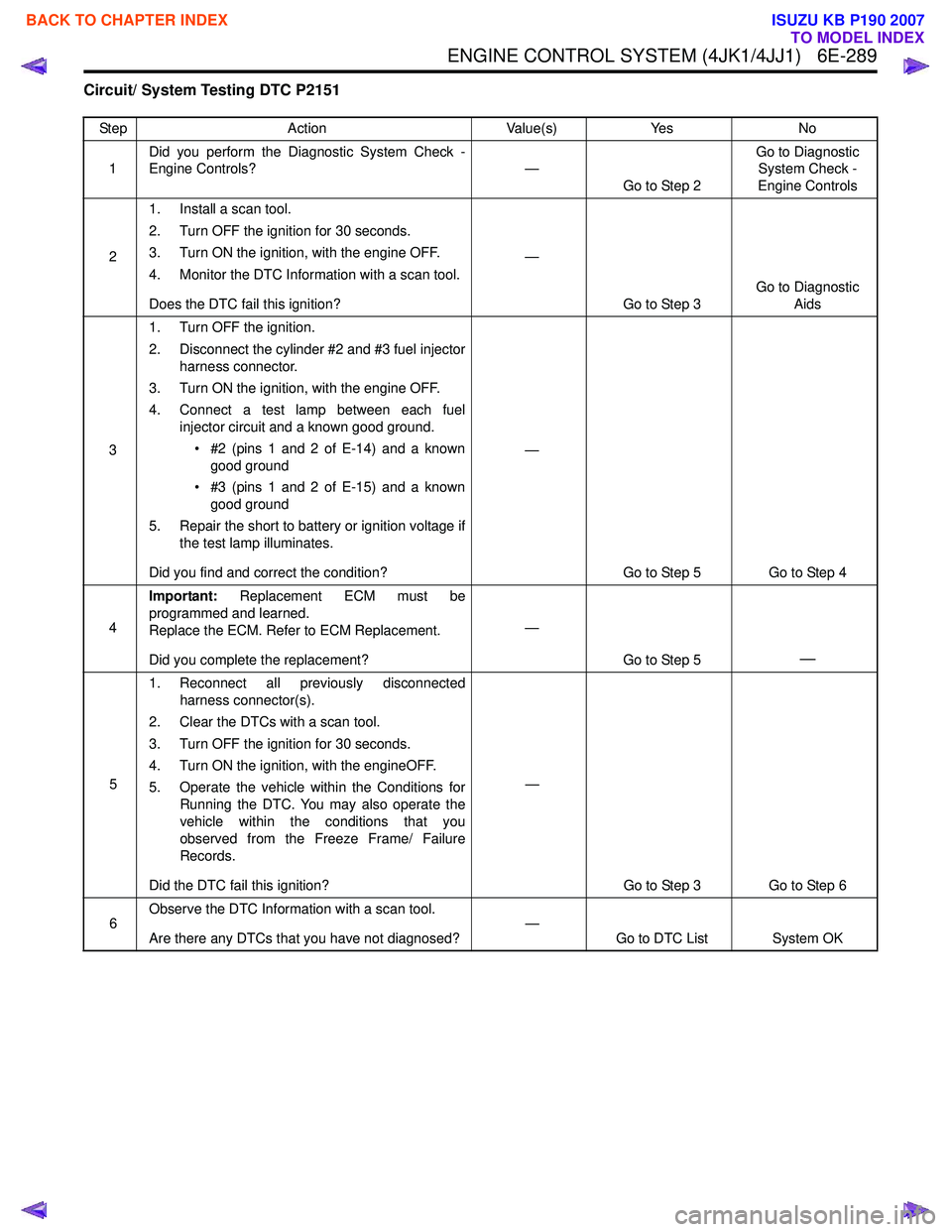
Circuit/ System Testing DTC P2151
StepAction Value(s)Yes No
1 Did you perform the Diagnostic System Check -
Engine Controls? —
Go to Step 2 Go to Diagnostic
System Check -
Engine Controls
2 1. Install a scan tool.
2. Turn OFF the ignition for 30 seconds.
3. Turn ON the ignition, with the engine OFF.
4. Monitor the DTC Information with a scan tool.
Does the DTC fail this ignition? —
Go to Step 3 Go to Diagnostic
Aids
3 1. Turn OFF the ignition.
2. Disconnect the cylinder #2 and #3 fuel injector harness connector.
3. Turn ON the ignition, with the engine OFF.
4. Connect a test lamp between each fuel injector circuit and a known good ground.
• #2 (pins 1 and 2 of E-14) and a known good ground
• #3 (pins 1 and 2 of E-15) and a known good ground
5. Repair the short to battery or ignition voltage if the test lamp illuminates.
Did you find and correct the condition? —
Go to Step 5 Go to Step 4
4 Important:
Replacement ECM must be
programmed and learned.
Replace the ECM. Refer to ECM Replacement.
Did you complete the replacement? —
Go to Step 5
—
51. Reconnect all previously disconnected
harness connector(s).
2. Clear the DTCs with a scan tool.
3. Turn OFF the ignition for 30 seconds.
4. Turn ON the ignition, with the engineOFF.
5. Operate the vehicle within the Conditions for Running the DTC. You may also operate the
vehicle within the conditions that you
observed from the Freeze Frame/ Failure
Records.
Did the DTC fail this ignition? —
Go to Step 3 Go to Step 6
6 Observe the DTC Information with a scan tool.
Are there any DTCs that you have not diagnosed? —
Go to DTC List System OK
BACK TO CHAPTER INDEX
TO MODEL INDEX
ISUZU KB P190 2007
Page 1907 of 6020
6E-290 ENGINE CONTROL SYSTEM (4JK1/4JJ1)
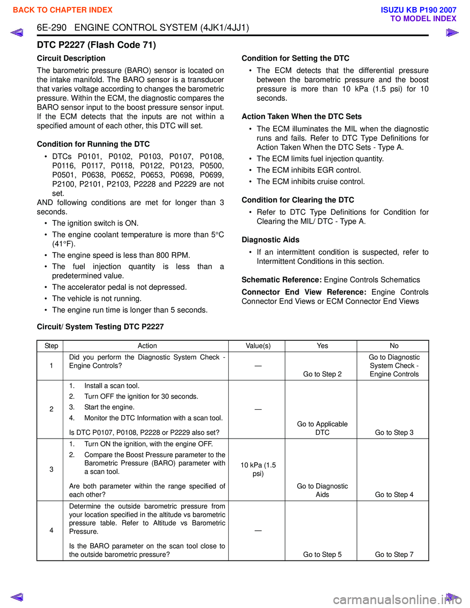
DTC P2227 (Flash Code 71)
Circuit Description
The barometric pressure (BARO) sensor is located on
the intake manifold. The BARO sensor is a transducer
that varies voltage according to changes the barometric
pressure. Within the ECM, the diagnostic compares the
BARO sensor input to the boost pressure sensor input.
If the ECM detects that the inputs are not within a
specified amount of each other, this DTC will set.
Condition for Running the DTC • DTCs P0101, P0102, P0103, P0107, P0108, P0116, P0117, P0118, P0122, P0123, P0500,
P0501, P0638, P0652, P0653, P0698, P0699,
P2100, P2101, P2103, P2228 and P2229 are not
set.
AND following conditions are met for longer than 3
seconds.
• The ignition switch is ON.
• The engine coolant temperature is more than 5 °C
(41 °F).
• The engine speed is less than 800 RPM.
• The fuel injection quantity is less than a predetermined value.
• The accelerator pedal is not depressed.
• The vehicle is not running.
• The engine run time is longer than 5 seconds. Condition for Setting the DTC
• The ECM detects that the differential pressure between the barometric pressure and the boost
pressure is more than 10 kPa (1.5 psi) for 10
seconds.
Action Taken When the DTC Sets • The ECM illuminates the MIL when the diagnostic runs and fails. Refer to DTC Type Definitions for
Action Taken When the DTC Sets - Type A.
• The ECM limits fuel injection quantity.
• The ECM inhibits EGR control.
• The ECM inhibits cruise control.
Condition for Clearing the DTC • Refer to DTC Type Definitions for Condition for Clearing the MIL/ DTC - Type A.
Diagnostic Aids • If an intermittent condition is suspected, refer to Intermittent Conditions in this section.
Schematic Reference: Engine Controls Schematics
Connector End View Reference: Engine Controls
Connector End Views or ECM Connector End Views
Circuit/ System Testing DTC P2227
Step Action Value(s)Yes No
1 Did you perform the Diagnostic System Check -
Engine Controls? —
Go to Step 2 Go to Diagnostic
System Check -
Engine Controls
2 1. Install a scan tool.
2. Turn OFF the ignition for 30 seconds.
3. Start the engine.
4. Monitor the DTC Information with a scan tool.
Is DTC P0107, P0108, P2228 or P2229 also set? —
Go to Applicable DTC Go to Step 3
3 1. Turn ON the ignition, with the engine OFF.
2. Compare the Boost Pressure parameter to the Barometric Pressure (BARO) parameter with
a scan tool.
Are both parameter within the range specified of
each other? 10 kPa (1.5
psi)
Go to Diagnostic Aids Go to Step 4
4 Determine the outside barometric pressure from
your location specified in the altitude vs barometric
pressure table. Refer to Altitude vs Barometric
Pressure.
Is the BARO parameter on the scan tool close to
the outside barometric pressure? —
Go to Step 5 Go to Step 7
BACK TO CHAPTER INDEX
TO MODEL INDEX
ISUZU KB P190 2007
Page 1908 of 6020
ENGINE CONTROL SYSTEM (4JK1/4JJ1) 6E-291
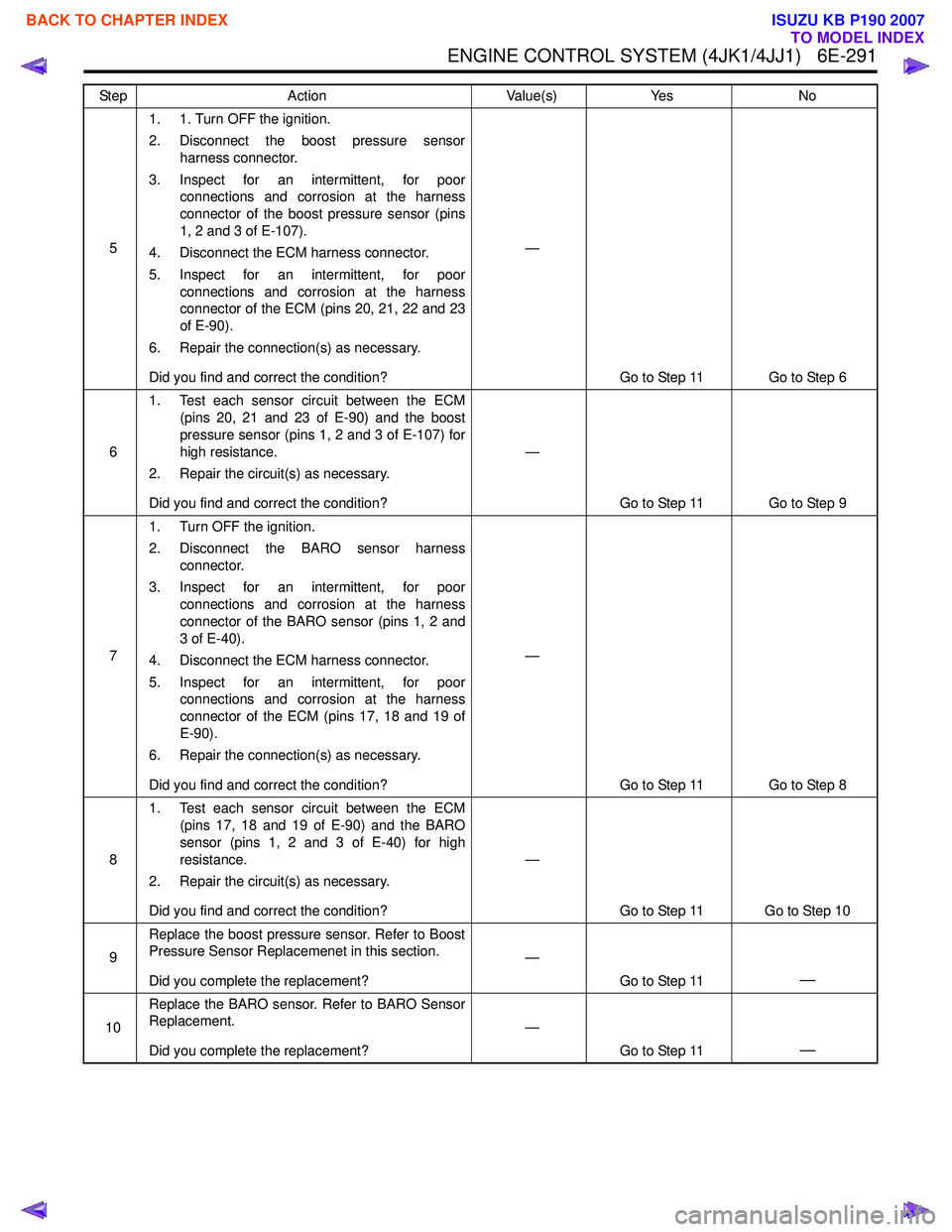
51. 1. Turn OFF the ignition.
2. Disconnect the boost pressure sensor harness connector.
3. Inspect for an intermittent, for poor connections and corrosion at the harness
connector of the boost pressure sensor (pins
1, 2 and 3 of E-107).
4. Disconnect the ECM harness connector.
5. Inspect for an intermittent, for poor connections and corrosion at the harness
connector of the ECM (pins 20, 21, 22 and 23
of E-90).
6. Repair the connection(s) as necessary.
Did you find and correct the condition? —
Go to Step 11 Go to Step 6
6 1. Test each sensor circuit between the ECM
(pins 20, 21 and 23 of E-90) and the boost
pressure sensor (pins 1, 2 and 3 of E-107) for
high resistance.
2. Repair the circuit(s) as necessary.
Did you find and correct the condition? —
Go to Step 11 Go to Step 9
7 1. Turn OFF the ignition.
2. Disconnect the BARO sensor harness connector.
3. Inspect for an intermittent, for poor connections and corrosion at the harness
connector of the BARO sensor (pins 1, 2 and
3 of E-40).
4. Disconnect the ECM harness connector.
5. Inspect for an intermittent, for poor connections and corrosion at the harness
connector of the ECM (pins 17, 18 and 19 of
E-90).
6. Repair the connection(s) as necessary.
Did you find and correct the condition? —
Go to Step 11 Go to Step 8
8 1. Test each sensor circuit between the ECM
(pins 17, 18 and 19 of E-90) and the BARO
sensor (pins 1, 2 and 3 of E-40) for high
resistance.
2. Repair the circuit(s) as necessary.
Did you find and correct the condition? —
Go to Step 11 Go to Step 10
9 Replace the boost pressure sensor. Refer to Boost
Pressure Sensor Replacemenet in this section.
Did you complete the replacement? —
Go to Step 11
—
10Replace the BARO sensor. Refer to BARO Sensor
Replacement.
Did you complete the replacement? —
Go to Step 11
—
Step Action Value(s)Yes No
BACK TO CHAPTER INDEX
TO MODEL INDEX
ISUZU KB P190 2007
Page 1909 of 6020
6E-292 ENGINE CONTROL SYSTEM (4JK1/4JJ1)
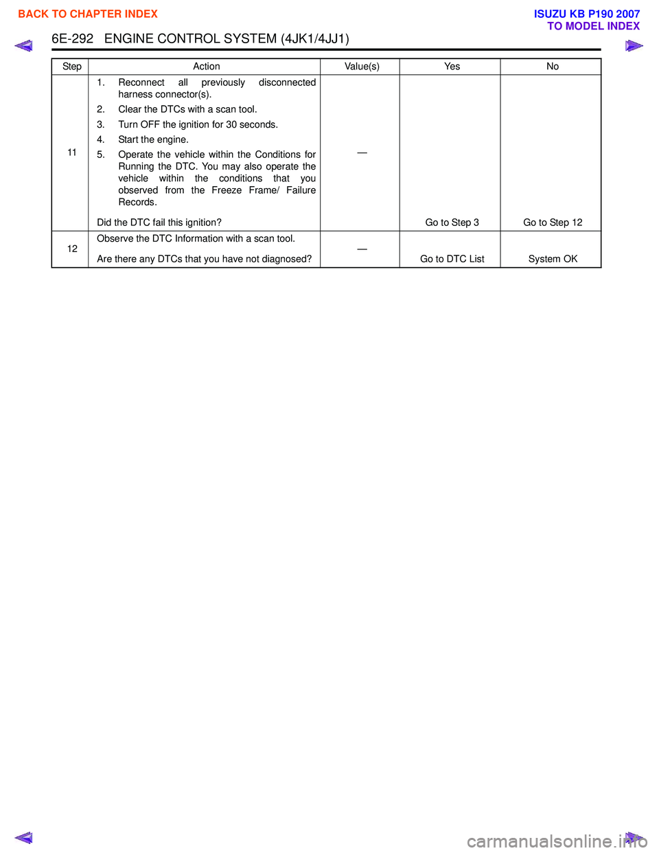
111. Reconnect all previously disconnected
harness connector(s).
2. Clear the DTCs with a scan tool.
3. Turn OFF the ignition for 30 seconds.
4. Start the engine.
5. Operate the vehicle within the Conditions for Running the DTC. You may also operate the
vehicle within the conditions that you
observed from the Freeze Frame/ Failure
Records.
Did the DTC fail this ignition? —
Go to Step 3 Go to Step 12
12 Observe the DTC Information with a scan tool.
Are there any DTCs that you have not diagnosed? —
Go to DTC List System OK
Step
Action Value(s)Yes No
BACK TO CHAPTER INDEX
TO MODEL INDEX
ISUZU KB P190 2007
Page 1910 of 6020
ENGINE CONTROL SYSTEM (4JK1/4JJ1) 6E-293
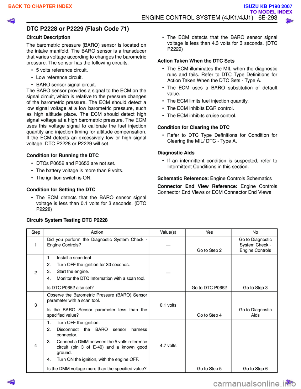
DTC P2228 or P2229 (Flash Code 71)
Circuit Description
The barometric pressure (BARO) sensor is located on
the intake manifold. The BARO sensor is a transducer
that varies voltage according to changes the barometric
pressure. The sensor has the following circuits.
• 5 volts reference circuit.
• Low reference circuit.
• BARO sensor signal circuit.
The BARO sensor provides a signal to the ECM on the
signal circuit, which is relative to the pressure changes
of the barometric pressure. The ECM should detect a
low signal voltage at a low barometric pressure, such
as high altitude place. The ECM should detect high
signal voltage at a high barometric pressure. The ECM
uses this voltage signal to calibrate the fuel injection
quantity and injection timing for altitude compensation.
If the ECM detects an excessively low or high signal
voltage, DTC P2228 or P2229 will set.
Condition for Running the DTC • DTCs P0652 and P0653 are not set.
• The battery voltage is more than 9 volts.
• The ignition switch is ON.
Condition for Setting the DTC • The ECM detects that the BARO sensor signal voltage is less than 0.1 volts for 3 seconds. (DTC
P2228) • The ECM detects that the BARO sensor signal
voltage is less than 4.3 volts for 3 seconds. (DTC
P2229)
Action Taken When the DTC Sets • The ECM illuminates the MIL when the diagnostic runs and fails. Refer to DTC Type Definitions for
Action Taken When the DTC Sets - Type A.
• The ECM uses a BARO substitution of default value.
• The ECM limits fuel injection quantity.
• The ECM inhibits EGR control.
• The ECM inhibits cruise control.
Condition for Clearing the DTC • Refer to DTC Type Definitions for Condition for Clearing the MIL/ DTC - Type A.
Diagnostic Aids • If an intermittent condition is suspected, refer to Intermittent Conditions in this section.
Schematic Reference: Engine Controls Schematics
Connector End View Reference: Engine Controls
Connector End Views or ECM Connector End Views
Circuit/ System Testing DTC P2228
Step Action Value(s)Yes No
1 Did you perform the Diagnostic System Check -
Engine Controls? —
Go to Step 2 Go to Diagnostic
System Check -
Engine Controls
2 1. Install a scan tool.
2. Turn OFF the ignition for 30 seconds.
3. Start the engine.
4. Monitor the DTC Information with a scan tool.
Is DTC P0652 also set? —
Go to DTC P0652 Go to Step 3
3 Observe the Barometric Pressure (BARO) Sensor
parameter with a scan tool.
Is the BARO Sensor parameter less than the
specified value? 0.1 volts
Go to Step 4 Go to Diagnostic
Aids
4 1. Turn OFF the ignition.
2. Disconnect the BARO sensor harness connector.
3. Connect a DMM between the 5 volts reference circuit (pin 3 of E-40) and a known good
ground.
4. Turn ON the ignition, with the engine OFF.
Is the DMM voltage more than the specified value? 4.7 volts
Go to Step 5 Go to Step 6
BACK TO CHAPTER INDEX
TO MODEL INDEX
ISUZU KB P190 2007
Page 1911 of 6020
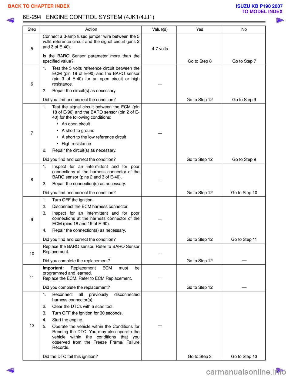
6E-294 ENGINE CONTROL SYSTEM (4JK1/4JJ1)
5Connect a 3-amp fused jumper wire between the 5
volts reference circuit and the signal circuit (pins 2
and 3 of E-40).
Is the BARO Sensor parameter more than the
specified value? 4.7 volts
Go to Step 8 Go to Step 7
6 1. Test the 5 volts reference circuit between the
ECM (pin 19 of E-90) and the BARO sensor
(pin 3 of E-40) for an open circuit or high
resistance.
2. Repair the circuit(s) as necessary.
Did you find and correct the condition? —
Go to Step 12 Go to Step 9
7 1. Test the signal circuit between the ECM (pin
18 of E-90) and the BARO sensor (pin 2 of E-
40) for the following conditions:
• An open circuit
• A short to ground
• A short to the low reference circuit
• High resistance
2. Repair the circuit(s) as necessary.
Did you find and correct the condition? —
Go to Step 12 Go to Step 9
8 1. Inspect for an intermittent and for poor
connections at the harness connector of the
BARO sensor (pins 2 and 3 of E-40).
2. Repair the connection(s) as necessary.
Did you find and correct the condition? —
Go to Step 12 Go to Step 10
9 1. Turn OFF the ignition.
2. Disconnect the ECM harness connector.
3. Inspect for an intermittent and for poor connections at the harness connector of the
ECM (pins 18 and 19 of E-90).
4. Repair the connection(s) as necessary.
Did you find and correct the condition? —
Go to Step 12 Go to Step 11
10 Replace the BARO sensor. Refer to BARO Sensor
Replacement.
Did you complete the replacement? —
Go to Step 12
—
11Important:
Replacement ECM must be
programmed and learned.
Replace the ECM. Refer to ECM Replacement.
Did you complete the replacement? —
Go to Step 12
—
121. Reconnect all previously disconnected
harness connector(s).
2. Clear the DTCs with a scan tool.
3. Turn OFF the ignition for 30 seconds.
4. Start the engine.
5. Operate the vehicle within the Conditions for Running the DTC. You may also operate the
vehicle within the conditions that you
observed from the Freeze Frame/ Failure
Records.
Did the DTC fail this ignition? —
Go to Step 3 Go to Step 13
Step
Action Value(s)Yes No
BACK TO CHAPTER INDEX
TO MODEL INDEX
ISUZU KB P190 2007
Page 1912 of 6020
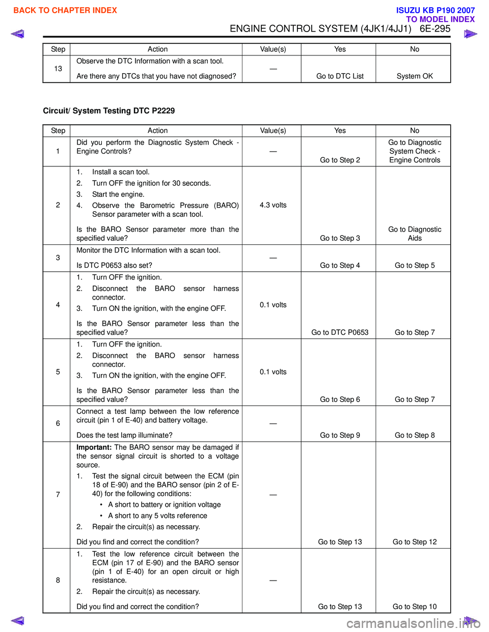
ENGINE CONTROL SYSTEM (4JK1/4JJ1) 6E-295
Circuit/ System Testing DTC P2229
13Observe the DTC Information with a scan tool.
Are there any DTCs that you have not diagnosed? —
Go to DTC List System OK
Step Action Value(s) Yes No
Step
Action Value(s)Yes No
1 Did you perform the Diagnostic System Check -
Engine Controls? —
Go to Step 2 Go to Diagnostic
System Check -
Engine Controls
2 1. Install a scan tool.
2. Turn OFF the ignition for 30 seconds.
3. Start the engine.
4. Observe the Barometric Pressure (BARO) Sensor parameter with a scan tool.
Is the BARO Sensor parameter more than the
specified value? 4.3 volts
Go to Step 3 Go to Diagnostic
Aids
3 Monitor the DTC Information with a scan tool.
Is DTC P0653 also set? —
Go to Step 4 Go to Step 5
4 1. Turn OFF the ignition.
2. Disconnect the BARO sensor harness connector.
3. Turn ON the ignition, with the engine OFF.
Is the BARO Sensor parameter less than the
specified value? 0.1 volts
Go to DTC P0653 Go to Step 7
5 1. Turn OFF the ignition.
2. Disconnect the BARO sensor harness connector.
3. Turn ON the ignition, with the engine OFF.
Is the BARO Sensor parameter less than the
specified value? 0.1 volts
Go to Step 6 Go to Step 7
6 Connect a test lamp between the low reference
circuit (pin 1 of E-40) and battery voltage.
Does the test lamp illuminate? —
Go to Step 9 Go to Step 8
7 Important:
The BARO sensor may be damaged if
the sensor signal circuit is shorted to a voltage
source.
1. Test the signal circuit between the ECM (pin 18 of E-90) and the BARO sensor (pin 2 of E-
40) for the following conditions:
• A short to battery or ignition voltage
• A short to any 5 volts reference
2. Repair the circuit(s) as necessary.
Did you find and correct the condition? —
Go to Step 13 Go to Step 12
8 1. Test the low reference circuit between the
ECM (pin 17 of E-90) and the BARO sensor
(pin 1 of E-40) for an open circuit or high
resistance.
2. Repair the circuit(s) as necessary.
Did you find and correct the condition? —
Go to Step 13 Go to Step 10
BACK TO CHAPTER INDEX
TO MODEL INDEX
ISUZU KB P190 2007
Page 1913 of 6020
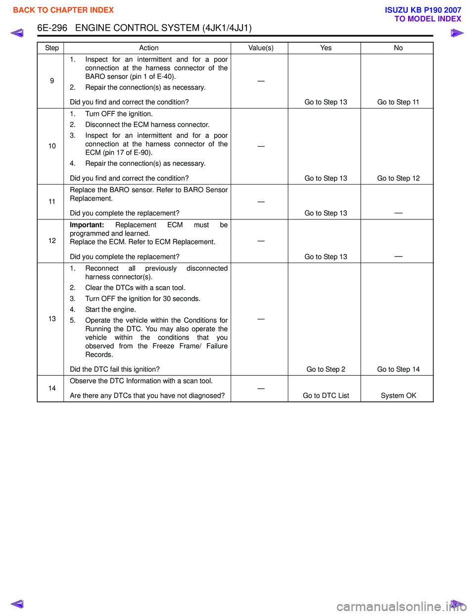
6E-296 ENGINE CONTROL SYSTEM (4JK1/4JJ1)
91. Inspect for an intermittent and for a poor
connection at the harness connector of the
BARO sensor (pin 1 of E-40).
2. Repair the connection(s) as necessary.
Did you find and correct the condition? —
Go to Step 13 Go to Step 11
10 1. Turn OFF the ignition.
2. Disconnect the ECM harness connector.
3. Inspect for an intermittent and for a poor connection at the harness connector of the
ECM (pin 17 of E-90).
4. Repair the connection(s) as necessary.
Did you find and correct the condition? —
Go to Step 13 Go to Step 12
11 Replace the BARO sensor. Refer to BARO Sensor
Replacement.
Did you complete the replacement? —
Go to Step 13
—
12Important:
Replacement ECM must be
programmed and learned.
Replace the ECM. Refer to ECM Replacement.
Did you complete the replacement? —
Go to Step 13
—
131. Reconnect all previously disconnected
harness connector(s).
2. Clear the DTCs with a scan tool.
3. Turn OFF the ignition for 30 seconds.
4. Start the engine.
5. Operate the vehicle within the Conditions for Running the DTC. You may also operate the
vehicle within the conditions that you
observed from the Freeze Frame/ Failure
Records.
Did the DTC fail this ignition? —
Go to Step 2 Go to Step 14
14 Observe the DTC Information with a scan tool.
Are there any DTCs that you have not diagnosed? —
Go to DTC List System OK
Step
Action Value(s)Yes No
BACK TO CHAPTER INDEX
TO MODEL INDEX
ISUZU KB P190 2007