2007 ISUZU KB P190 ignition
[x] Cancel search: ignitionPage 3737 of 6020
Powertrain Interface Module – V6 Page 6E1–76
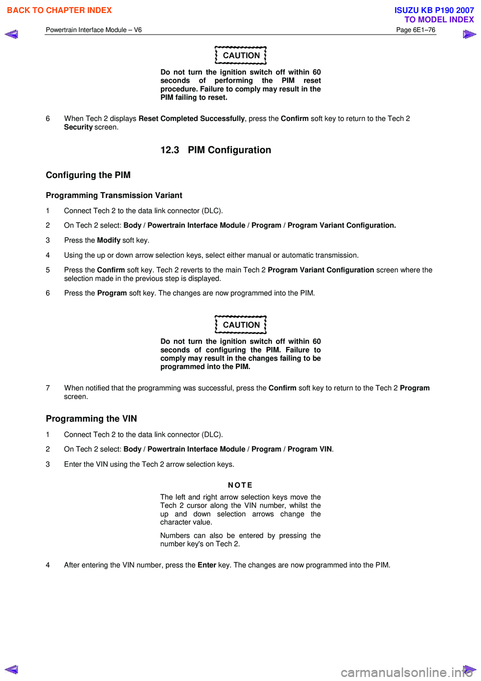
Do not turn the ignition switch off within 60
seconds of performing the PIM reset
procedure. Failure to comply may result in the
PIM failing to reset.
6 W hen Tech 2 displays Reset Completed Successfully , press the Confirm soft key to return to the Tech 2
Security screen.
12.3 PIM Configuration
Configuring the PIM
Programming Transmission Variant
1 Connect Tech 2 to the data link connector (DLC).
2 On Tech 2 select: Body / Powertrain Interface Module / Program / Program Variant Configuration.
3 Press the Modify soft key.
4 Using the up or down arrow selection keys, select either manual or automatic transmission.
5 Press the Confirm soft key. Tech 2 reverts to the main Tech 2 Program Variant Configuration screen where the
selection made in the previous step is displayed.
6 Press the Program soft key. The changes are now programmed into the PIM.
Do not turn the ignition switch off within 60
seconds of configuring the PIM. Failure to
comply may result in the changes failing to be
programmed into the PIM.
7 W hen notified that the programming was successful, press the Confirm soft key to return to the Tech 2 Program
screen.
Programming the VIN
1 Connect Tech 2 to the data link connector (DLC).
2 On Tech 2 select: Body / Powertrain Interface Module / Program / Program VIN .
3 Enter the VIN using the Tech 2 arrow selection keys.
NOTE
The left and right arrow selection keys move the
Tech 2 cursor along the VIN number, whilst the
up and down selection arrows change the
character value.
Numbers can also be entered by pressing the
number key's on Tech 2.
4 After entering the VIN number, press the Enter key. The changes are now programmed into the PIM.
BACK TO CHAPTER INDEX
TO MODEL INDEX
ISUZU KB P190 2007
Page 3738 of 6020
Powertrain Interface Module – V6 Page 6E1–77
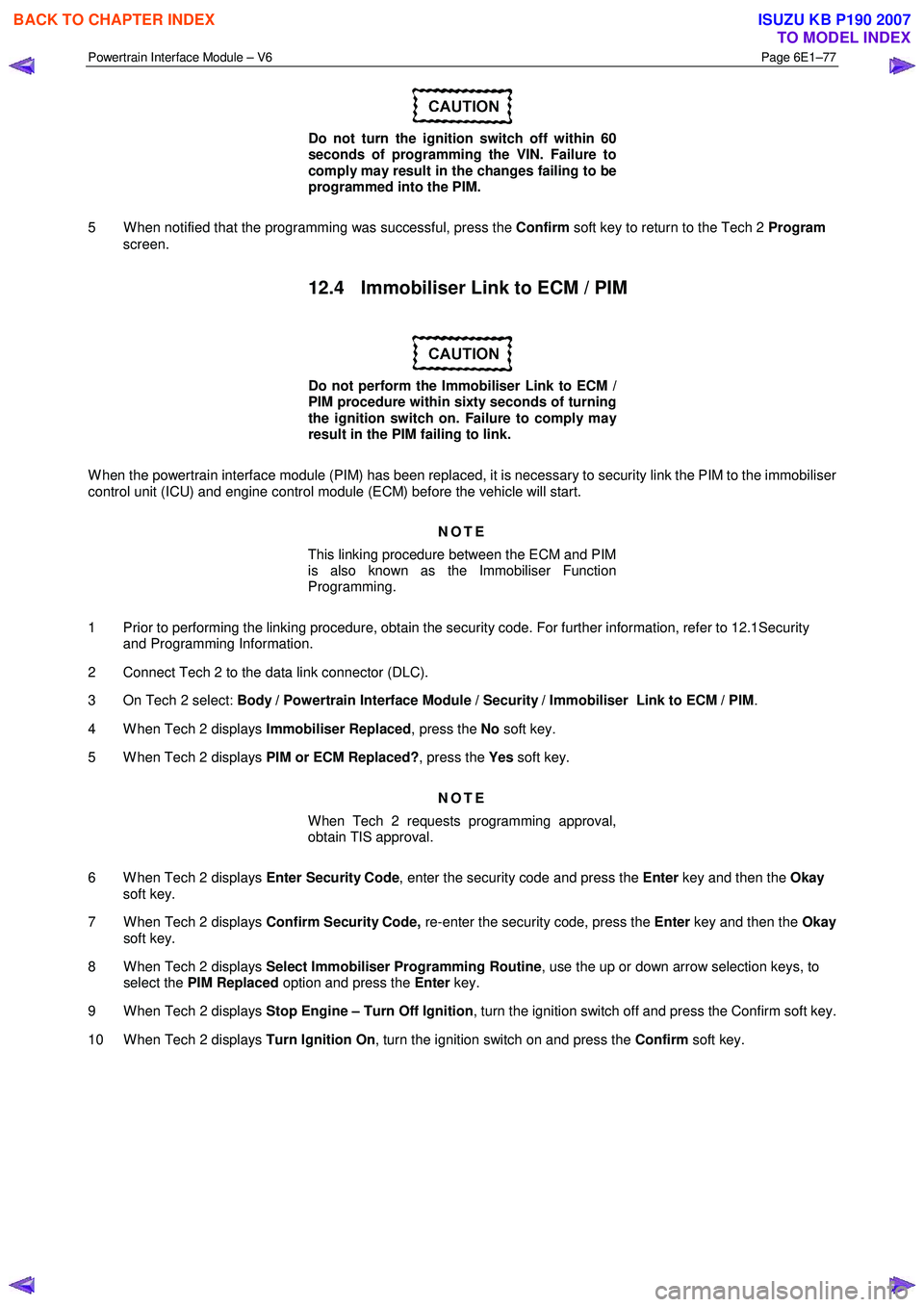
Do not turn the ignition switch off within 60
seconds of programming the VIN. Failure to
comply may result in the changes failing to be
programmed into the PIM.
5 W hen notified that the programming was successful, press the Confirm soft key to return to the Tech 2 Program
screen.
12.4 Immobiliser Link to ECM / PIM
Do not perform the Immobiliser Link to ECM /
PIM procedure within sixty seconds of turning
the ignition switch on. Failure to comply may
result in the PIM failing to link.
W hen the powertrain interface module (PIM) has been replaced, it is necessary to security link the PIM to the immobiliser
control unit (ICU) and engine control module (ECM) before the vehicle will start.
NOTE
This linking procedure between the ECM and PIM
is also known as the Immobiliser Function
Programming.
1 Prior to performing the linking procedure, obtain the security code. For further information, refer to 12.1Security and Programming Information.
2 Connect Tech 2 to the data link connector (DLC).
3 On Tech 2 select: Body / Powertrain Interface Module / Security / Immobiliser Link to ECM / PIM .
4 W hen Tech 2 displays Immobiliser Replaced, press the No soft key.
5 W hen Tech 2 displays PIM or ECM Replaced?, press the Yes soft key.
NOTE
When Tech 2 requests programming approval,
obtain TIS approval.
6 W hen Tech 2 displays Enter Security Code, enter the security code and press the Enter key and then the Okay
soft key.
7 W hen Tech 2 displays Confirm Security Code, re-enter the security code, press the Enter key and then the Okay
soft key.
8 W hen Tech 2 displays Select Immobiliser Programming Routine , use the up or down arrow selection keys, to
select the PIM Replaced option and press the Enter key.
9 W hen Tech 2 displays Stop Engine – Turn Off Ignition , turn the ignition switch off and press the Confirm soft key.
10 W hen Tech 2 displays Turn Ignition On, turn the ignition switch on and press the Confirm soft key.
BACK TO CHAPTER INDEX
TO MODEL INDEX
ISUZU KB P190 2007
Page 3739 of 6020
Powertrain Interface Module – V6 Page 6E1–78
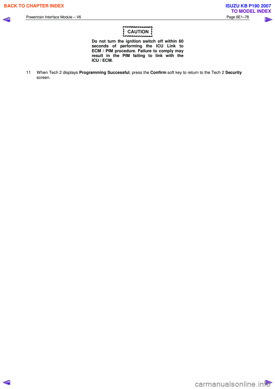
Do not turn the ignition switch off within 60
seconds of performing the ICU Link to
ECM / PIM procedure. Failure to comply may
result in the PIM failing to link with the
ICU / ECM.
11 W hen Tech 2 displays Programming Successful, press the Confirm soft key to return to the Tech 2 Security
screen.
BACK TO CHAPTER INDEX
TO MODEL INDEX
ISUZU KB P190 2007
Page 3744 of 6020
Powertrain Interface Module – V6 Page 6E1–83
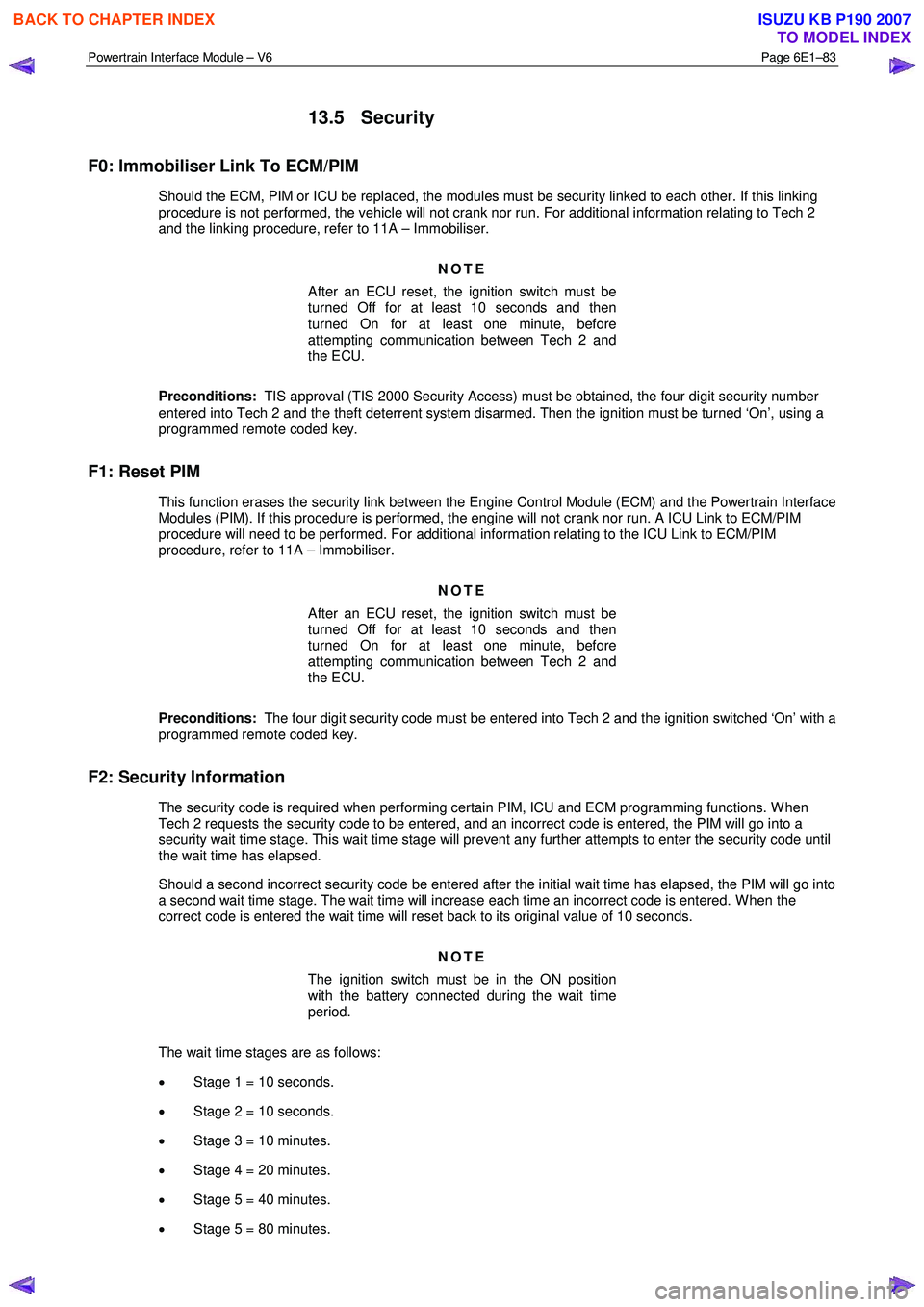
13.5 Security
F0: Immobiliser Link To ECM/PIM
Should the ECM, PIM or ICU be replaced, the modules must be security linked to each other. If this linking
procedure is not performed, the vehicle will not crank nor run. For additional information relating to Tech 2
and the linking procedure, refer to 11A – Immobiliser.
NOTE
After an ECU reset, the ignition switch must be
turned Off for at least 10 seconds and then
turned On for at least one minute, before
attempting communication between Tech 2 and
the ECU.
Preconditions: TIS approval (TIS 2000 Security Access) must be obtained, the four digit security number
entered into Tech 2 and the theft deterrent system disarmed. Then the ignition must be turned ‘On’, using a
programmed remote coded key.
F1: Reset PIM
This function erases the security link between the Engine Control Module (ECM) and the Powertrain Interface Modules (PIM). If this procedure is performed, the engine will not crank nor run. A ICU Link to ECM/PIM
procedure will need to be performed. For additional information relating to the ICU Link to ECM/PIM
procedure, refer to 11A – Immobiliser.
NOTE
After an ECU reset, the ignition switch must be
turned Off for at least 10 seconds and then
turned On for at least one minute, before
attempting communication between Tech 2 and
the ECU.
Preconditions: The four digit security code must be entered into Tech 2 and the ignition switched ‘On’ with a
programmed remote coded key.
F2: Security Information
The security code is required when performing certain PIM, ICU and ECM programming functions. W hen Tech 2 requests the security code to be entered, and an incorrect code is entered, the PIM will go into a
security wait time stage. This wait time stage will prevent any further attempts to enter the security code until
the wait time has elapsed.
Should a second incorrect security code be entered after the initial wait time has elapsed, the PIM will go into a second wait time stage. The wait time will increase each time an incorrect code is entered. W hen the
correct code is entered the wait time will reset back to its original value of 10 seconds.
NOTE
The ignition switch must be in the ON position
with the battery connected during the wait time
period.
The wait time stages are as follows: • Stage 1 = 10 seconds.
• Stage 2 = 10 seconds.
• Stage 3 = 10 minutes.
• Stage 4 = 20 minutes.
• Stage 5 = 40 minutes.
• Stage 5 = 80 minutes.
BACK TO CHAPTER INDEX
TO MODEL INDEX
ISUZU KB P190 2007
Page 3745 of 6020
Powertrain Interface Module – V6 Page 6E1–84
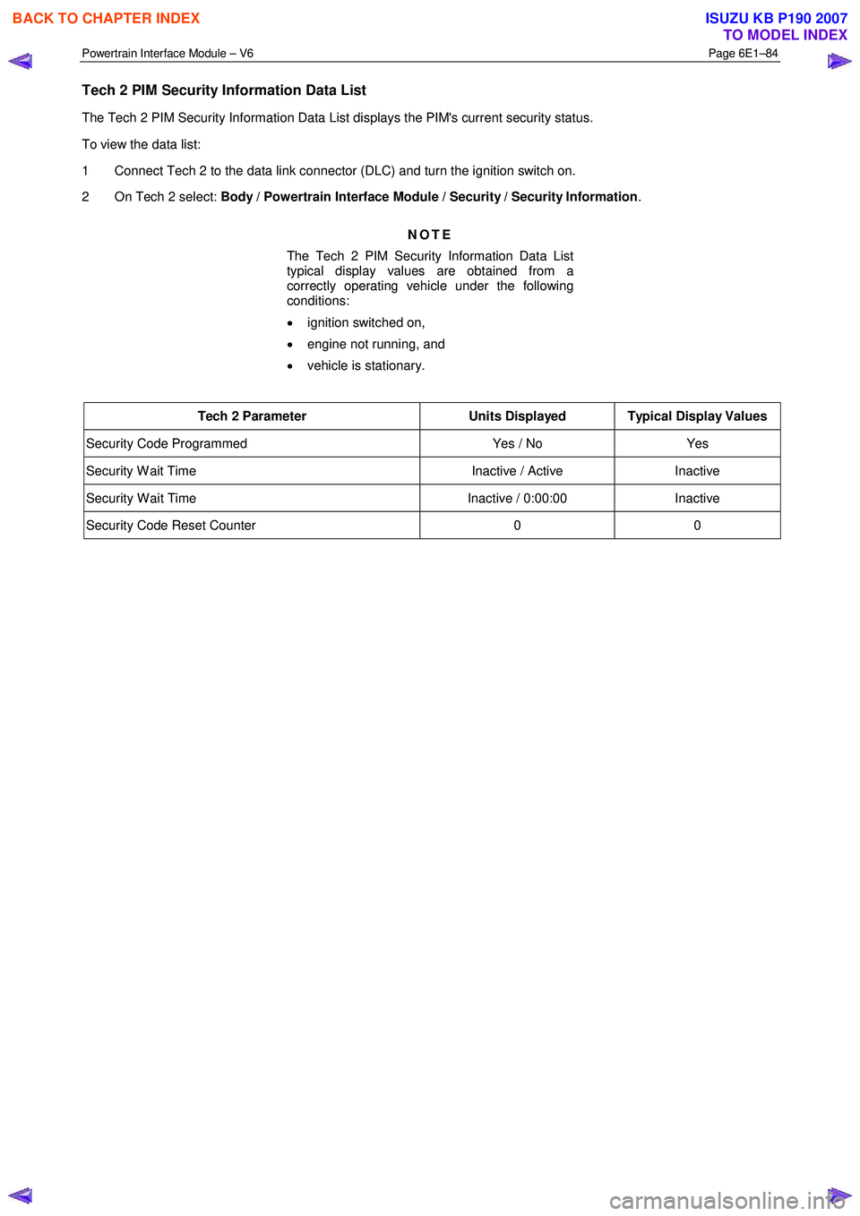
Tech 2 PIM Security Information Data List
The Tech 2 PIM Security Information Data List displays the PIM's current security status.
To view the data list:
1 Connect Tech 2 to the data link connector (DLC) and turn the ignition switch on.
2 On Tech 2 select: Body / Powertrain Interface Module / Security / Security Information .
NOTE
The Tech 2 PIM Security Information Data List
typical display values are obtained from a
correctly operating vehicle under the following
conditions:
• ignition switched on,
• engine not running, and
• vehicle is stationary.
Tech 2 Parameter Units Displayed Typical Display Values
Security Code Programmed Yes / No Yes
Security W ait Time Inactive / Active Inactive
Security W ait Time Inactive / 0:00:00 Inactive
Security Code Reset Counter 0 0
BACK TO CHAPTER INDEX
TO MODEL INDEX
ISUZU KB P190 2007
Page 3753 of 6020
Exhaust System – V6 Page 6F – 5
Service Notes
1. Vehicles fitted with catalytic converters should not be operated with leaded petrol. Lead will contaminate
the ceramic monolith.
2. Do not drop the catalytic converter as it will damage the ceramic monolith.
3. Replace the catalytic converter if it is damaged.
4. Do not allow water, oil or fuel to enter the converter as the ceramic monolith will be contaminated.
5. Do not use engine and/or fuel additives unless approved by General Motors. Many additives contain phosphorous that will contaminate the ceramic monolith.
6. The vehicle must not be started by pushing or towing, as unburned fuel could reach the catalytic converter and destroy the ceramic monolith. Always use jumper leads to start a vehicle that has a flat or
defective battery.
7. W hen carrying out a compression test, for V6 engines use Tech 2 to ensure the output control Engine Compression Test is set to enable, refer to 6A1 Engine Mechanical. This prevents fuel injection and
ignition during engine cranking.
8. Do not drive the vehicle with the engine misfiring or with any of the spark plug leads disconnected, as the catalytic converter will overheat.
9. Do not coast downhill with the engine misfiring or with any of the spark plug leads disconnected.
10. The catalytic converter is serviceable as part of the front exhaust assembly only. Refer to the service operations in this section for details of front exhaust pipe assembly removal and reinstallation.
11. The exhaust flange gaskets must be replaced whenever a new exhaust pipe, muffler or catalytic converter is installed.
1.3 WARNING, CAUTION and NOTES
This Section contains various W ARNINGS, CAUTIONS and NOTE statements that you must observe carefully to reduce
the risk of death or injury during service, repair procedures or vehicle operation. Incorrect service or repair procedures
may damage the vehicle or cause operational faults. W ARNINGS, CAUTION and NOTE statements are not exhaustive.
HOLDEN LTD can not possibly warn of all the potentially hazardous consequences of failure to follow these instructions.
1.1 Definition of WARNING, CAUTION and NOTE Statements
Diagnosis and repair procedures in this Section contain both general and specific W ARNING, CAUTION and NOTE
statements. HOLDEN LTD is dedicated to the presentation of service information that helps the technician to diagnose
and repair the systems necessary for proper operation of the vehicle. Certain procedures may present a hazard to the
technician if they are not followed in the recommended manner. W ARNING, CAUTION and NOTE statements are
designed to help prevent these hazards from occurring, but not all hazards can be foreseen.
WARNING defined
A W ARNING statement immediately precedes an operating procedure or maintenance practice which, if not correctly
followed, could result in death or injury. A W ARNING statement alerts you to take necessary action or not to take a
prohibited action. If a W ARNING statement is ignored, the following consequences may occur:
• Death or injury to the technician or other personnel working on the vehicle,
• Death or injury to other people in or near the workplace area, and / or
• Death or injury to the driver / or passenger(s) of the vehicle or other people, if the vehicle has been improperly
repaired.
CAUTION defined
A CAUTION statement immediately precedes an operating procedure or maintenance practice which, if not correctly
followed, could result in damage to or destruction of equipment, or corruption of data. If a CAUTION statement is
ignored, the following consequences may occur:
• Damage to the vehicle,
• Unnecessary vehicle repairs or component replacement,
BACK TO CHAPTER INDEX
TO MODEL INDEX
ISUZU KB P190 2007
Page 3796 of 6020
Automatic Transmission – 4L60E – Electrical Diagnosis Page 7C2–10
Limp Home Mode Description
If a major electrical system failure occurs which could affect vehicle safety or damage the transmission during normal
operation, the TCM enters a limp home mode. In the limp home mode, the transmission operates in the following
manner:
• The pressure control solenoid is off and the line pressure is at maximum to minimise clutch slippage.
• The TCC solenoid is off, therefore the torque converter clutch is disabled.
• The two shift solenoids are turned off. The transmission will operate in fourth gear if the vehicle has successfully
completed a 1-2 upshift in the current ignition cycle. If the vehicle has not completed a 1-2 upshift in the current
ignition cycle, the transmission will operate in third gear. If the transmission is operating in fourth gear, third gear
may be obtained if the engine is stopped briefly and re-started.
In limp home mode, the gear selector lever is ineffective at selecting forward gear ranges. In third or fourth gear, heat
builds up in the transmission quickly, particularly in stop and go traffic. Excessive heat build-up may cause transmission
failure if the vehicle is driven for extended distances in limp home mode.
1.3 Transmission Indicators and Messages
For information pertaining to the instrument cluster and the transmission information it displays, refer to the RA Rodeo
Owner Handbook.
1.4 Electronic Component Description
For all other electrical components not covered in this section, refer to General Motors Powertrain Group Electronically
Controlled Automatic Transmission Technician's Guide.
Transmission Control Module (TCM)
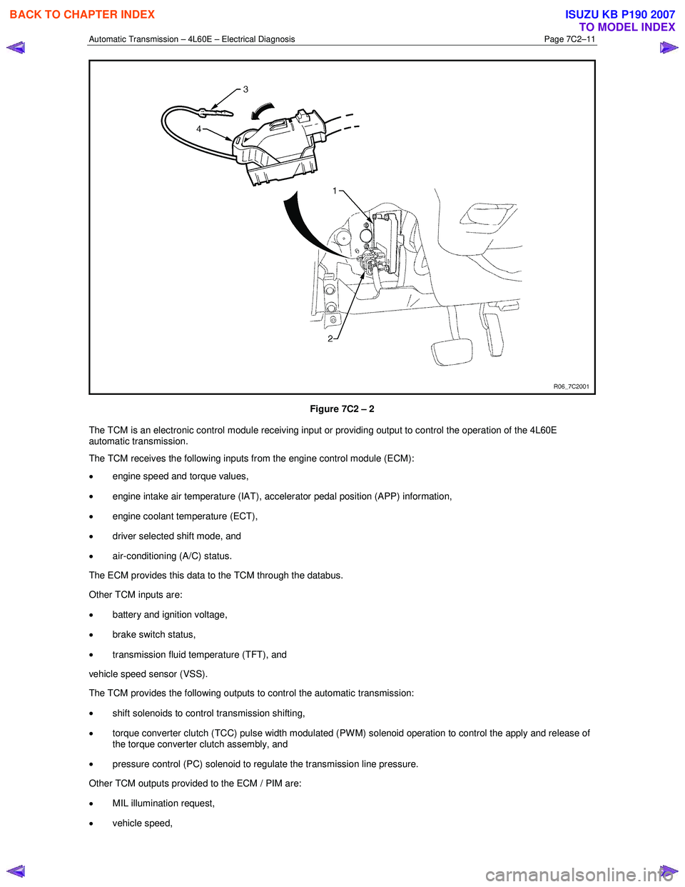
The Transmission Control Module (TCM) is located under the instrument panel, next to the brake pedal assembly and
connects directly to the transmission wiring harness. A single 49-way connector is used to make the connection between
the vehicle wiring harness and the TCM.
To access the connector for diagnosis:
1 Ensure the ignition switch is in the OFF position.
2 Disconnect the connector (1) from the transmission control module (TCM) (2) as follows, refer to Figure 7C2 – 2: a remove the securing pin (3),
b press the locking tab and swing the lever (4) to free the connector,
c remove the connector.
BACK TO CHAPTER INDEX
TO MODEL INDEX
ISUZU KB P190 2007
Page 3797 of 6020
Automatic Transmission – 4L60E – Electrical Diagnosis Page 7C2–11
Figure 7C2 – 2
The TCM is an electronic control module receiving input or providing output to control the operation of the 4L60E
automatic transmission.
The TCM receives the following inputs from the engine control module (ECM):
• engine speed and torque values,
• engine intake air temperature (IAT), accelerator pedal position (APP) information,
• engine coolant temperature (ECT),
• driver selected shift mode, and
• air-conditioning (A/C) status.
The ECM provides this data to the TCM through the databus.
Other TCM inputs are:
• battery and ignition voltage,
• brake switch status,
• transmission fluid temperature (TFT), and
vehicle speed sensor (VSS).
The TCM provides the following outputs to control the automatic transmission:
• shift solenoids to control transmission shifting,
• torque converter clutch (TCC) pulse width modulated (PW M) solenoid operation to control the apply and release of
the torque converter clutch assembly, and
• pressure control (PC) solenoid to regulate the transmission line pressure.
Other TCM outputs provided to the ECM / PIM are:
• MIL illumination request,
• vehicle speed,
BACK TO CHAPTER INDEX
TO MODEL INDEX
ISUZU KB P190 2007