2007 ISUZU KB P190 belt
[x] Cancel search: beltPage 2482 of 6020
Engine Mechanical – V6 Page 6A1–3
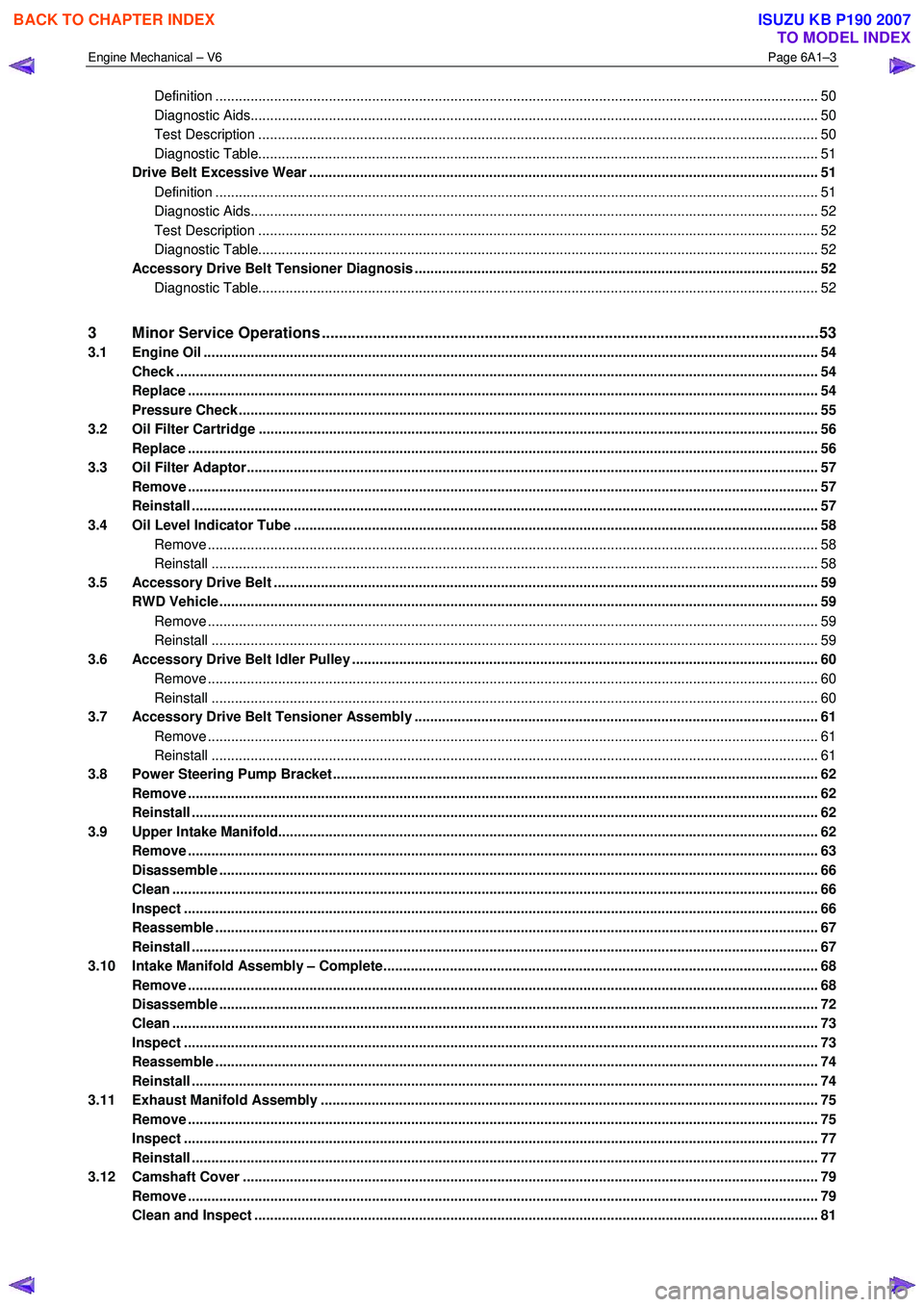
Definition .......................................................................................................................................................... 50
Diagnostic Aids................................................................................................................................................. 50
Test Description ............................................................................................................... ................................ 50
Diagnostic Table............................................................................................................................................... 51
Drive Belt Excessive Wear ...................................................................................................... ............................ 51
Definition .......................................................................................................................................................... 51
Diagnostic Aids................................................................................................................................................. 52
Test Description ............................................................................................................... ................................ 52
Diagnostic Table............................................................................................................................................... 52
Accessory Drive Belt Tensioner Diagnosis ....................................................................................... ................ 52
Diagnostic Table............................................................................................................................................... 52
3 Minor Service Operations ....................................................................................................... .............53
3.1 Engine Oil ............................................................................................................................................................. 54
Check .................................................................................................................................................................... 54
Replace ........................................................................................................................ ......................................... 54
Pressure Check ................................................................................................................. ................................... 55
3.2 Oil Filter Cartridge ............................................................................................................................................... 56
Replace ................................................................................................................................................................. 56
3.3 Oil Filter Adaptor............................................................................................................. ..................................... 57
Remove ................................................................................................................................................................. 57
Reinstall ................................................................................................................................................................ 57
3.4 Oil Level Indicator Tube ....................................................................................................... ............................... 58
Remove ............................................................................................................................................................ 58
Reinstall ........................................................................................................................................................... 58
3.5 Accessory Drive Belt ........................................................................................................... ................................ 59
RWD Vehicle ......................................................................................................................................................... 59
Remove ............................................................................................................................................................ 59
Reinstall ........................................................................................................................................................... 59
3.6 Accessory Drive Belt Idler Pulley .............................................................................................. ......................... 60
Remove ............................................................................................................................................................ 60
Reinstall ........................................................................................................................................................... 60
3.7 Accessory Drive Belt Tensioner Assembly ........................................................................................ ............... 61
Remove ............................................................................................................................................................ 61
Reinstall ........................................................................................................................................................... 61
3.8 Power Steering Pump Bracket .................................................................................................... ........................ 62
Remove ................................................................................................................................................................. 62
Reinstall ................................................................................................................................................................ 62
3.9 Upper Intake Manifold.......................................................................................................... ................................ 62
Remove ................................................................................................................................................................. 63
Disassemble ......................................................................................................................................................... 66
Clean ..................................................................................................................................................................... 66
Inspect .................................................................................................................................................................. 66
Reassemble .......................................................................................................................................................... 67
Reinstall ...................................................................................................................... .......................................... 67
3.10 Intake Manifold Assembly – Complete............................................................................................ ................... 68
Remove ................................................................................................................................................................. 68
Disassemble ......................................................................................................................................................... 72
Clean ..................................................................................................................................................................... 73
Inspect .................................................................................................................................................................. 73
Reassemble .......................................................................................................................................................... 74
Reinstall ...................................................................................................................... .......................................... 74
3.11 Exhaust Manifold Assembly ...................................................................................................... ......................... 75
Remove ................................................................................................................................................................. 75
Inspect .................................................................................................................................................................. 77
Reinstall ................................................................................................................................................................ 77
3.12 Camshaft Cover ................................................................................................................. .................................. 79
Remove ................................................................................................................................................................. 79
Clean and Inspect .............................................................................................................. .................................. 81
BACK TO CHAPTER INDEX
TO MODEL INDEX
ISUZU KB P190 2007
Page 2508 of 6020
Engine Mechanical – V6 Page 6A1–29
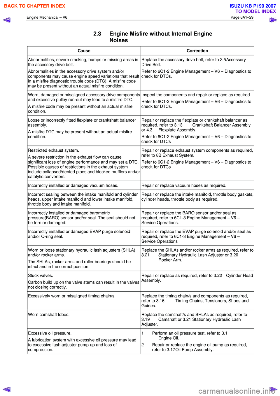
2.3 Engine Misfire without Internal Engine
Noises
Cause Correction
Abnormalities, severe cracking, bumps or missing areas in
the accessory drive belt.
Abnormalities in the accessory drive system and/or
components may cause engine speed variations that result
in a misfire diagnostic trouble code (DTC). A misfire code
may be present without an actual misfire condition. Replace the accessory drive belt, refer to 3.5
Accessory
Drive Belt.
Refer to 6C1-2 Engine Management – V6 – Diagnostics to
check for DTCs.
W orn, damaged or misaligned accessory drive components
and excessive pulley run-out may lead to a misfire DTC.
A misfire code may be present without an actual misfire
condition. Inspect the components and repair or replace as required.
Refer to 6C1-2 Engine Management – V6 – Diagnostics to
check for DTCs.
Loose or incorrectly fitted flexplate or crankshaft balancer
assembly.
A misfire DTC may be present without an actual misfire
condition. Repair or replace the flexplate or crankshaft balancer as
required, refer to 3.13 Crankshaft Balancer Assembly
or 4.3 Flexplate Assembly.
Refer to 6C1-2 Engine Management – V6 – Diagnostics to
check for DTCs
Restricted exhaust system.
A severe restriction in the exhaust flow can cause
significant loss of engine performance and may set a DTC.
Possible causes of restrictions in the exhaust system
include collapsed/dented pipes and blocked mufflers and/or
catalytic converters. Repair or replace exhaust system components as required,
refer to 8B Exhaust System.
Refer to 6C1-2 Engine Management – V6 – Diagnostics to
check for DTCs
Incorrectly installed or damaged vacuum hoses. Repair or replace vacuum hoses as required.
Incorrect sealing between the intake manifold and cylinder
heads, upper intake manifold and lower intake manifold,
throttle body and intake manifold. Repair or replace the intake manifold, throttle body gaskets,
cylinder heads, throttle body as required.
Incorrectly installed or damaged barometric
pressure(BARO) sensor and/or seal. The seal should not
be torn or damaged. Repair or replace the BARO sensor and/or seal as
required, refer to 6C1-3 Engine Management – V6 –
Service Operations.
Incorrectly installed or damaged EVAP purge solenoid
and/or O-ring seal. Repair or replace the EVAP purge solenoid and/or seal as
required, refer to 6C1-3 Engine Management – V6 –
Service Operations
W orn or loose stationary hydraulic lash adjusters (SHLA)
and/or rocker arms.
The SHLAs, rocker arms and roller bearings should be
intact and in the correct position. Replace the SHLAs and/or rocker arms as required, refer to
3.21 Stationary Hydraulic Lash Adjuster or 3.20
Rocker Arm.
Stuck valves.
Carbon build up on the valve stems can result in the valves
not closing correctly. Repair or replace as required, refer to 3.22 Cylinder Head
Assembly.
Excessively worn or misaligned timing chain/s. Replace the timing chain/s and components as required,
refer to 3.16 Timing Chains, Tensioners, Shoes and
Guides.
W orn camshaft lobes. Replace the camshaft/s and SHLAs as required, refer to
3.19 Camshaft or 3.21 Stationary Hydraulic Lash
Adjuster.
Excessive oil pressure.
A lubrication system with excessive oil pressure may lead
to excessive lash adjuster pump-up and loss of
compression. 1 Perform an oil pressure test, refer to 3.1
Engine Oil.
2 Repair or replace the engine oil pump as required, refer to 3.17 Oil Pump Assembly.
BACK TO CHAPTER INDEX
TO MODEL INDEX
ISUZU KB P190 2007
Page 2509 of 6020
Engine Mechanical – V6 Page 6A1–30
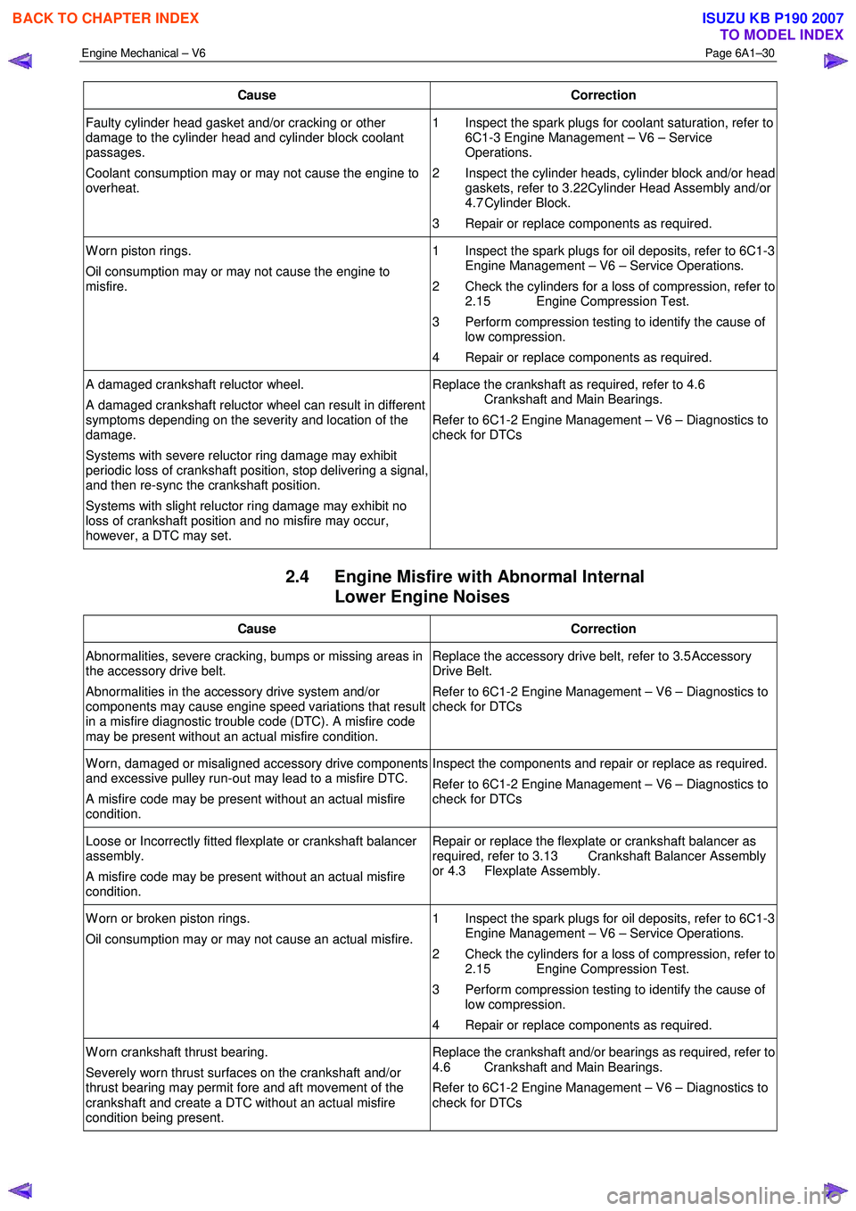
Cause Correction
Faulty cylinder head gasket and/or cracking or other
damage to the cylinder head and cylinder block coolant
passages.
Coolant consumption may or may not cause the engine to
overheat. 1 Inspect the spark plugs for coolant saturation, refer to
6C1-3 Engine Management – V6 – Service
Operations.
2 Inspect the cylinder heads, cylinder block and/or head gaskets, refer to 3.22 Cylinder Head Assembly and/or
4.7 Cylinder Block.
3 Repair or replace components as required.
W orn piston rings.
Oil consumption may or may not cause the engine to
misfire. 1 Inspect the spark plugs for oil deposits, refer to 6C1-3
Engine Management – V6 – Service Operations.
2 Check the cylinders for a loss of compression, refer to 2.15 Engine Compression Test.
3 Perform compression testing to identify the cause of low compression.
4 Repair or replace components as required.
A damaged crankshaft reluctor wheel.
A damaged crankshaft reluctor wheel can result in different
symptoms depending on the severity and location of the
damage.
Systems with severe reluctor ring damage may exhibit
periodic loss of crankshaft position, stop delivering a signal,
and then re-sync the crankshaft position.
Systems with slight reluctor ring damage may exhibit no
loss of crankshaft position and no misfire may occur,
however, a DTC may set. Replace the crankshaft as required, refer to 4.6
Crankshaft and Main Bearings.
Refer to 6C1-2 Engine Management – V6 – Diagnostics to
check for DTCs
2.4 Engine Misfire with Abnormal Internal Lower Engine Noises
Cause Correction
Abnormalities, severe cracking, bumps or missing areas in
the accessory drive belt.
Abnormalities in the accessory drive system and/or
components may cause engine speed variations that result
in a misfire diagnostic trouble code (DTC). A misfire code
may be present without an actual misfire condition. Replace the accessory drive belt, refer to 3.5
Accessory
Drive Belt.
Refer to 6C1-2 Engine Management – V6 – Diagnostics to
check for DTCs
W orn, damaged or misaligned accessory drive components
and excessive pulley run-out may lead to a misfire DTC.
A misfire code may be present without an actual misfire
condition. Inspect the components and repair or replace as required.
Refer to 6C1-2 Engine Management – V6 – Diagnostics to
check for DTCs
Loose or Incorrectly fitted flexplate or crankshaft balancer
assembly.
A misfire code may be present without an actual misfire
condition. Repair or replace the flexplate or crankshaft balancer as
required, refer to 3.13 Crankshaft Balancer Assembly
or 4.3 Flexplate Assembly.
W orn or broken piston rings.
Oil consumption may or may not cause an actual misfire. 1 Inspect the spark plugs for oil deposits, refer to 6C1-3
Engine Management – V6 – Service Operations.
2 Check the cylinders for a loss of compression, refer to 2.15 Engine Compression Test.
3 Perform compression testing to identify the cause of low compression.
4 Repair or replace components as required.
W orn crankshaft thrust bearing.
Severely worn thrust surfaces on the crankshaft and/or
thrust bearing may permit fore and aft movement of the
crankshaft and create a DTC without an actual misfire
condition being present. Replace the crankshaft and/or bearings as required, refer to
4.6 Crankshaft and Main Bearings.
Refer to 6C1-2 Engine Management – V6 – Diagnostics to
check for DTCs
BACK TO CHAPTER INDEX
TO MODEL INDEX
ISUZU KB P190 2007
Page 2513 of 6020
Engine Mechanical – V6 Page 6A1–34
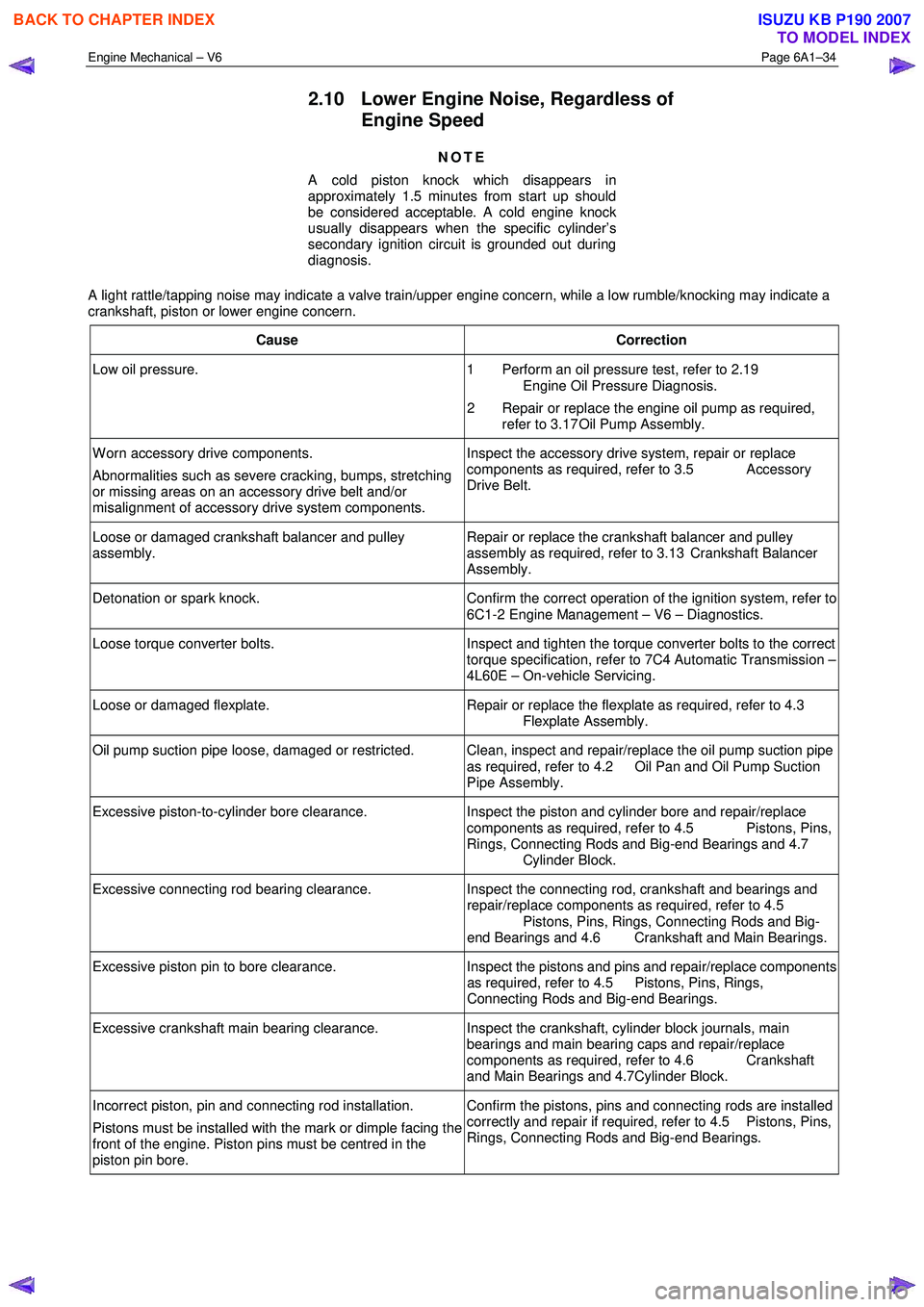
2.10 Lower Engine Noise, Regardless of
Engine Speed
NOTE
A cold piston knock which disappears in
approximately 1.5 minutes from start up should
be considered acceptable. A cold engine knock
usually disappears when the specific cylinder’s
secondary ignition circuit is grounded out during
diagnosis.
A light rattle/tapping noise may indicate a valve train/upper engine concern, while a low rumble/knocking may indicate a
crankshaft, piston or lower engine concern.
Cause Correction
Low oil pressure. 1 Perform an oil pressure test, refer to 2.19
Engine Oil Pressure Diagnosis.
2 Repair or replace the engine oil pump as required, refer to 3.17 Oil Pump Assembly.
W orn accessory drive components.
Abnormalities such as severe cracking, bumps, stretching
or missing areas on an accessory drive belt and/or
misalignment of accessory drive system components. Inspect the accessory drive system, repair or replace
components as required, refer to 3.5 Accessory
Drive Belt.
Loose or damaged crankshaft balancer and pulley
assembly. Repair or replace the crankshaft balancer and pulley
assembly as required, refer to 3.13 Crankshaft Balancer
Assembly.
Detonation or spark knock. Confirm the correct operation of the ignition system, refer to
6C1-2 Engine Management – V6 – Diagnostics.
Loose torque converter bolts. Inspect and tighten the torque converter bolts to the correct
torque specification, refer to 7C4 Automatic Transmission –
4L60E – On-vehicle Servicing.
Loose or damaged flexplate. Repair or replace the flexplate as required, refer to 4.3
Flexplate Assembly.
Oil pump suction pipe loose, damaged or restricted. Clean, inspect and repair/replace the oil pump suction pipe as required, refer to 4.2 Oil Pan and Oil Pump Suction
Pipe Assembly.
Excessive piston-to-cylinder bore clearance. Inspect the piston and cylinder bore and repair/replace
components as required, refer to 4.5 Pistons, Pins,
Rings, Connecting Rods and Big-end Bearings and 4.7
Cylinder Block.
Excessive connecting rod bearing clearance. Inspect the connecting rod, crankshaft and bearings and
repair/replace components as required, refer to 4.5
Pistons, Pins, Rings, Connecting Rods and Big-
end Bearings and 4.6 Crankshaft and Main Bearings.
Excessive piston pin to bore clearance. Inspect the pistons and pins and repair/replace components
as required, refer to 4.5 Pistons, Pins, Rings,
Connecting Rods and Big-end Bearings.
Excessive crankshaft main bearing clearance. Inspect the crankshaft, cylinder block journals, main
bearings and main bearing caps and repair/replace
components as required, refer to 4.6 Crankshaft
and Main Bearings and 4.7Cylinder Block.
Incorrect piston, pin and connecting rod installation.
Pistons must be installed with the mark or dimple facing the
front of the engine. Piston pins must be centred in the
piston pin bore. Confirm the pistons, pins and connecting rods are installed
correctly and repair if required, refer to 4.5 Pistons, Pins,
Rings, Connecting Rods and Big-end Bearings.
BACK TO CHAPTER INDEX
TO MODEL INDEX
ISUZU KB P190 2007
Page 2514 of 6020
Engine Mechanical – V6 Page 6A1–35
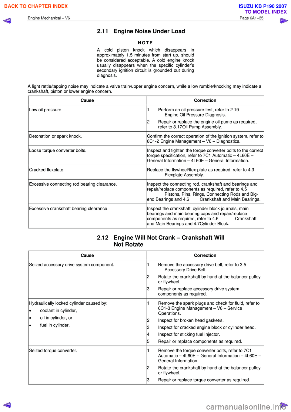
2.11 Engine Noise Under Load
NOTE
A cold piston knock which disappears in
approximately 1.5 minutes from start up, should
be considered acceptable. A cold engine knock
usually disappears when the specific cylinder’s
secondary ignition circuit is grounded out during
diagnosis.
A light rattle/tapping noise may indicate a valve train/upper engine concern, while a low rumble/knocking may indicate a
crankshaft, piston or lower engine concern.
Cause Correction
Low oil pressure. 1 Perform an oil pressure test, refer to 2.19
Engine Oil Pressure Diagnosis.
2 Repair or replace the engine oil pump as required, refer to 3.17 Oil Pump Assembly.
Detonation or spark knock. Confirm the correct operation of the ignition system, refer to
6C1-2 Engine Management – V6 – Diagnostics.
Loose torque converter bolts. Inspect and tighten the torque converter bolts to the correct
torque specification, refer to 7C1 Automatic – 4L60E –
General Information – 4L60E – General Information.
Cracked flexplate. Replace the flywheel/flex-plate as required, refer to 4.3
Flexplate Assembly.
Excessive connecting rod bearing clearance. Inspect the connecting rod, crankshaft and bearings and
repair/replace components as required, refer to 4.5
Pistons, Pins, Rings, Connecting Rods and Big-
end Bearings and 4.6 Crankshaft and Main Bearings.
Excessive crankshaft bearing clearance Inspect the crankshaft, cylinder block journals, main
bearings and main bearing caps and repair/replace
components as required, refer to 4.6 Crankshaft
and Main Bearings and 4.7Cylinder Block.
2.12 Engine Will Not Crank – Crankshaft Will Not Rotate
Cause Correction
Seized accessory drive system component. 1 Remove the accessory drive belt, refer to 3.5
Accessory Drive Belt.
2 Rotate the crankshaft by hand at the balancer pulley or flywheel.
3 Repair or replace accessory drive system components as required.
Hydraulically locked cylinder caused by:
• coolant in cylinder,
• oil in cylinder, or
• fuel in cylinder. 1 Remove the spark plugs and check for fluid, refer to
6C1-3 Engine Management – V6 – Service
Operations.
2 Inspect for broken head gasket/s.
3 Inspect for cracked engine block or cylinder head.
4 Inspect for sticking fuel injector.
5 Repair or replace components as required.
Seized torque converter. 1 Remove the torque converter bolts, refer to 7C1
Automatic – 4L60E – General Information – 4L60E –
General Information.
2 Rotate the crankshaft by hand at the balancer pulley or flywheel.
3 Repair or replace torque converter as required.
BACK TO CHAPTER INDEX
TO MODEL INDEX
ISUZU KB P190 2007
Page 2521 of 6020
Engine Mechanical – V6 Page 6A1–42
2.19 Engine Oil Pressure Diagnosis
If the engine oil pressure is below the specified value, inspect the engine and components for the following:
• loose oil filter adaptor bolts,
• faulty oil filter adaptor seals,
• worn or faulty oil pump,
• loose oil pump bolts,
• loose, blocked or damaged oil pump suction pipe,
• faulty oil pump suction pipe seal,
• faulty oil pump pressure relief valve,
• faulty or incorrectly installed oil gallery plugs,
• excessive bearing clearance in one of the following:
• connecting rods big end/s,
• crankshaft main journal/s,
• camshaft/s,
• camshaft sprocket/s, and
• cracked, porous or restricted oil galleries, or broken lash adjuster/s.
2.20 Accessory Drive Belt Diagnosis
Tension Check
NOTE
An accessory drive belt that squeaks when the
engine is started or stopped is considered normal
and has no effect on drive belt durability.
1 Start the engine and switch off the air-conditioning system. Allow engine to run until normal operating temperature has been reached.
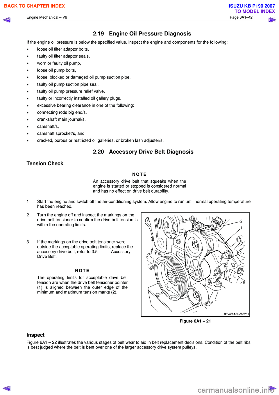
2 Turn the engine off and inspect the markings on the drive belt tensioner to confirm the drive belt tension is
within the operating limits.
3 If the markings on the drive belt tensioner were outside the acceptable operating limits, replace the
accessory drive belt, refer to 3.5 Accessory
Drive Belt.
NOTE
The operating limits for acceptable drive belt
tension are when the drive belt tensioner pointer
(1) is aligned between the outer edge of the
minimum and maximum tension marks (2).
Figure 6A1 – 21
Inspect
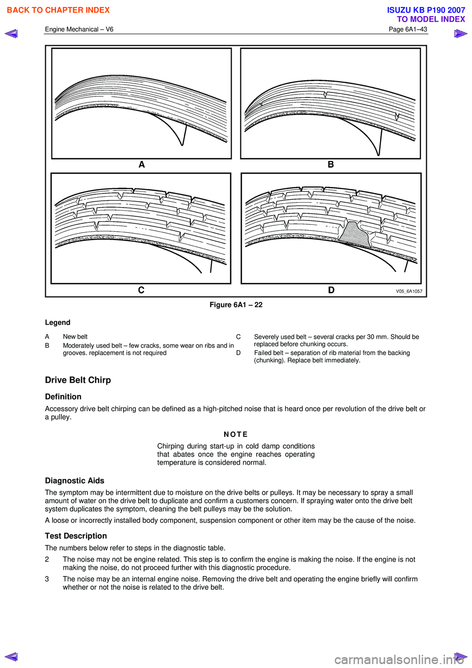
Figure 6A1 – 22 illustrates the various stages of belt wear to aid in belt replacement decisions. Condition of the belt ribs
is best judged where the belt is bent over one of the larger accessory drive system pulleys.
BACK TO CHAPTER INDEX
TO MODEL INDEX
ISUZU KB P190 2007
Page 2522 of 6020
Engine Mechanical – V6 Page 6A1–43
Figure 6A1 – 22
Legend
A New belt
B Moderately used belt – few cra cks, some wear on ribs and in
grooves. replacement is not required C Severely used belt – several cracks per 30 mm. S
hould be
replaced before chunking occurs.
D Failed belt – separation of rib material from the backing (chunking). Replace belt immediately.
Drive Belt Chirp
Definition
Accessory drive belt chirping can be defined as a high-pitched noise that is heard once per revolution of the drive belt or
a pulley.
NOTE
Chirping during start-up in cold damp conditions
that abates once the engine reaches operating
temperature is considered normal.
Diagnostic Aids
The symptom may be intermittent due to moisture on the drive belts or pulleys. It may be necessary to spray a small
amount of water on the drive belt to duplicate and confirm a customers concern. If spraying water onto the drive belt
system duplicates the symptom, cleaning the belt pulleys may be the solution.
A loose or incorrectly installed body component, suspension component or other item may be the cause of the noise.
Test Description
The numbers below refer to steps in the diagnostic table.
2 The noise may not be engine related. This step is to confirm the engine is making the noise. If the engine is not making the noise, do not proceed further with this diagnostic procedure.
3 The noise may be an internal engine noise. Removing the drive belt and operating the engine briefly will confirm whether or not the noise is related to the drive belt.
BACK TO CHAPTER INDEX
TO MODEL INDEX
ISUZU KB P190 2007
Page 2523 of 6020
Engine Mechanical – V6 Page 6A1–44
CAUTION
When running the engine with the accessory
drive belt removed, the coolant pump will not
be operating and the engine may overheat if
left unsupervised even for a short period.
NOTE
There may also be a number of DTCs set when
running the engine with the accessory drive belt
removed.
4 Inspect all drive pump pulleys for pilling. NOTE
Pilling is the small balls (pills) or strings of rubber
in the belt grooves caused by the accumulation of
rubber dust.
6 Misalignment of the accessory drive system pulleys may be caused by incorrect mounting of an accessory drive component (A/C compressor, generator etc.) or pulley. Misalignment may also be caused by incorrect installation of
a pulley during a previous repair. Test for a misaligned pulley using a straight edge in the pulley grooves across
two or three pulleys. If a misaligned pulley is found, refer to the relevant component service information for the
correct installation and removal procedures.
10 Inspecting the fasteners can eliminate the possibility that an incorrect fastener has been installed.
12 Inspecting the pulleys for being bent should include inspecting for a dent or other damage that would prevent the drive belt from not seating correctly in all of the pulley grooves or on the smooth surface when the back end of the
belt is used as the driving surface.
14 Replacing the drive belt when it is not damaged and there is no excessive pilling will only be a temporary repair.
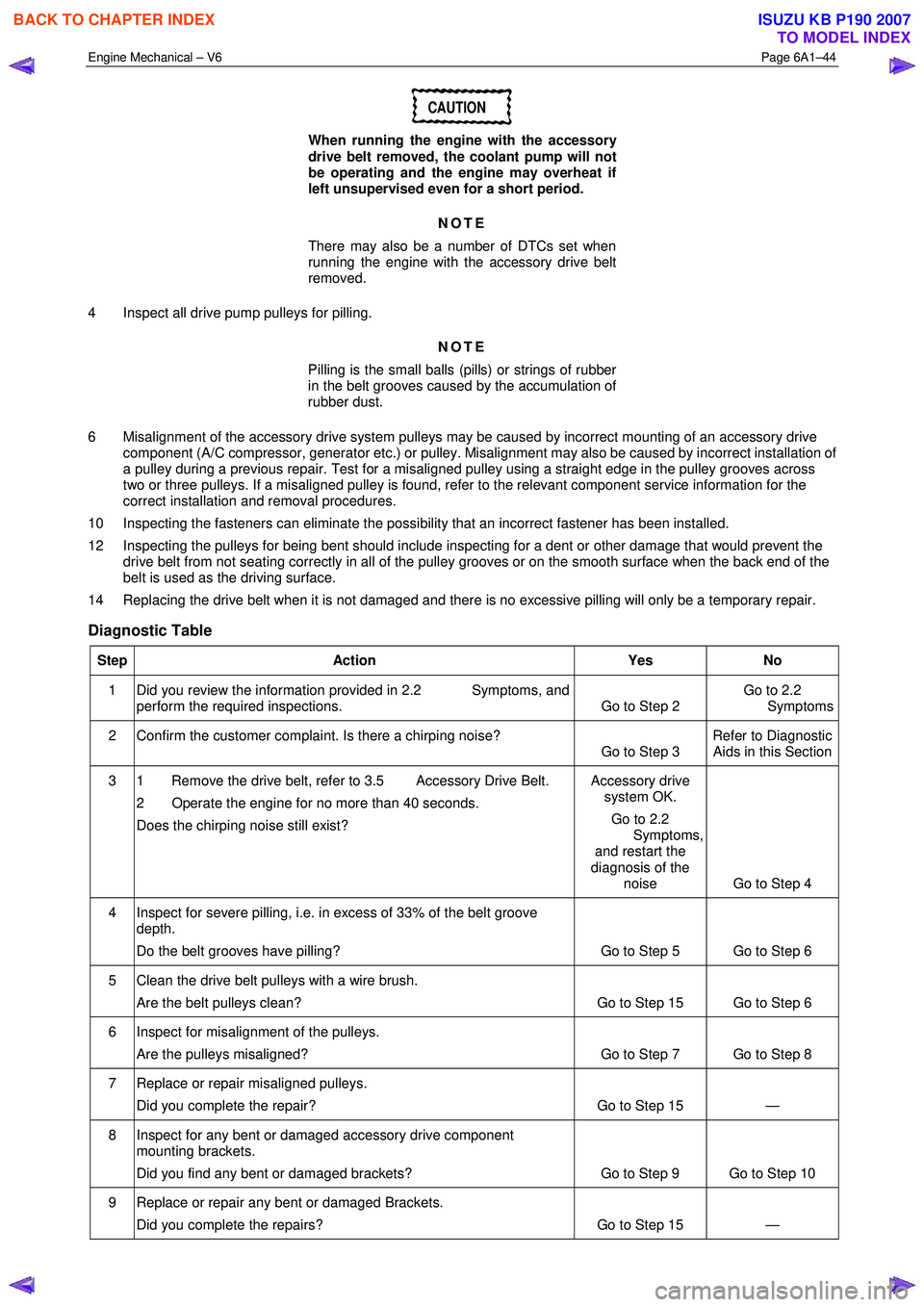
Diagnostic Table
Step Action Yes No
1 Did you review the information provided in 2.2 Symptoms, and
perform the required inspections. Go to Step 2 Go to 2.2
Symptoms
2 Confirm the customer complaint. Is there a chirping noise? Go to Step 3 Refer to Diagnostic
Aids in this Section
3 1 Remove the drive belt, refer to 3.5 Accessory Drive Belt.
2 Operate the engine for no more than 40 seconds.
Does the chirping noise still exist? Accessory drive
system OK.
Go to 2.2
Symptoms, and restart the
diagnosis of the noise Go to Step 4
4 Inspect for severe pilling, i.e. in excess of 33% of the belt groove
depth.
Do the belt grooves have pilling? Go to Step 5 Go to Step 6
5 Clean the drive belt pulleys with a wire brush. Are the belt pulleys clean? Go to Step 15 Go to Step 6
6 Inspect for misalignment of the pulleys. Are the pulleys misaligned? Go to Step 7 Go to Step 8
7 Replace or repair misaligned pulleys. Did you complete the repair? Go to Step 15 —
8 Inspect for any bent or damaged accessory drive component mounting brackets.
Did you find any bent or damaged brackets? Go to Step 9 Go to Step 10
9 Replace or repair any bent or damaged Brackets. Did you complete the repairs? Go to Step 15 —
BACK TO CHAPTER INDEX
TO MODEL INDEX
ISUZU KB P190 2007