Page 168 of 441

Features of your vehicle86 4❈
❈
2nd row outlet vents (E)
• The air flow of the 2nd row outlet vents
is controlled by the front climate control
system and delivered through the
inside air duct of the front doors. If the
door is open or not closed completely,
the air flow of the 2nd row outlet vent is
not delivered properly. Make sure the
front doors are closed completely.
The air flow of the 2nd row outlet vents
may be weaker than the instrument
panel vents for the long air duct in the
front doors.
Close the air vents in cold weather. The
air flow of the 2nd row outlet vents may
cool a little during heating operation.
(Use the 2nd row outlet vents during
cooling operation.)
D230101AEN-EUMode selectionThe mode selection knob controls the
direction of the air flow through the venti-
lation system.
Air can be directed to the floor, dash-
board outlets, or windshield. Six symbols
are used to represent MAX A/C, Face,
Bi-Level, Floor, Floor-Defrost and Defrost
air position.
The MAX A/C mode is used to cool the
inside of the vehicle faster.
MAX A/C-Level (B, D, E)
Air flow is directed toward the upper body
and face.
In this mode, the air conditioning and the
recirculated air position will be selected
automatically.
Face-Level (B, D, E)
Air flow is directed toward the upper body
and face. Additionally, each outlet can be
controlled to direct the air discharged
from the outlet.
Bi-Level (B, D, E, C, F)
Air flow is directed towards the face and
the floor.
Off-Mode
The fan is turned off.
OEN046096N
EN hma 4-84~120.qxd 11/27/2006 5:30 PM Page 86
procarmanuals.com
Page 169 of 441

487
Features of your vehicle
Floor-Level (C, F, A, D, E)
Most of the air flow is directed to the
floor, with a small amount of the air being
directed to the windshield and side win-
dow defrosters.
Floor/Defrost-Level (A, C, F, D, E)
Most of the air flow is directed to the floor
and the windshield with a small amount
directed to the side window defrosters.
Defrost-Level (A, D, E)
Most of the air flow is directed to the
windshield with a small amount of air
directed to the side window defrosters.Instrument panel vents
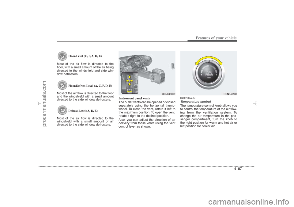
The outlet vents can be opened or closed
separately using the horizontal thumb-
wheel. To close the vent, rotate it left to
the maximum position. To open the vent,
rotate it right to the desired position.
Also, you can adjust the direction of air
delivery from these vents using the vent
control lever as shown.
D230102AUNTemperature controlThe temperature control knob allows you
to control the temperature of the air flow-
ing from the ventilation system. To
change the air temperature in the pas-
senger compartment, turn the knob to
the right position for warm and hot air or
left position for cooler air.
OEN046100
OEN046099
EN hma 4-84~120.qxd 11/27/2006 5:30 PM Page 87
procarmanuals.com
Page 179 of 441

497
Features of your vehicle
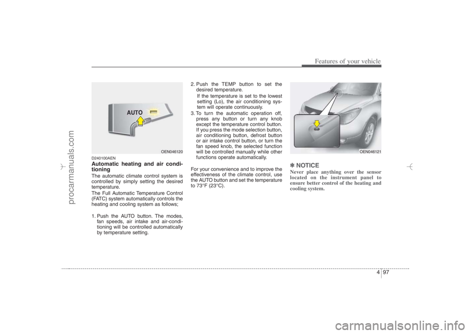
D240100AENAutomatic heating and air condi-
tioningThe automatic climate control system is
controlled by simply setting the desired
temperature.
The Full Automatic Temperature Control
(FATC) system automatically controls the
heating and cooling system as follows;
1. Push the AUTO button. The modes,
fan speeds, air intake and air-condi-
tioning will be controlled automatically
by temperature setting.2. Push the TEMP button to set the
desired temperature.
If the temperature is set to the lowest
setting (Lo), the air conditioning sys-
tem will operate continuously.
3. To turn the automatic operation off,
press any button or turn any knob
except the temperature control button.
If you press the mode selection button,
air conditioning button, defrost button
or air intake control button, or turn the
fan speed knob, the selected function
will be controlled manually while other
functions operate automatically.
For your convenience and to improve the
effectiveness of the climate control, use
the AUTO button and set the temperature
to 73°F (23°C).
✽ ✽
NOTICENever place anything over the sensor
located on the instrument panel to
ensure better control of the heating and
cooling system.
OEN046121
OEN046120
EN hma 4-84~120.qxd 11/27/2006 5:32 PM Page 97
procarmanuals.com
Page 181 of 441
499
Features of your vehicle
Defrost-Level (A, D, E)
Most of the air flow is directed to the
windshield with a small amount of air
directed to the side window defrosters.Instrument panel vents
The outlet vents can be opened or closed
separately using the horizontal thumb-
wheel. To close the vent, rotate it left to
the maximum position. To open the vent,
rotate it right to the desired position.
Also, you can adjust the direction of air
delivery from these vents using the vent
control lever as shown.
D240202AEN-EUTemperature controlThe temperature will increase to the
maximum (HI) by pushing the up ( )
button.
The temperature will decrease to the min-
imum (Lo) by pushing the down ( ) but-
ton.
When pushing the button, the tempera-
ture will increase or decrease by
1°F/0.5°C. When set to the lowest tem-
perature setting, the air conditioning will
operate continuously.
OEN046123
OEN046099
OEN046124
EN hma 4-84~120.qxd 11/27/2006 5:32 PM Page 99
procarmanuals.com
Page 278 of 441

57
Driving your vehicle
WARNING
The ignition switch will turn, and
the engine will start, only when the
smart key is in the vehicle and the
brake has been depressed.
Never allow children or any person
who is unfamiliar with the vehicle
to touch the ignition switch or relat-
ed parts.
3. Leave the smart key inside the vehicle.
4. Depress the brake pedal.
5. Depress and hold the ignition switch.
The immobilizer indicator ( ) illu-
minates on the instrument panel for
approximately 10 seconds.
6. With the ignition switch depressed and
held, start the engine by turning the
ignition switch on.
If the ignition switch is released, the
ignition switch will be locked. If this
occurs, repeat the above steps.
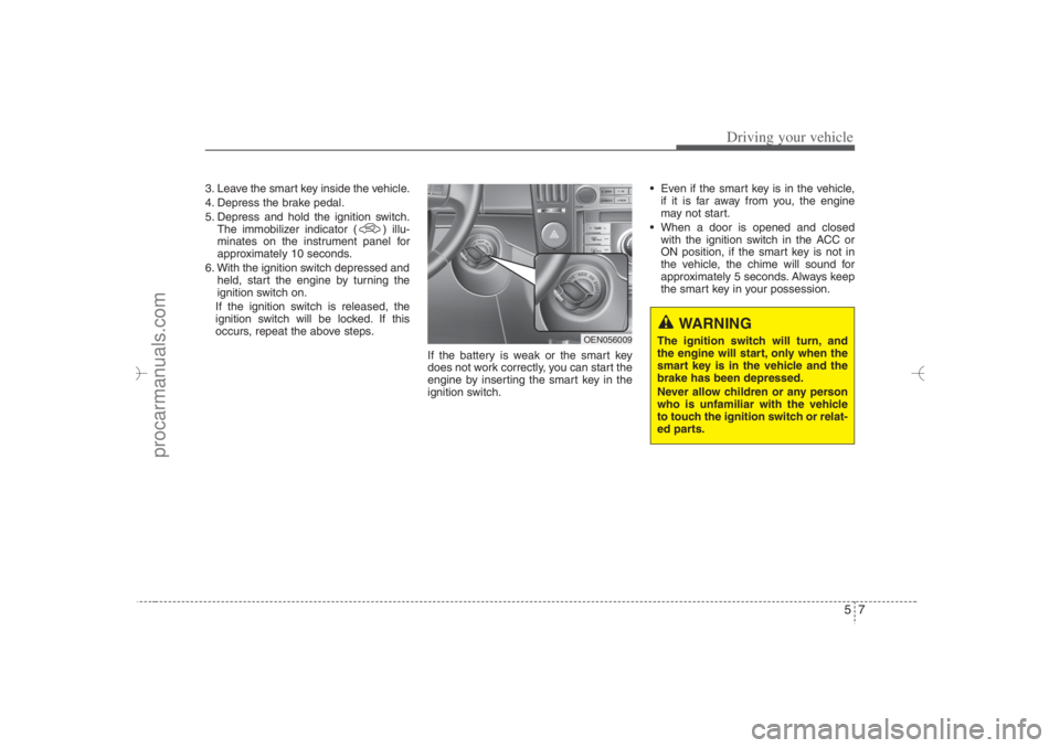
If the battery is weak or the smart key
does not work correctly, you can start the
engine by inserting the smart key in the
ignition switch. Even if the smart key is in the vehicle,
if it is far away from you, the engine
may not start.
When a door is opened and closed
with the ignition switch in the ACC or
ON position, if the smart key is not in
the vehicle, the chime will sound for
approximately 5 seconds. Always keep
the smart key in your possession.
OEN056009
EN hma 5.qxd 11/28/2006 2:58 PM Page 7
procarmanuals.com
Page 319 of 441

Driving your vehicle48 5E140400AUNDriving with a trailer Towing a trailer requires a certain
amount of experience. Before setting out
for the open road, you must get to know
your trailer. Acquaint yourself with the
feel of handling and braking with the
added weight of the trailer. And always
keep in mind that the vehicle you are
driving is now a good deal longer and not
nearly so responsive as your vehicle is
by itself.
Before you start, check the trailer hitch
and platform, safety chains, electrical
connector(s), lights, tires and mirror
adjustment. If the trailer has electric
brakes, start your vehicle and trailer mov-
ing and then apply the trailer brake con-
troller by hand to be sure the brakes are
working. This lets you check your electri-
cal connection at the same time.
During your trip, check occasionally to be
sure that the load is secure, and that the
lights and any trailer brakes are still work-
ing.
E140401AUNFollowing distance Stay at least twice as far behind the vehi-
cle ahead as you would when driving
your vehicle without a trailer. This can
help you avoid situations that require
heavy braking and sudden turns.E140402AUNPassing You’ll need more passing distance up
ahead when you’re towing a trailer. And,
because of the increased vehicle length,
you’ll need to go much farther beyond the
passed vehicle before you can return to
your lane.E140403AUNBacking up Hold the bottom of the steering wheel
with one hand. Then, to move the trailer
to the left, just move your hand to the left.
To move the trailer to the right, move your
hand to the right. Always back up slowly
and, if possible, have someone guide
you.
E140404AUNMaking turns When you’re turning with a trailer, make
wider turns than normal. Do this so your
trailer won’t strike soft shoulders, curbs,
road signs, trees, or other objects. Avoid
jerky or sudden maneuvers. Signal well
in advance.E140405AENTurn signals when towing a trailer When you tow a trailer, your vehicle has
to have a different turn signal flasher and
extra wiring. The green arrows on your
instrument panel will flash whenever you
signal a turn or lane change. Properly
connected, the trailer lights will also flash
to alert other drivers you’re about to turn,
change lanes, or stop.
When towing a trailer, the green arrows
on your instrument panel will flash for
turns even if the bulbs on the trailer are
burned out. Thus, you may think drivers
behind you are seeing your signals
when, in fact, they are not. It’s important
to check occasionally to be sure the trail-
er bulbs are still working. You must also
check the lights every time you discon-
nect and then reconnect the wires.
Do not connect a trailer lighting system
directly to your vehicle’s lighting system.
Use only an approved trailer wiring har-
ness.
EN hma 5.qxd 11/28/2006 3:01 PM Page 48
procarmanuals.com
Page 398 of 441
Maintenance44 7G210100AENInstrument panel fuse replace-
ment1. Turn the ignition switch and all other
switches off.
2. Open the fuse panel cover.3. Pull the suspected fuse straight out.
Use the removal tool provided in the
fuse panel cover.
4. Check the removed fuse; replace it if it
is blown.
Spare fuses are provided in the inner
fuse panel (or in the engine compart-
ment fuse panel).5. Push in a new fuse of the same rating,
and make sure it fits tightly in the clips.
If it fits loosely, consult an authorized
HYUNDAI dealer.If you do not have a spare, use a fuse of
the same rating from a circuit you may
not need for operating the vehicle, such
as the cigarette lighter fuse.
If the headlights or other electrical com-
ponents do not work and the fuses are
OK, check the fuse panel in the engine
compartment. If a fuse is blown, it must
be replaced.
OEN076022
OEN076021
EN hma 7.qxd 11/28/2006 3:45 PM Page 44
procarmanuals.com
Page 401 of 441
747
Maintenance
✽ ✽
NOTICENot all fuse panel descriptions in this
manual may be applicable to your vehi-
cle. It is accurate at the time of printing.
When you inspect the fuse panel in your
vehicle, refer to the fuse panel label.
Instrument panel fuse panel
Engine compartment fuse panel
OEN076027/OEN076028/OEN076029N G210300AEN-EU
Fuse/relay panel descriptionInside the fuse/relay panel covers, you can find the fuse/relay label describing fuse/relay name and capacity.
EN hma 7.qxd 11/28/2006 3:46 PM Page 47
procarmanuals.com