2007 HYUNDAI TUCSON maintenance schedule
[x] Cancel search: maintenance schedulePage 241 of 306
6
DO-IT-YOURSELF MAINTENANCE
6
WARNING:
Be very careful not to touch the radiator
hose when adding the engine oil as it may
be hot enough to burn you.
!
CHANGING THE OIL AND FILTER
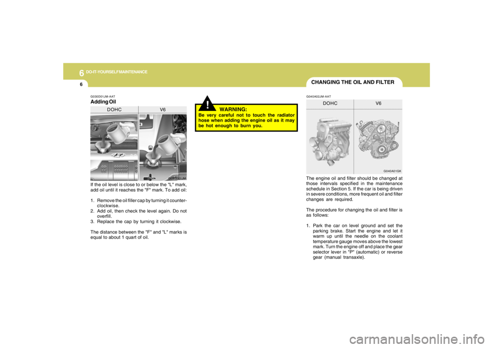
If the oil level is close to or below the "L" mark,
add oil until it reaches the "F" mark. To add oil:
1. Remove the oil filler cap by turning it counter-
clockwise.
2. Add oil, then check the level again. Do not
overfill.
3. Replace the cap by turning it clockwise.
The distance between the "F" and "L" marks is
equal to about 1 quart of oil.The engine oil and filter should be changed at
those intervals specified in the maintenance
schedule in Section 5. If the car is being driven
in severe conditions, more frequent oil and filter
changes are required.
The procedure for changing the oil and filter is
as follows:
1. Park the car on level ground and set the
parking brake. Start the engine and let it
warm up until the needle on the coolant
temperature gauge moves above the lowest
mark. Turn the engine off and place the gear
selector lever in "P" (automatic) or reverse
gear (manual transaxle).G030D01JM-AATAdding Oil
G030D01JM
DOHC V6
G040A01GK
DOHC V6
G040A02JM-AAT
Page 244 of 306
6
DO-IT-YOURSELF MAINTENANCE
9
!
!
WARNING:
The cooling fan is controlled by engine
coolant temperature and may sometimes
operate even when the engine is not run-
ning. Use extreme caution when working
near the blades of the coolant fan so that
you are not injured by a rotating fan blade.
As the engine coolant temperature de-
creases, the fan will automatically shut off.
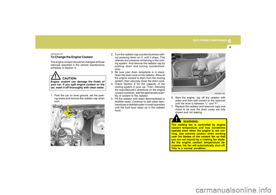
This is a normal condition. 2. Turn the radiator cap counterclockwise with-
out pressing down on it, until it stops. This
relieves any pressure remaining in the cool-
ing system. And remove the radiator cap by
pushing down and turning counterclock-
wise.
3. Be sure your drain receptacle is in place.
Open the drain cock on the radiator. Allow all
the engine coolant to drain from the cooling
system, then securely close the drain cock.
4. Check Section 9 for the capacity of the
cooling system in your car. Then, following
the manufacturer's directions on the engine
coolant container, add the appropriate quan-
tity of coolant to the radiator.
5. Fill the radiator with clean demineralized or
distilled water. Continue to add clean dem-
ineralized or distilled water in small quantities
until the fluid level stays up in the radiator
neck.6. Start the engine, top off the radiator with
water and then add coolant to the reservoir
until the level is between "L" and "F".
7. Replace the radiator and reservoir caps and
check to be sure the drain cocks are fully
closed and not leaking.
G050D02A-AATTo Change the Engine CoolantThe engine coolant should be changed at those
intervals specified in the vehicle maintenance
schedule in Section 5.
HJM5034G050D01JM
CAUTION:
Engine coolant can damage the finish of
your car. If you spill engine coolant on the
car, wash it off thoroughly with clean water.
1. Park the car on level ground, set the park-
ing brake and remove the radiator cap when
cool.
Page 246 of 306
6
DO-IT-YOURSELF MAINTENANCE
11
G090A01JM
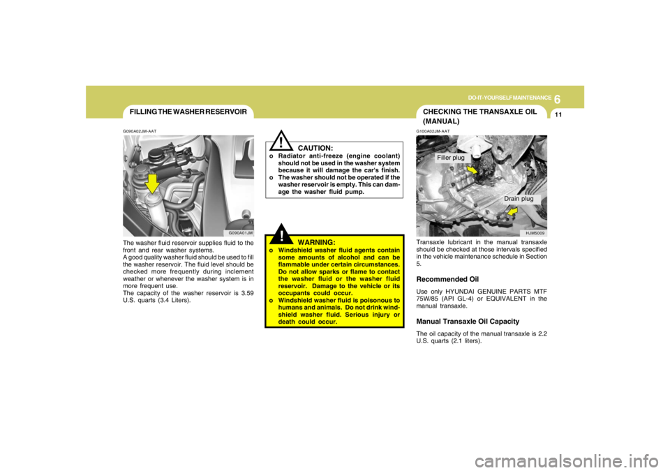
FILLING THE WASHER RESERVOIRG090A02JM-AATThe washer fluid reservoir supplies fluid to the
front and rear washer systems.
A good quality washer fluid should be used to fill
the washer reservoir. The fluid level should be
checked more frequently during inclement
weather or whenever the washer system is in
more frequent use.
The capacity of the washer reservoir is 3.59
U.S. quarts (3.4 Liters).
CAUTION:
o Radiator anti-freeze (engine coolant)
should not be used in the washer system
because it will damage the car's finish.
o The washer should not be operated if the
washer reservoir is empty. This can dam-
age the washer fluid pump.
!!
WARNING:
o Windshield washer fluid agents contain
some amounts of alcohol and can be
flammable under certain circumstances.
Do not allow sparks or flame to contact
the washer fluid or the washer fluid
reservoir. Damage to the vehicle or its
occupants could occur.
o Windshield washer fluid is poisonous to
humans and animals. Do not drink wind-
shield washer fluid. Serious injury or
death could occur.
CHECKING THE TRANSAXLE OIL
(MANUAL)G100A02JM-AATTransaxle lubricant in the manual transaxle
should be checked at those intervals specified
in the vehicle maintenance schedule in Section
5.Recommended OilUse only HYUNDAI GENUINE PARTS MTF
75W/85 (API GL-4) or EQUIVALENT in the
manual transaxle.Manual Transaxle Oil CapacityThe oil capacity of the manual transaxle is 2.2
U.S. quarts (2.1 liters).
HJM5009
Filler plug
Drain plug
Page 247 of 306
6
DO-IT-YOURSELF MAINTENANCE
12
CHECKING THE TRANSAXLE
FLUID (AUTOMATIC)G110A01E-AATTransaxle fluid in the automatic transaxle should
be checked at those intervals specified in the
vehicle maintenance schedule in Section 5.NOTE:Automatic transaxle fluid is basically red
color. As driving distance increases, the
fluid color turns darkish red gradually. It is
a normal condition and you should not
judge the need to replace based upon the
changing color.
You must replace the automatic transaxle
fluid in accordance with intervals specified
in the vehicle maintenance schedule in
section 5.
G100B01L
!
G100B02A-AATTo Check the Manual Transaxle Fluid
Level
WARNING:
It is always better to check the transaxle oil
level when the engine is cool or cold. If the
engine is hot, you should exercise great
caution to avoid burning yourself on hot
engine or exhaust parts.
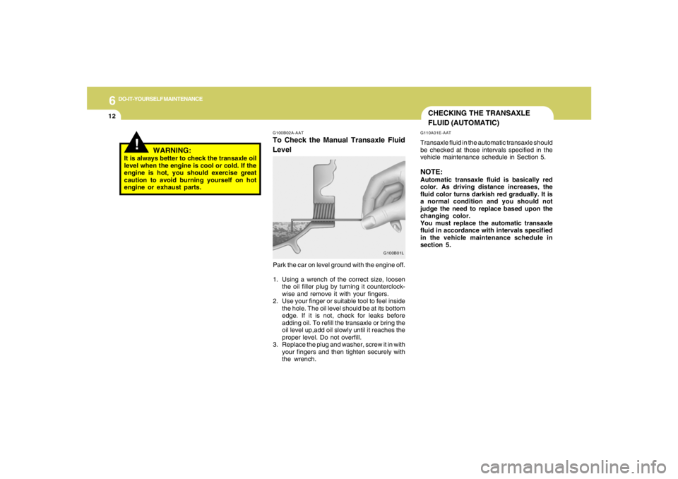
Park the car on level ground with the engine off.
1. Using a wrench of the correct size, loosen
the oil filler plug by turning it counterclock-
wise and remove it with your fingers.
2. Use your finger or suitable tool to feel inside
the hole. The oil level should be at its bottom
edge. If it is not, check for leaks before
adding oil. To refill the transaxle or bring the
oil level up,add oil slowly until it reaches the
proper level. Do not overfill.
3. Replace the plug and washer, screw it in with
your fingers and then tighten securely with
the wrench.
Page 249 of 306
6
DO-IT-YOURSELF MAINTENANCE
14
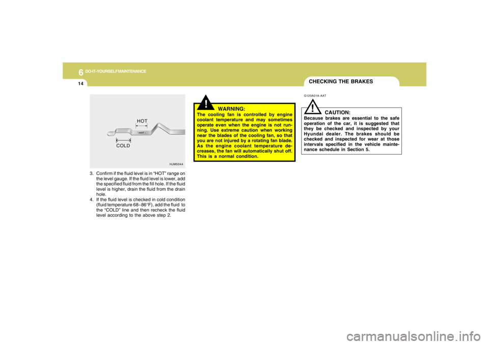
3. Confirm if the fluid level is in “HOT” range on
the level gauge. If the fluid level is lower, add
the specified fluid from the fill hole. If the fluid
level is higher, drain the fluid from the drain
hole.
4. If the fluid level is checked in cold condition
(fluid temperature 68~86°F), add the fluid to
the “COLD” line and then recheck the fluid
level according to the above step 2.
HJM5044
CHECKING THE BRAKES
!
WARNING:
The cooling fan is controlled by engine
coolant temperature and may sometimes
operate even when the engine is not run-
ning. Use extreme caution when working
near the blades of the cooling fan, so that
you are not injured by a rotating fan blade.
As the engine coolant temperature de-
creases, the fan will automatically shut off.
This is a normal condition. HOT
G120A01A-AAT
CAUTION:
Because brakes are essential to the safe
operation of the car, it is suggested that
they be checked and inspected by your
Hyundai dealer. The brakes should be
checked and inspected for wear at those
intervals specified in the vehicle mainte-
nance schedule in Section 5.
!
COLD
Page 260 of 306
6
DO-IT-YOURSELF MAINTENANCE
25
HEADLIGHT AIMING ADJUSTMENT
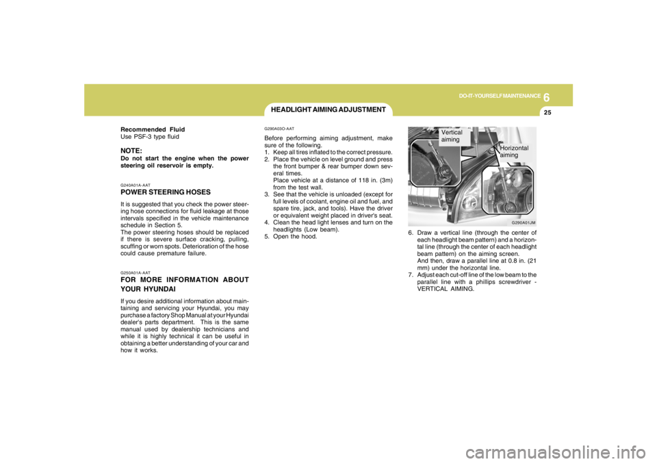
6. Draw a vertical line (through the center of
each headlight beam pattern) and a horizon-
tal line (through the center of each headlight
beam pattern) on the aiming screen.
And then, draw a parallel line at 0.8 in. (21
mm) under the horizontal line.
7. Adjust each cut-off line of the low beam to the
parallel line with a phillips screwdriver -
VERTICAL AIMING.
G290A03O-AATBefore performing aiming adjustment, make
sure of the following.
1. Keep all tires inflated to the correct pressure.
2. Place the vehicle on level ground and press
the front bumper & rear bumper down sev-
eral times.
Place vehicle at a distance of 118 in. (3m)
from the test wall.
3. See that the vehicle is unloaded (except for
full levels of coolant, engine oil and fuel, and
spare tire, jack, and tools). Have the driver
or equivalent weight placed in driver's seat.
4. Clean the head light lenses and turn on the
headlights (Low beam).
5. Open the hood.
G250A01A-AATFOR MORE INFORMATION ABOUT
YOUR HYUNDAIIf you desire additional information about main-
taining and servicing your Hyundai, you may
purchase a factory Shop Manual at your Hyundai
dealer's parts department. This is the same
manual used by dealership technicians and
while it is highly technical it can be useful in
obtaining a better understanding of your car and
how it works.G240A01A-AATPOWER STEERING HOSESIt is suggested that you check the power steer-
ing hose connections for fluid leakage at those
intervals specified in the vehicle maintenance
schedule in Section 5.
The power steering hoses should be replaced
if there is severe surface cracking, pulling,
scuffing or worn spots. Deterioration of the hose
could cause premature failure. Recommended Fluid
Use PSF-3 type fluidNOTE:Do not start the engine when the power
steering oil reservoir is empty.
G290A01JM
Vertical
aiming
Horizontal
aiming
Page 275 of 306
7
EMISSION CONTROL SYSTEMS2
EMISSION CONTROL SYSTEM
H010D01A-AAT3. Exhaust Emission Control SystemThe Exhaust Emission Control System is a
highly effective system which controls exhaust
emissions while maintaining good vehicle
performace.
H010B01A-AAT1. Crankcase Emission Control
SystemThe positive crankcase ventilation system is
employed to prevent air pollution caused by
blow-by gases being emitted from the crank-
case. This system supplies filtered air to the
crankcase through the air intake hose. Inside
the crankcase, the fresh air mixes with blow-by
gases, which then pass through the PCV valve
and into the induction system.
H010A02O-AATYour Hyundai is equipped with an emission
control system to meet all requirements of the
U.S. Environmental Protection Agency or Cali-
fornia Air Resources Board.
There are three emission control systems which
are as follows.
(1) Crankcase emission control system
(2) Evaporative emission control system
(3) Exhaust emission control system
In order to assure the proper function of the
emission control systems, it is recommended
that you have your car inspected and main-
tained by an authorized Hyundai dealer in ac-
cordance with the maintenance schedule in this
manual.
Caution for the Inspection and Maintenance
Test (V6 Vehicle with Traction Control Sys-
tem)
o To prevent the vehicle from misfiring
during dynamometer testing, discon-
nect the ABS connector in the engine
compartment. (2.7 V6 only)
o For more information, see shop manual
(Wheel Speed Sensor).
o After dynamometer testing is completed,
erase the ABS/TCS DTC (Diagnotic
Trouble Code) with a GST (Generic Scan
Tool) or Hi-Scan Pro.
CanisterFuel vapors generated inside the fuel tank are
absorbed and stored in the canister. When the
engine is running, the fuel vapors absorbed in
the canister are drawn into the induction system
through the purge control solenoid valve.Purge Control Solenoid Valve (PCSV)The purge control solenoid valve is controlled
by the Engine Control Module (ECM); when the
engine coolant temperature is low during idling,
the PCSV closes so that evaporated fuel is not
taken into the engine. After the engine warms-
up during ordinary driving, the PCSV opens to
introduce evaporated fuel to the engine.
H010C01S-AAT2. Evaporative Emission Control (Includ-
ing ORVR: Onboard Refueling Vapor
Recovery) SystemThe Evaporative Emission Control System is
designed to prevent fuel vapors from escaping
into the atmosphere.
(The ORVR system is designed to allow the
vapors from the fuel tank to be loaded into a
canister while refueling at the gas station, pre-
venting the escape of fuel vapors into the
atmosphere.)
jmhma-7.p653/9/2005, 2:52 PM 2
Page 302 of 306
10
INDEX
4
H
Hazard Warning System ..................................................................1-62
Heating and Cooling Control .............................................................1-88
Heating and Ventilation
Air flow control..............................................................................1-90
Air intake control switch ...............................................................1-89
Bi-level heating.............................................................................1-94
Defrosting / Defogging .................................................................1-94
Fan speed control (Blower control) .............................................1-89
Temperature control....................................................................1-93
High-Mounted Rear Stop Light .........................................................1-80
Hood Release....................................................................................1-82
Horn.................................................................................................1-85
How to Use Luggage Room.............................................................1-77
I
Ignition Switch ...................................................................................... 2-5
Instrument Cluster and Indicator Lights...........................................1-46
Instrument Panel Light Control (Rheostat).......................................1-64
Interior Light.......................................................................................1-69
J
Jump Starting...................................................................................... 3-3
K
Keys................................................................................................... 1-3
If you lose your keys ...................................................................3-19
Positions......................................................................................... 2-5L
Light Bulbs Replacement..................................................................6-27
Luggage Compartment Light ............................................................1-77
Luggage Net ......................................................................................1-79
M
Maintenance Intervals
Explanation of scheduled maintenance items ............................... 5-7
Maintenance under severe usage conditions............................... 5-6
Scheduled maintenance................................................................ 5-4
Service requirements.................................................................... 5-2
Mirrors
Automatic Dimming Rear View Mirror With Compass ................1-73
Day-night inside rearview mirror .................................................1-73
Outside rearview mirror ...............................................................1-71
Outside rearview mirror Heater ..................................................
1-72
O
Odometer / Trip Odometer ...............................................................1-54
Occupant Classification System ......................................................1-38
P
Parking Brake....................................................................................1-75
Power Outlet......................................................................................1-65
Power Steering Fluid Level ...............................................................6-24