Page 253 of 291

6 DO-IT-YOURSELF MAINTENANCE
30
To check the power steering fluid level, be sure the ignition is "OFF", thencheck to make certain that the power steering fluid level is between the "MAX" and "MIN" level markings onthe fluid reservoir. NOTE: Grinding noise from the power steer- ing pump may be heard immedi- ately after the engine is started inextremely cold conditions (below - 20°C). If the noise stops during warm up, there is no abnormal function inthe system. If is due to a power steering fluid characteristic in ex- tremely cold conditions. Recommended Fluid Use PSF-3 type fluid. NOTE: Do not start the engine when the power steering oil reservoir is empty.
FUEL FILTER
G240A01A-AAT
POWER STEERING HOSES
It is suggested that you check the
power steering hose connections for fluid leakage at regular intervals. The power steering hoses should be re-placed if there is severe surface crack- ing, pulling, scuffing or worn spots. Deterioration of the hose could causepremature failure. G350A02HP-GAT
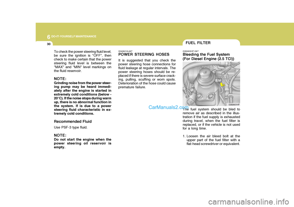
Bleeding the Fuel System (For Diesel Engine (2.5 TCI))
The fuel system should be bled to
remove air as described in the illus- tration if the fuel supply is exhausted during travel, when the fuel filter isreplaced, or if the vehicle is not used for a long time.
1. Loosen the air bleed bolt at the upper part of the fuel filter with a flat-head screwdriver or equivalent. G350A01HP
Page 255 of 291

6 DO-IT-YOURSELF MAINTENANCE
32
2. Operate the hand pump slowly 6 or
7 times in order to force the water out through the drain plug.
3. Tighten the drain plug when water no longer comes out.
4. Loosen the air bleed bolt and bleed the air.(Refer to "Bleeding the fuel sys-tem".)
5. Check to be sure that the warning lamp illuminates when the ignitionkey is turned to "ON", and that itgoes off when the engine is started.If in doubt, consult your nearestauthorized HYUNDAI dealer. G350A02HP
!
NOTE: It is recommended that water ac-
cumulated in the fuel filter should be removed by an authorized Hyundai dealer. G350B01HP-GAT
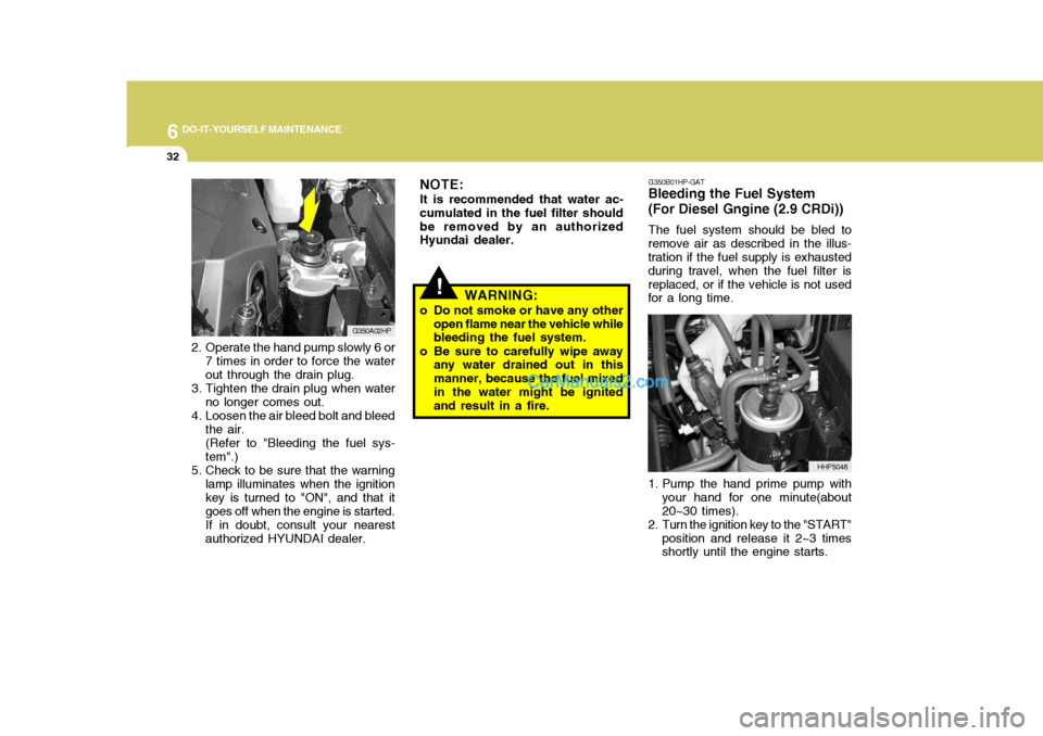
Bleeding the Fuel System (For Diesel Gngine (2.9 CRDi))
The fuel system should be bled to
remove air as described in the illus- tration if the fuel supply is exhausted during travel, when the fuel filter isreplaced, or if the vehicle is not used for a long time.
1. Pump the hand prime pump with your hand for one minute(about 20~30 times).
2. Turn the ignition key to the "START"
position and release it 2~3 times shortly until the engine starts. HHP5048
WARNING:
o Do not smoke or have any other open flame near the vehicle whilebleeding the fuel system.
o Be sure to carefully wipe away any water drained out in this manner, because the fuel mixedin the water might be ignited and result in a fire.
Page 256 of 291

6
DO-IT-YOURSELF MAINTENANCE
33
!
G300B02HP-GAT
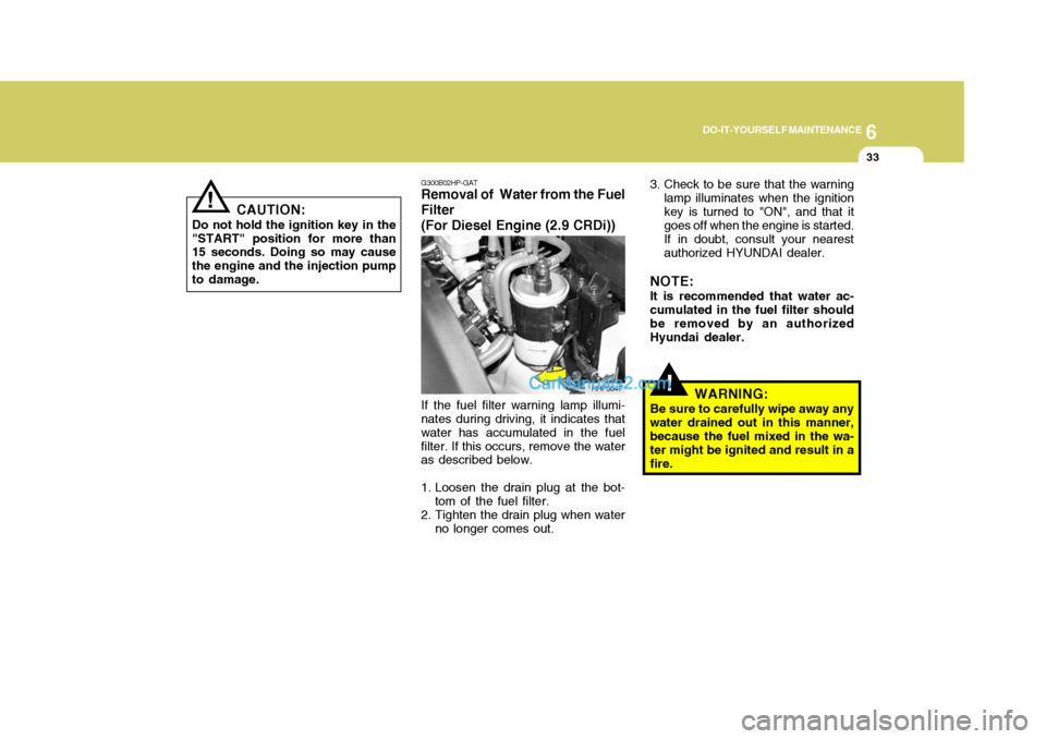
Removal of Water from the Fuel Filter (For Diesel Engine (2.9 CRDi))
If the fuel filter warning lamp illumi-
nates during driving, it indicates that water has accumulated in the fuelfilter. If this occurs, remove the water as described below.
1. Loosen the drain plug at the bot-
tom of the fuel filter.
2. Tighten the drain plug when water
no longer comes out. 3. Check to be sure that the warning
lamp illuminates when the ignition key is turned to "ON", and that it goes off when the engine is started. If in doubt, consult your nearest authorized HYUNDAI dealer.
NOTE: It is recommended that water ac- cumulated in the fuel filter should be removed by an authorizedHyundai dealer.
WARNING:
Be sure to carefully wipe away anywater drained out in this manner,because the fuel mixed in the wa- ter might be ignited and result in a fire.
HHP5047
!
CAUTION:
Do not hold the ignition key in the "START" position for more than 15 seconds. Doing so may cause the engine and the injection pumpto damage.
Page 262 of 291
6
DO-IT-YOURSELF MAINTENANCE
39
NO.1
NO. 2
NO. 3
NO.4
NO.5
NO. 6
NO. 7
NO. 8
NO. 9
NO. 10
NO. 11
NO. 12
DESCRIPTION
G200C01HP-GAT
Engine Compartment (#1)
G200C01HP
Note: Not all fuse panel descriptions in this manual may be applicable to your vehicle. It is accurate at the time of printing. When you inspect the fuse box on your vehicle, refer to the fuse box label. AMPERAGES(A)
100A
120A (DIESEL)
140A (GASOLINE)
50A 30A- -
20A 10A 15A -
10A10A CIRCUIT PROTECTED
Glow Relay (COVEC-F/EGR), Air Heater Relay (2.9 CRDi)
Engine Compartment Fuse & Relay Box #2,Generator
Inner Panel Fuse Box (Fuse 1,2,3,4,5),
Engine Compartment Fuse & Relay Box #1 (Fuse 8,9),
Fuel Heater Control Module (COVEC-F/EGR)
Generator, Ignition Switch--
Engine Control Relay (Diesel Engine), Main Control Relay(Gasoline Engine)
Horn Relay
Front Fog Lamp Relay-ECM (Diesel Engine), EGR Control ModuleECM (2.9 CRDi)
FUSIBLE LINK
FUSE
FUSE PANEL DESCRIP- TION
Gasoline Engine Diesel Engine
Page 265 of 291
6 DO-IT-YOURSELF MAINTENANCE
42
AMPERAGES(A)50A 30A 40A 40A 30A 40A 20A-
20A 10A 15A
NO. 1
NO. 2
NO. 3
NO. 4
NO. 5
NO. 6
NO. 7
NO. 8
NO. 9
DESCRIPTION
CIRCUIT PROTECTED
Power Connector(A,B), Engine Compartment Fuse and Relay Box #2
(Fuse 28,29), Inner Panel Fuse Box(Fuse 6,7,8, 9)
Start Relay, Ignition Switch
Condenser Fan Relay,
Engine Compartment Fuse and Relay Box #2(Fuse 14,15)ABS Control Module
Power Window Relay
Tail Lamp Relay,
Engine Compartment Fuse and Relay Box #2(Fuse 11,12)ABS Control Module-
Fuel Pump Relay, ECM, Ignition Failure Sensor
A/CON, TCM, ETACM, Data Link Connector, Siren,
Immobilizer Control Module
Interior Lamp, Map Lamp, Audio, Instrument Cluster,
Front Door Edge warning Lamp
FUSIBLE LINK
NO. 30
NO. 31
Page 287 of 291

10INDEX
4
Headlight Leveling Device S ystem ..........................1-100
Heating and Ventilation ............................................ 1-105
Air flow control ........................................... 1-106, 1-117
Temperature control .... .......................................... 1-108
High-Mounted Rear Stop Light ...................................1-95
Hood Release ............................................................ 1-97
Horn ........................................................................... 1-99
I Ignition Sw itch ............................................................. 2-3
Immobilizer S ystem ..................................................... 1-5
Limp Home Procedures ................................... 1-7, 1-9
Key ................................................................... 1-5, 1-8
Indicator and Warning Lights.................................... 1-58
Instrument Cluster and Indicator Li ghts................... 1-54
Instrument Panel Light Control (Rheo stat)............... 1-79
Interior Light .............................................................. 1-85
Intermittent Wiper ..................................................... 1-77
J Jump Starting .............................................................. 3-3
K
Key .............................................................................. 1-4 If you lose your keys ............................................. 3-17
Positions ................................................................... 2-4 L
Limited-Slip Differential
.............................................. 2-22
Luggage Compartment
Cargo Security Screen ........................................... 1-94
Light ........................................................................ 1-93
Net .......................................................................... 1-93
M Maintenance Intervals Explanation of scheduled maintenance items ......... 5-9
Maintenance under severe usage conditions .......... 5-8 Scheduled maintenance ........................................... 5-4
Service requ irements............................................... 5-2
Mirrors Day/night inside rearview ....... .................................1-90
Outside rearvi ew ..................................................... 1-88
Multimeter .................................................................. 1-69
Altimeter ................................................................. 1-70
Barometer ............................................................... 1-72
Digital Clock ........................................................... 1-72
Electrical azimuth compass ................................... 1-70
Relative altimeter .................................................... 1-71
O
Odometer ................................................................... 1-67
P Parking Brake ............................................................ 1-91
Part-time 4WD Opera tion ........................................... 2-14