2007 Hyundai Santa Fe check engine
[x] Cancel search: check enginePage 303 of 355
6
DO-IT-YOURSELF MAINTENANCE
17
CHECKING AND REPLACING
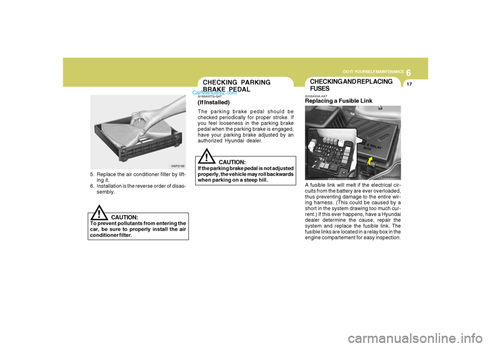
FUSESG200A03A-AATReplacing a Fusible LinkA fusible link will melt if the electrical cir-
cuits from the battery are ever overloaded,
thus preventing damage to the entire wir-
ing harness. (This could be caused by a
short in the system drawing too much cur-
rent.) If this ever happens, have a Hyundai
dealer determine the cause, repair the
system and replace the fusible link. The
fusible links are located in a relay box in the
engine compartement for easy inspection.
OCM054003
5. Replace the air conditioner filter by lift-
ing it.
6. Installation is the reverse order of disas-
sembly.
HNF2165
CAUTION:
To prevent pollutants from entering the
car, be sure to properly install the air
conditioner filter.
!
(If Installed)The parking brake pedal should be
checked periodically for proper stroke. If
you feel looseness in the parking brake
pedal when the parking brake is engaged,
have your parking brake adjusted by an
authorized Hyundai dealer.CHECKING PARKING
BRAKE PEDALG185A02TG-GAT
CAUTION:
If the parking brake pedal is not adjusted
properly, the vehicle may roll backwards
when parking on a steep hill.
!
Page 304 of 355
6
DO-IT-YOURSELF MAINTENANCE
18
!
CAUTION:
When replacing a fusible link, never use
anything but a new fusible link with the
same or lower amperage rating. Never
use a piece of wire or a higher-rated
fusible link. This could result in serious
damage and create a fire hazard.
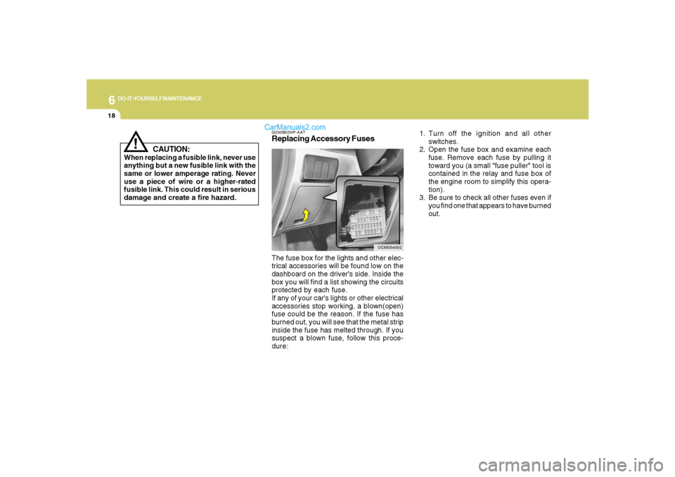
G200B02HP-AATReplacing Accessory Fuses
OCM054002
The fuse box for the lights and other elec-
trical accessories will be found low on the
dashboard on the driver's side. Inside the
box you will find a list showing the circuits
protected by each fuse.
If any of your car's lights or other electrical
accessories stop working, a blown(open)
fuse could be the reason. If the fuse has
burned out, you will see that the metal strip
inside the fuse has melted through. If you
suspect a blown fuse, follow this proce-
dure:1. Turn off the ignition and all other
switches.
2. Open the fuse box and examine each
fuse. Remove each fuse by pulling it
toward you (a small "fuse puller" tool is
contained in the relay and fuse box of
the engine room to simplify this opera-
tion).
3. Be sure to check all other fuses even if
you find one that appears to have burned
out.
Page 306 of 355
6
DO-IT-YOURSELF MAINTENANCE
20
G200C01CM-GATPower connectorNOTE:
o If the power connector is pulled out of
the fuse panel, the warning chime,
audio, clock and interior lamps, etc.,
will not operate. The following items
must be reset after replacement.
- Digital Clock
- Trip computer
- Automatic heating and cooling con-
trol system
- Audio
o Even though the power connector is
pulled out, the battery can still be
discharged by operation of the head-
lights or other electrical devices.
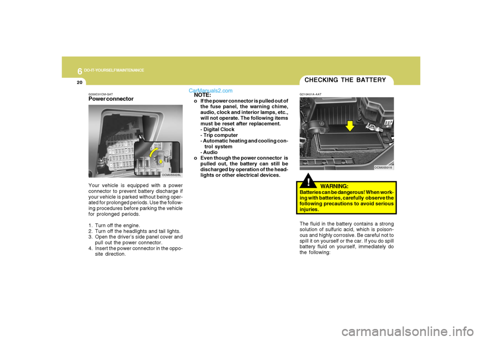
Your vehicle is equipped with a power
connector to prevent battery discharge if
your vehicle is parked without being oper-
ated for prolonged periods. Use the follow-
ing procedures before parking the vehicle
for prolonged periods.
1. Turn off the engine.
2. Turn off the headlights and tail lights.
3. Open the driver’s side panel cover and
pull out the power connector.
4. Insert the power connector in the oppo-
site direction.
OCM055026L
CHECKING THE BATTERY!
G210A01A-AAT
WARNING:
Batteries can be dangerous! When work-
ing with batteries, carefully observe the
following precautions to avoid serious
injuries.
The fluid in the battery contains a strong
solution of sulfuric acid, which is poison-
ous and highly corrosive. Be careful not to
spill it on yourself or the car. If you do spill
battery fluid on yourself, immediately do
the following:
OCM055016
Page 308 of 355
6
DO-IT-YOURSELF MAINTENANCE
22
If electrolyte gets on your skin,
thoroughly wash the contacted
area.
If you feel a pain or a burning
sensation, get medical atten-
tion immediately.
Wear eye protection when
charging or working near a bat-
tery.
Always provide ventilation
when working in an enclosed
space.
o When lifting a plastic-cased battery,
excessive pressure on the case may
cause battery acid to leak, resulting in
personal injury. Lift with a battery
carrier or with your hands on opposite
corners.
o Never attempt to charge the battery
when the battery cables are con-
nected.
o The electrical ignition system works
with high voltage.
Never touch these components with
the engine running or the ignition
switched on.
!
WARNING:
CHECKING ELECTRIC
COOLING FANS!
G220A01A-AAT
WARNING:
The cooling fan is controlled by engine
coolant temperature and may some-
times operate even when the engine is
not running. Use extreme caution when
working near the blades of the cooling
fan, so that you are not injured by a
rotating fan blade. As the engine coolant
temperature decreases the fan will au-
tomatically shut off. This is a normal
condition.
G220C01A-AATChecking Condenser Cooling FanThe condenser cooling fan should come
on automatically whenever the air condi-
tioning is in operation.G220B01A-AATChecking Engine Cooling FanThe engine cooling fan should come on
automatically if the engine coolant tem-
perature is high.
Page 309 of 355
6
DO-IT-YOURSELF MAINTENANCE
23
G240A01A-AATPower Steering HosesIt is suggested that you check the power
steering hose connections for fluid leak-
age at those intervals specified in the ve-
hicle maintenance schedule in Section 5.
The power steering hoses should be re-
placed if there is severe surface cracking,
pulling, scuffing or worn spots. Deteriora-
tion of the hose could cause premature
failure.NOTE:o Grinding noise from the power steer-
ing pump may be heard immediately
after the engine is started in extremely
cold conditions (below - 4°F). If the
noise stops during warm up, there is
no abnormal function in the system. It
is due to a power steering fluid char-
acteristic in extremely cold condi-
tions.
oDo not start the engine when the power
steering oil reservoir is empty.
POWER STEERING FLUID
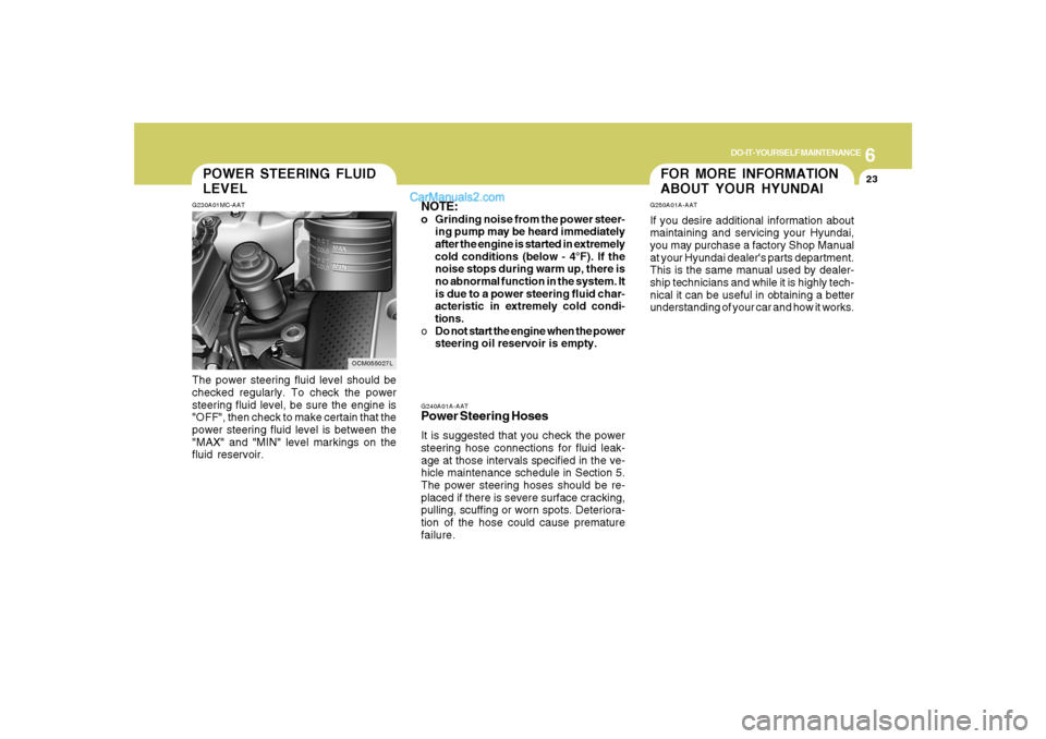
LEVELG230A01MC-AATThe power steering fluid level should be
checked regularly. To check the power
steering fluid level, be sure the engine is
"OFF", then check to make certain that the
power steering fluid level is between the
"MAX" and "MIN" level markings on the
fluid reservoir.
OCM055027L
FOR MORE INFORMATION
ABOUT YOUR HYUNDAIG250A01A-AATIf you desire additional information about
maintaining and servicing your Hyundai,
you may purchase a factory Shop Manual
at your Hyundai dealer's parts department.
This is the same manual used by dealer-
ship technicians and while it is highly tech-
nical it can be useful in obtaining a better
understanding of your car and how it works.
Page 310 of 355
6
DO-IT-YOURSELF MAINTENANCE
24
REPLACEMENT OF LIGHT
BULBSG260A01CM-AATBefore attempting to replace a light bulb,
be sure the switch is turned to the "OFF"
position.
The next paragraph shows how to reach
the light bulbs so they may be changed. Be
sure to replace the burned-out bulb with
one of the same number and wattage
rating.
CAUTION:
o Keep the lamps out of contact with
petroleum products, such as oil, gaso-
line, etc.
o After heavy, driving rain or washing,
headlight and taillight lenses could
appear frosty. This condition is
caused by the temperature difference
between the lamp inside and outside.
This is similar to the condensation on
your windows inside your vehicle
during the rain and doesn’t indicate a
problem with your vehicle. If the water
leaks into the lamp bulb circuitry, have
the vehicle checked by an Authorized
Hyundai Dealer.
!
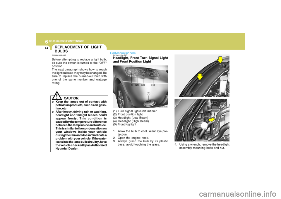
G270A01CM-GATHeadlight, Front Turn Signal Light
and Front Position Light(1) Turn signal light/Side marker
(2) Front position light
(3) Headlight (Low Beam)
(4) Headlight (High Beam)
(5) Front fog light
1. Allow the bulb to cool. Wear eye pro-
tection.
2. Open the engine hood.
3. Always grasp the bulb by its plastic
base, avoid touching the glass.
OCM055020
(1)
(2) (3) (4)
(5)
OCM055008L
4. Using a wrench, remove the headlight
assembly mounting bolts and nut.
OCM055021L
Page 318 of 355

6
DO-IT-YOURSELF MAINTENANCE
32
FUSE PANEL DESCRIPTIONG200C01CM-AATEngine Compartment
OCM055023N
Note:Not all fuse panel descriptions in this manual may be applicable to your vehicle. It is accurate at the time of printing. When you
inspect the fuse box on your vehicle, refer to the fuse box label.
FUSE RATING
150A
10A
30A
40A
50A
40A
40A
20A
15A
40A
15A
20A
15A
40A
30A
15A
10ACIRCUIT PROTECTED
GENERATOR
A/CON RELAY
RR HTD RELAY
I/PJUNCTION BOX
I/PJUNCTION BOX
I/PJUNCTION BOX
ABS CONTROL MODULE, ESC CONTROL MODULE, MULTIPURPOSE CHECK
CONNECTOR
ABS CONTROL MODULE, ESC CONTROL MODULE, MULTIPURPOSE CHECK
CONNECTOR
DEICER RELAY
ENGINE CONTROL RELAY
HORN RELAY
IGNITION COIL #1~#6(GASOLINE), CONDENSOR(GASOLINE)
PURGE CONTROL SOLENOID VALVE(GASOLINE), VARIABLE INTAKE MANIFOLD
VALVE(GASOLINE), PCM(GASOLINE), OIL CONTROL VALVE(GASOLINE)
RAD FAN RELAY
CON FAN #1 RELAY, CON FAN #2 RELAY
MASS AIR FLOW SENSOR(GASOLINE), OXYGEN SENSOR #1~#4(GASOLINE),
PCM(GASOLINE)
IMMOBILIZER MODULE, INJECTOR #1~#6(GASOLINE), PCM(GASOLINE), A/
CON RELAY, FUEL PUMP RELAY
ALT
A/CON
RR HTD
BLR
BATT
P/WDW
ESC #1
ESC #2
DEICER
ECU MAIN
HORN
IG COIL
SENSOR #3
RAD FAN
CON FAN
SENSOR #2
SENSOR #1FUSE
Page 350 of 355

10
INDEX
3
Corrosion protection
Cleaning the interior....................................................................... 4-5
Protecting your Hyundai from corrosion....................................... 4-2
Washing and waxing...................................................................... 4-4
Cruise Control................................................................................1-120
D
Defrosting / Defogging ...................................................................1-133
Door
Central door lock............................................................................ 1-9
Door locks...................................................................................... 1-7
Front door edge warning light ...................................................1-119
Drink Holder ......................................................................................1-88
Driving
Driving for economy .....................................................................2-23
Smooth cornering.........................................................................2-24
Winter driving...............................................................................2-24
E
Emission Control System ................................................................... 7-2
Engine
Before starting the engine .............................................................. 2-4
Compartment................................................................................. 6-2
Coolant........................................................................................... 6-7
Coolant temperature gauge .........................................................1-71
If the engine overheats .................................................................. 3-4
Number........................................................................................... 8-2
Oil ................................................................................................... 6-5
Starting........................................................................................... 2-6
Engine Exhaust Can Be Dangerous .................................................. 2-2F
Fan Speed Control.........................................................................1-126
Floor Mat Anchor ...........................................................................1-116
Fog Light
Front.............................................................................................1-82
Front Seats
Adjustable front seats ..................................................................1-16
Adjustable headrests...................................................................1-18
Adjusting seat forward and rearward ..........................................1-16
Adjusting seatback angle .............................................................1-17
Fuel
Capacity......................................................................................... 9-2
Gauge...........................................................................................1-71
Recommendations......................................................................... 1-2
Fuel Filler Lid
Remote release.........................................................................1-113
Full-time AWD Operation..................................................................
2-17
Fuses ................................................................................................6-17
Fuse panel description......................................................................6-32
G
General Checks.................................................................................. 6-4
Glove Box..........................................................................................1-95
H
Hazard Warning System ..................................................................1-83
Heating and Cooling Control..........................................................1-125
Heating and Ventilation
Air flow control...........................................................................1-127