Page 304 of 355

6
DO-IT-YOURSELF MAINTENANCE
18
!
CAUTION:
When replacing a fusible link, never use
anything but a new fusible link with the
same or lower amperage rating. Never
use a piece of wire or a higher-rated
fusible link. This could result in serious
damage and create a fire hazard.
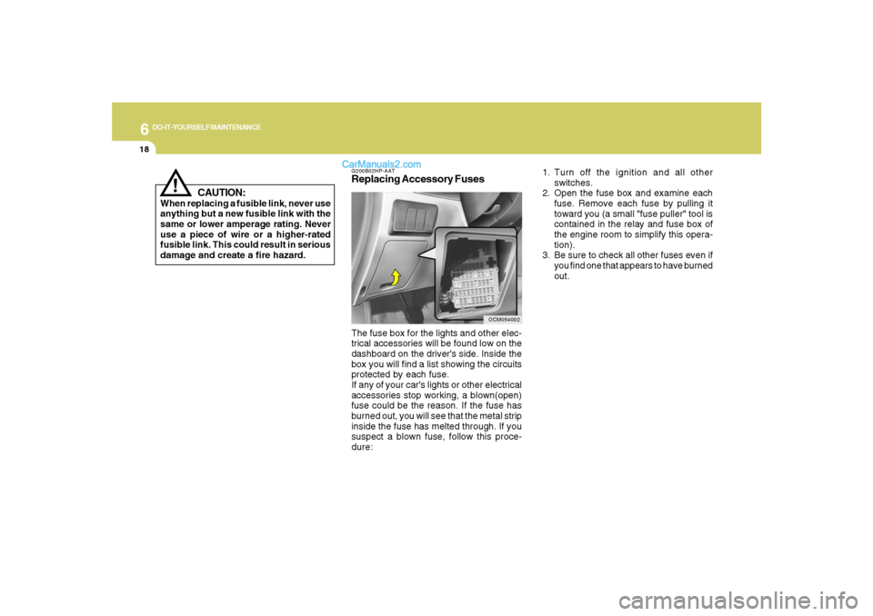
G200B02HP-AATReplacing Accessory Fuses
OCM054002
The fuse box for the lights and other elec-
trical accessories will be found low on the
dashboard on the driver's side. Inside the
box you will find a list showing the circuits
protected by each fuse.
If any of your car's lights or other electrical
accessories stop working, a blown(open)
fuse could be the reason. If the fuse has
burned out, you will see that the metal strip
inside the fuse has melted through. If you
suspect a blown fuse, follow this proce-
dure:1. Turn off the ignition and all other
switches.
2. Open the fuse box and examine each
fuse. Remove each fuse by pulling it
toward you (a small "fuse puller" tool is
contained in the relay and fuse box of
the engine room to simplify this opera-
tion).
3. Be sure to check all other fuses even if
you find one that appears to have burned
out.
Page 309 of 355

6
DO-IT-YOURSELF MAINTENANCE
23
G240A01A-AATPower Steering HosesIt is suggested that you check the power
steering hose connections for fluid leak-
age at those intervals specified in the ve-
hicle maintenance schedule in Section 5.
The power steering hoses should be re-
placed if there is severe surface cracking,
pulling, scuffing or worn spots. Deteriora-
tion of the hose could cause premature
failure.NOTE:o Grinding noise from the power steer-
ing pump may be heard immediately
after the engine is started in extremely
cold conditions (below - 4°F). If the
noise stops during warm up, there is
no abnormal function in the system. It
is due to a power steering fluid char-
acteristic in extremely cold condi-
tions.
oDo not start the engine when the power
steering oil reservoir is empty.
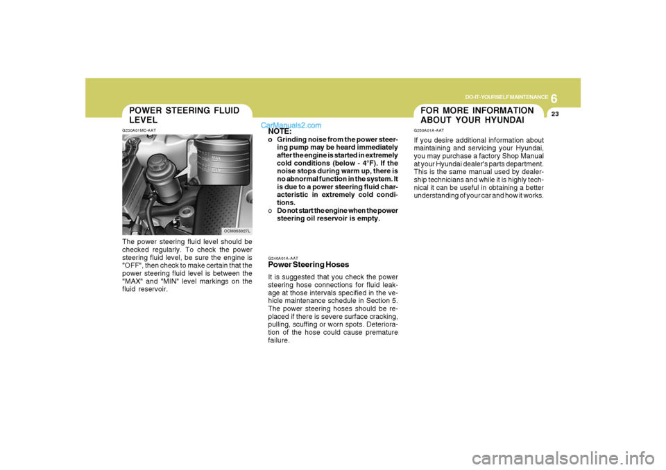
POWER STEERING FLUID
LEVELG230A01MC-AATThe power steering fluid level should be
checked regularly. To check the power
steering fluid level, be sure the engine is
"OFF", then check to make certain that the
power steering fluid level is between the
"MAX" and "MIN" level markings on the
fluid reservoir.
OCM055027L
FOR MORE INFORMATION
ABOUT YOUR HYUNDAIG250A01A-AATIf you desire additional information about
maintaining and servicing your Hyundai,
you may purchase a factory Shop Manual
at your Hyundai dealer's parts department.
This is the same manual used by dealer-
ship technicians and while it is highly tech-
nical it can be useful in obtaining a better
understanding of your car and how it works.
Page 318 of 355

6
DO-IT-YOURSELF MAINTENANCE
32
FUSE PANEL DESCRIPTIONG200C01CM-AATEngine Compartment
OCM055023N
Note:Not all fuse panel descriptions in this manual may be applicable to your vehicle. It is accurate at the time of printing. When you
inspect the fuse box on your vehicle, refer to the fuse box label.
FUSE RATING
150A
10A
30A
40A
50A
40A
40A
20A
15A
40A
15A
20A
15A
40A
30A
15A
10ACIRCUIT PROTECTED
GENERATOR
A/CON RELAY
RR HTD RELAY
I/PJUNCTION BOX
I/PJUNCTION BOX
I/PJUNCTION BOX
ABS CONTROL MODULE, ESC CONTROL MODULE, MULTIPURPOSE CHECK
CONNECTOR
ABS CONTROL MODULE, ESC CONTROL MODULE, MULTIPURPOSE CHECK
CONNECTOR
DEICER RELAY
ENGINE CONTROL RELAY
HORN RELAY
IGNITION COIL #1~#6(GASOLINE), CONDENSOR(GASOLINE)
PURGE CONTROL SOLENOID VALVE(GASOLINE), VARIABLE INTAKE MANIFOLD
VALVE(GASOLINE), PCM(GASOLINE), OIL CONTROL VALVE(GASOLINE)
RAD FAN RELAY
CON FAN #1 RELAY, CON FAN #2 RELAY
MASS AIR FLOW SENSOR(GASOLINE), OXYGEN SENSOR #1~#4(GASOLINE),
PCM(GASOLINE)
IMMOBILIZER MODULE, INJECTOR #1~#6(GASOLINE), PCM(GASOLINE), A/
CON RELAY, FUEL PUMP RELAY
ALT
A/CON
RR HTD
BLR
BATT
P/WDW
ESC #1
ESC #2
DEICER
ECU MAIN
HORN
IG COIL
SENSOR #3
RAD FAN
CON FAN
SENSOR #2
SENSOR #1FUSE
Page 323 of 355

7
EMISSION CONTROL SYSTEMS2
EMISSION CONTROL SYSTEM
H010B01A-AAT1. Crankcase Emission Control
SystemThe positive crankcase ventilation system
is employed to prevent air pollution caused
by blow-by gases being emitted from the
crankcase. This system supplies filtered
air to the crankcase through the air intake
hose. Inside the crankcase, the fresh air
mixes with blow-by gases, which then pass
through the PCV valve and into the induc-
tion system.
H010A01NF-AATYour Hyundai is equipped with an emis-
sion control system to meet all emission
regulations.
There are three emission control systems
which are as follows.
(1) Crankcase emission control system
(2) Evaporative emission control system
(3) Exhaust emission control system
In order to assure the proper function of the
emission control systems, it is recom-
mended that you have your car inspected
and maintained by an authorized Hyundai
dealer in accordance with the maintenance
schedule in this manual.
Caution for the Inspection and Mainte-
nance Test (With Electronic Stability
Control (ESC) system)
o To prevent the vehicle from misfiring
during dynamometer testing, turn the
Electronic Stability Control (ESC) sys-
tem off by pressing the ESC switch.
o After dynamometer testing is com-
pleted, turn the ESC system back on
by pressing the ESC switch again.
H010C01S-AAT2. Evaporative Emission Control (In-
cluding ORVR: Onboard Refuel-
ing Vapor Recovery) SystemThe Evaporative Emission Control Sys-
tem is designed to prevent fuel vapors from
escaping into the atmosphere.
(The ORVR system is designed to allow
the vapors from the fuel tank to be loaded
into a canister while refueling at the gas
station, preventing the escape of fuel va-
pors into the atmosphere.)CanisterFuel vapors generated inside the fuel tank
are absorbed and stored in the canister.
When the engine is running, the fuel va-
pors absorbed in the canister are drawn
into the induction system through the purge
control solenoid valve.
Cmhma-7.p653/17/2006, 10:29 AM 2
Page 324 of 355

7
EMISSION CONTROL SYSTEMS
3
H010D01A-AAT3. Exhaust Emission Control Sys-
temThe Exhaust Emission Control System is a
highly effective system which controls ex-
haust emissions while maintaining good
vehicle performace.Purge Control Solenoid Valve (PCSV)The purge control solenoid valve is con-
trolled by the Engine Control Module
(ECM); when the engine coolant tempera-
ture is low during idling, the PCSV closes
so that evaporated fuel is not taken into the
engine. After the engine warms-up during
ordinary driving, the PCSV opens to intro-
duce evaporated fuel to the engine.
CATALYTIC CONVERTER
!
WARNING:
o Use unleaded fuel only.
o Maintain the engine in good operating
condition. Extremely high catalytic
converter temperatures can result
from improper operation of the elec-
trical, ignition or multiport electronic
fuel injection.
o If your engine stalls, pings, knocks, or
is hard to start, have your Hyundai
dealer inspect and repair the problem
as soon as possible.
o Avoid driving with a very low fuel level.
Running out of gasoline may cause
the engine to misfire and result in
damage to the catalytic converter.
o Avoid idling the engine for periods
longer than 10 minutes.
o The vehicle should not be pushed or
pulled to get started. This may cause
the catalytic converter to overheat
and create a fire hazard.
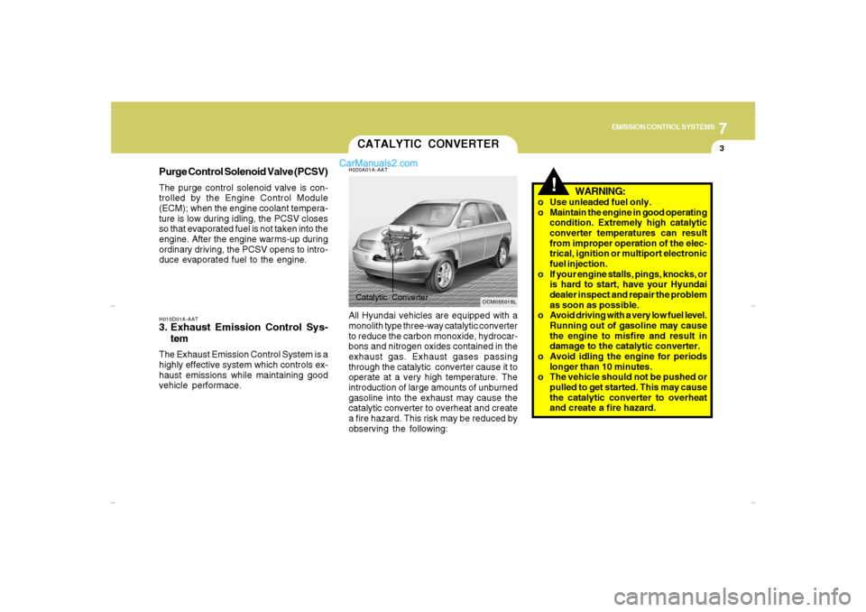
H020A01A-AATAll Hyundai vehicles are equipped with a
monolith type three-way catalytic converter
to reduce the carbon monoxide, hydrocar-
bons and nitrogen oxides contained in the
exhaust gas. Exhaust gases passing
through the catalytic converter cause it to
operate at a very high temperature. The
introduction of large amounts of unburned
gasoline into the exhaust may cause the
catalytic converter to overheat and create
a fire hazard. This risk may be reduced by
observing the following:
OCM055018L
Catalytic Converter
Cmhma-7.p653/17/2006, 10:29 AM 3
Page 344 of 355
9
Dimensions................................................................... 9-2
Engine...........................................................................9-3
Lubrication Chart ........................................................... 9-4
VEHICLE SPECIFICATIONS
9
Cmhma-9.p653/17/2006, 10:30 AM 1
Page 345 of 355
9
VEHICLE SPECIFICATIONS2
J050A01CM-AATBRAKE
Dual hydraulic with brake booster
Ventilated disc
Disc type
Cable operated on rear wheel Type
Front brake type
Rear brake type
Parking brake
J040A01CM-AATELECTRICALItem
Battery
Generator2.7L Gasoline
3.3L Gasoline
CMF 68L
130A (13.5 V) 183.1 (4650)
184.1 (4675)
74.4 (1890)
67.9 (1725)
70.7 (1795)
106.3 (2700)
63.6 (1615)
63.8 (1620)
J010A01CM-AATDIMENSIONSOverall length
Overall width
Overall height
Wheel base
Wheel tread
in. (mm)
Standard
Option
Standard
with Roof Rack
Front
Rear
J060A01CM-AATFUEL SYSTEM
Engine
2.7L / 3.3LFuel tank capacity
19.8 us.gal (16.5 imp.gal, 75 liter)
J030A01CM-AATTIRE
Full
Temporary
Size Type
Inflation pressure kPa (psi)
235/70R16
235/60R18
T165/90R17NORMAL
LOADMAXIMUM
LOAD
220(32)
420(60) 210(30)
420(60)
Cmhma-9.p653/17/2006, 10:30 AM 2
Page 346 of 355
9
VEHICLE SPECIFICATIONS
3
ENGINE
2.7 L
6-Cyl., V-type DOHC
3.41 x 2.95 (86.7 x 75)
162.0 (2656)
2 - 3 - 4 - 5 - 6 - 1
Auto lash
Auto lash
680 ± 100
BTDC 7° ± 5° ITEMS
Engine Type
Bore x Stroke in. (mm)
Displacement cu.in. (cc)
Firing order
Valve clearance
(warm engine)
Idle speed (rpm)
Ignition timing (at idle)3.3 L
6-Cyl., V-type DOHC
3.62 x 3.29 (92 x 83.8)
203.9 (3342)
1 - 2 - 3 - 4 - 5 - 6
0.28
0.35
620 ± 100
BTDC 10° ± 5°
J070A03CM-AAT
Intake
ExhaustGASOLINE
Cmhma-9.p653/17/2006, 10:30 AM 3