2007 Hyundai Santa Fe fuel
[x] Cancel search: fuelPage 280 of 355

5
VEHICLE MAINTENANCE REQUIREMENTS4
SCHEDULED MAINTENANCEF030B02O-AATR :Replace I : Inspect and, after Inspection, clean, adjust, repair or replace if necessary.
DESCRIPTION
EMISSION CONTROL ITEMS
ENGINE OIL AND FILTER
FUEL FILTER
FUEL LINES, FUEL HOSES AND CONNECTIONS
VACUUM HOSES
CRANKCASE VENTILATION HOSE
VAPOR HOSE AND FUEL FILLER CAP
AIR CLEANER FILTER
FUEL TANK AIR FILTER
SPARK PLUGS (IRIDIUM COATED) *
1
VALVE CLEARANCESee Note *
2
No.
1
2
3
4
5
6
7
8
9
10MILES X 1000
KILOMETERS X 1000
MONTHS7.5
12
6
R
I15
24
12
R
I
I
I22.5
36
18
R
I30
48
24
R
I
I
I
R
R37.5
60
30
R
I45
72
36
R
I
I
I52.5
84
42
R
I
I60
96
48
R
R
I
I
I
R
R67.5
108
54
R
I75
120
60
R
I
I
I82.5
132
66
R
I90
144
72
R
I
I
I
R
R97.5
156
78
R
I
R105
168
84
R
I
I
I
I112.5
180
90
R
I120
192
96
R
R
I
I
I
R
R127.5
204
102
R
I135
216
108
R
I
I
I142.5
228
114
R
I150
240
120
R
I
I
I
R
R
F030A01A-AATThe following maintenance services must be performed to ensure good emission control and performance. Keep receipts for all vehicle
emission services to protect your warranty. Where both mileage and time are shown, the frequency of service is determined by whichever
occurs first.
2.7 ENGINE
3.3 ENGINE
EVERY 7,500 MILES (12,000 KM) OR 12 MONTHS : "R"
INSPECT AND ADJUST EVERY 60,000 MILES (96,000 KM) OR 48 MONTHS
Note : *1. Spark plugs should be long-reach type when replaced (2.7 only)
*2. Inspect for excessive tappet noise and/or engine vibration and adjust if necessary.
Page 283 of 355

5
VEHICLE MAINTENANCE REQUIREMENTS
7
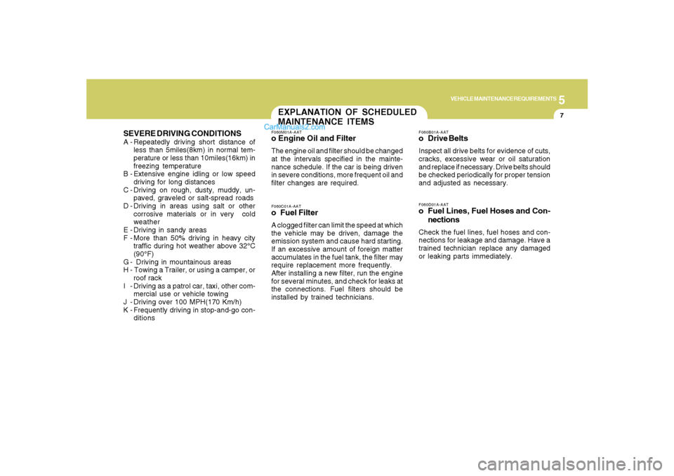
SEVERE DRIVING CONDITIONSA - Repeatedly driving short distance of
less than 5miles(8km) in normal tem-
perature or less than 10miles(16km) in
freezing temperature
B - Extensive engine idling or low speed
driving for long distances
C - Driving on rough, dusty, muddy, un-
paved, graveled or salt-spread roads
D - Driving in areas using salt or other
corrosive materials or in very cold
weather
E - Driving in sandy areas
F - More than 50% driving in heavy city
traffic during hot weather above 32°C
(90°F)
G - Driving in mountainous areas
H - Towing a Trailer, or using a camper, or
roof rack
I - Driving as a patrol car, taxi, other com-
mercial use or vehicle towing
J - Driving over 100 MPH(170 Km/h)
K - Frequently driving in stop-and-go con-
ditions
F060D01A-AATo Fuel Lines, Fuel Hoses and Con-
nectionsCheck the fuel lines, fuel hoses and con-
nections for leakage and damage. Have a
trained technician replace any damaged
or leaking parts immediately.F060B01A-AATo Drive BeltsInspect all drive belts for evidence of cuts,
cracks, excessive wear or oil saturation
and replace if necessary. Drive belts should
be checked periodically for proper tension
and adjusted as necessary.
F060M01A-AATo Engine Oil and FilterThe engine oil and filter should be changed
at the intervals specified in the mainte-
nance schedule. If the car is being driven
in severe conditions, more frequent oil and
filter changes are required.F060C01A-AATo Fuel FilterA clogged filter can limit the speed at which
the vehicle may be driven, damage the
emission system and cause hard starting.
If an excessive amount of foreign matter
accumulates in the fuel tank, the filter may
require replacement more frequently.
After installing a new filter, run the engine
for several minutes, and check for leaks at
the connections. Fuel filters should be
installed by trained technicians.EXPLANATION OF SCHEDULED
MAINTENANCE ITEMS
Page 284 of 355

5
VEHICLE MAINTENANCE REQUIREMENTS8
F070C01A-AATo CoolantThe coolant should be changed at the
intervals specified in the maintenance
schedule.F060E01A-AATo Timing Belt (2.7L V6 only)Inspect all parts related to the timing belt for
damage and deformation. Replace any
damaged parts immediately.F060J01A-AATo Spark PlugsMake sure to install new spark plugs of the
correct heat range.F060H01A-AATo Air Cleaner FilterA Genuine Hyundai air cleaner filter is
recommended when the filter is replaced.
F060G01A-AATo Vapor Hose and Fuel Filler CapThe vapor hose and fuel filler cap should
be inspected at those intervals specified in
the maintenance schedule. Make sure that
a new vapor hose or fuel filler cap is cor-
rectly replaced.F065F01O-AATo Crankcase Ventilation HoseInspect the surface of hose for evidence of
heat and/or mechanical damage. Hard
and brittle rubber, cracking, tears, cuts,
abrasions, and excessive swelling indi-
cate deterioration. Particular attention
should be paid to examine that hose sur-
face nearest to high heat sources, such as
the exhaust manifold.
Inspect the hose routing to assure that the
hose does not come in contact with any
heat source, sharp edges or moving com-
ponent which might cause heat damage or
mechanical wear. Inspect all hose con-
nections, such as clamps and couplings,
to make sure they are secure, and that no
leaks are present. Hose should be re-
placed immediately if there is any evi-
dence of deterioration or damage.
F060F01O-AATo Vacuum HosesInspect the surface of hoses for evidence
of heat and/or mechanical damage. Hard
and brittle rubber, cracking, tears, cuts,
abrasions, and excessive swelling indi-
cate deterioration. Particular attention
should be paid to examine those hose
surfaces nearest to high heat sources,
such as the exhaust manifold.
Inspect the hose routing to assure that the
hoses do not come in contact with any heat
source, sharp edges or moving compo-
nent which might cause heat damage or
mechanical wear. Inspect all hose con-
nections, such as clamps and couplings,
to make sure they are secure, and that no
leaks are present. Hoses should be re-
placed immediately if there is any evi-
dence of deterioration or damage.
Page 291 of 355

6
DO-IT-YOURSELF MAINTENANCE
5
CHECKING THE ENGINE
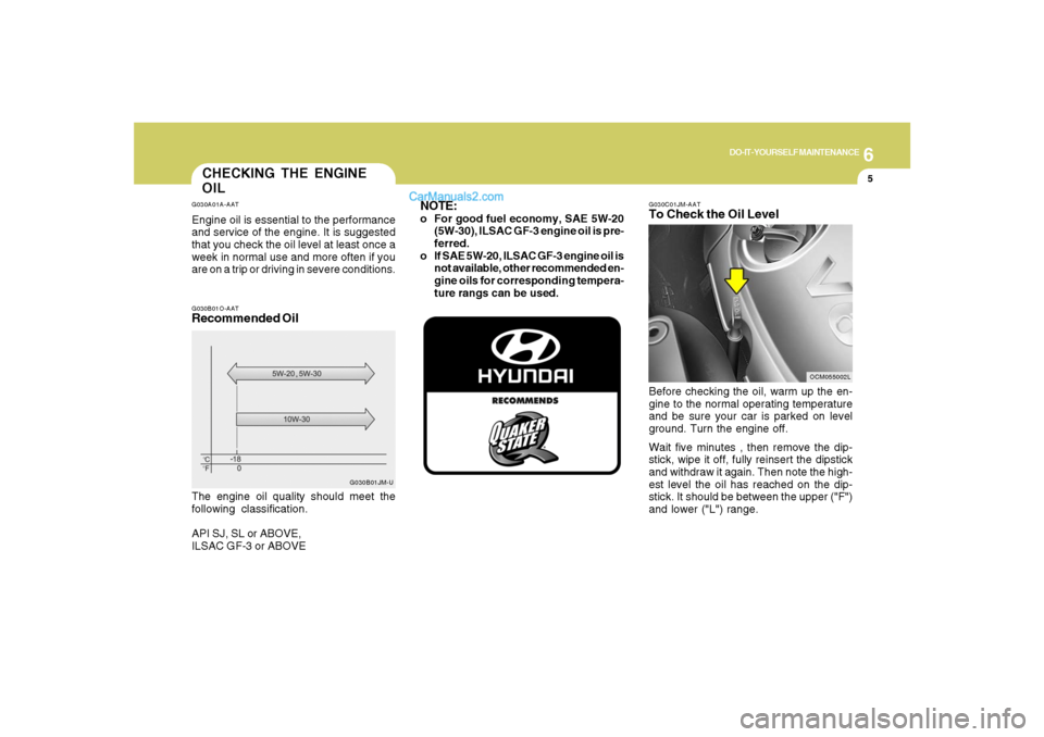
OILG030A01A-AATEngine oil is essential to the performance
and service of the engine. It is suggested
that you check the oil level at least once a
week in normal use and more often if you
are on a trip or driving in severe conditions.
G030C01JM-AATTo Check the Oil LevelBefore checking the oil, warm up the en-
gine to the normal operating temperature
and be sure your car is parked on level
ground. Turn the engine off.
Wait five minutes , then remove the dip-
stick, wipe it off, fully reinsert the dipstick
and withdraw it again. Then note the high-
est level the oil has reached on the dip-
stick. It should be between the upper ("F")
and lower ("L") range.
OCM055002L G030B01O-AAT
Recommended OilThe engine oil quality should meet the
following classification.
API SJ, SL or ABOVE,
ILSAC GF-3 or ABOVE
G030B01JM-U
NOTE:o For good fuel economy, SAE 5W-20
(5W-30), ILSAC GF-3 engine oil is pre-
ferred.
o If SAE 5W-20, ILSAC GF-3 engine oil is
not available, other recommended en-
gine oils for corresponding tempera-
ture rangs can be used.
Page 318 of 355

6
DO-IT-YOURSELF MAINTENANCE
32
FUSE PANEL DESCRIPTIONG200C01CM-AATEngine Compartment
OCM055023N
Note:Not all fuse panel descriptions in this manual may be applicable to your vehicle. It is accurate at the time of printing. When you
inspect the fuse box on your vehicle, refer to the fuse box label.
FUSE RATING
150A
10A
30A
40A
50A
40A
40A
20A
15A
40A
15A
20A
15A
40A
30A
15A
10ACIRCUIT PROTECTED
GENERATOR
A/CON RELAY
RR HTD RELAY
I/PJUNCTION BOX
I/PJUNCTION BOX
I/PJUNCTION BOX
ABS CONTROL MODULE, ESC CONTROL MODULE, MULTIPURPOSE CHECK
CONNECTOR
ABS CONTROL MODULE, ESC CONTROL MODULE, MULTIPURPOSE CHECK
CONNECTOR
DEICER RELAY
ENGINE CONTROL RELAY
HORN RELAY
IGNITION COIL #1~#6(GASOLINE), CONDENSOR(GASOLINE)
PURGE CONTROL SOLENOID VALVE(GASOLINE), VARIABLE INTAKE MANIFOLD
VALVE(GASOLINE), PCM(GASOLINE), OIL CONTROL VALVE(GASOLINE)
RAD FAN RELAY
CON FAN #1 RELAY, CON FAN #2 RELAY
MASS AIR FLOW SENSOR(GASOLINE), OXYGEN SENSOR #1~#4(GASOLINE),
PCM(GASOLINE)
IMMOBILIZER MODULE, INJECTOR #1~#6(GASOLINE), PCM(GASOLINE), A/
CON RELAY, FUEL PUMP RELAY
ALT
A/CON
RR HTD
BLR
BATT
P/WDW
ESC #1
ESC #2
DEICER
ECU MAIN
HORN
IG COIL
SENSOR #3
RAD FAN
CON FAN
SENSOR #2
SENSOR #1FUSE
Page 319 of 355

6
DO-IT-YOURSELF MAINTENANCE
33
FUSE RATING
15A
15A
15A
10A
10A
25A
20A
10A
40A
40A
50A
20A
15A
10A
10A
10A
10A
10A
10A
10A
10A
15A
20A
25A
30ACIRCUIT PROTECTED
FUEL PUMP RELAY
H/LP LO LH RELAY
H/LP LO RH RELAY
FR FOG RELAY
I/P JUNCTION BOX
FR WIPER RELAY, RAIN SNSR RELAY, FRONT WIPER MOTOR, MULTIFUNCTION SWITCH
H/LP HI RELAY
HEAD LAMP, INSTRUMENT CLUSTER
IGNITION SWITCH
IGNITION SWITCH, START RELAY
I/P JUNCTION BOX
ATM RELAY(GASOLINE), AWD ECM
PCM(GASOLINE)
GENERATOR
VEHICLE SPEED SENSOR, PCM(GASOLINE), SEMI ACTIVE CONTROL MODULE(GASOLINE)
CON FAN #1 RELAY, CON FAN #2 RELAY
INPUT SPEED SENSOR, OUTPUT SPEED SENSOR, TRANSAXLE RANGE SWITCH, BACK-UP LAMP SWITCH
ABS CONTROL MODULE, ESC CONTROL MODULE, YAW RATE SENSOR, AWD ECM, STOP LAMP SWITCH(GASOLINE), MULTIPURPOSE
CHECK CONNECTOR
REAR COMBINATION LAMP LH, POSITION LAMP LH
REAR COMBINATION LAMP RH, POSITION LAMP RH
GLOVE BOX CAMP, ICM RELAY BOX
-
-
-
-
-
FUEL PUMP
H/LP LO LH
H/LP LO RH
FR FOG
H/LP
FR WIPER
H/LP HI
H/LP HI IND
IGN #1
IGN #2
BATT
AT M
TCU
ALT DSL
ECU
COOLING
B/UP UP
ESC
TAIL LH
TAIL RH
SPARE
SPARE
SPARE
SPARE
SPAREFUSE
Page 321 of 355

6
DO-IT-YOURSELF MAINTENANCE
35
FUSE RATING
30A
25A
30A
15A
10A
20A
10A
20A
15A
15A
10A
10A
10A
15A
15A
15A
30A
30A
30A
10A
10A
15A
10A
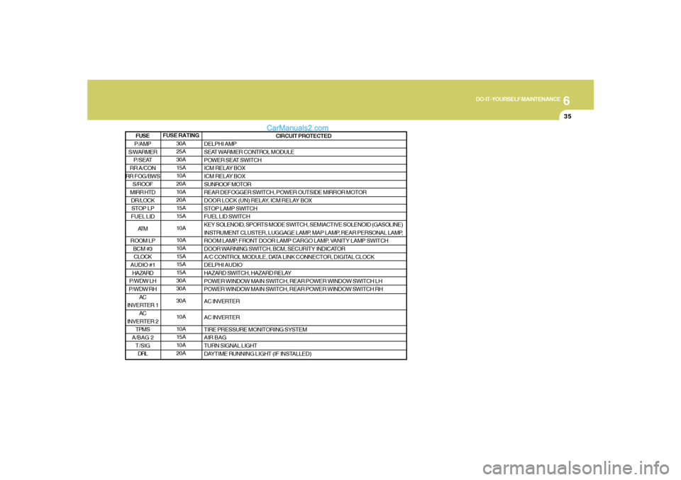
20ACIRCUIT PROTECTED
DELPHI AMP
SEAT WARMER CONTROL MODULE
POWER SEAT SWITCH
ICM RELAY BOX
ICM RELAY BOX
SUNROOF MOTOR
REAR DEFOGGER SWITCH, POWER OUTSIDE MIRROR MOTOR
DOOR LOCK (UN) RELAY, ICM RELAY BOX
STOP LAMP SWITCH
FUEL LID SWITCH
KEY SOLENOID, SPORTS MODE SWITCH, SEMIACTIVE SOLENOID (GASOLINE)
INSTRUMENT CLUSTER, LUGGAGE LAMP, MAP LAMP, REAR PERSONAL LAMP,
ROOM LAMP, FRONT DOOR LAMP CARGO LAMP, VANITY LAMP SWITCH
DOOR WARNING SWITCH, BCM, SECURITY INDICATOR
A/C CONTROL MODULE, DATA LINK CONNECTOR, DIGITAL CLOCK
DELPHI AUDIO
HAZARD SWITCH, HAZARD RELAY
POWER WINDOW MAIN SWITCH, REAR POWER WINDOW SWITCH LH
POWER WINDOW MAIN SWITCH, REAR POWER WINDOW SWITCH RH
AC INVERTER
AC INVERTER
TIRE PRESSURE MONITORING SYSTEM
AIR BAG
TURN SIGNAL LIGHT
DAYTIME RUNNING LIGHT (IF INSTALLED)
P/AMP
S/WARMER
P/SEAT
RR A/CON
RR FOG/BWS
S/ROOF
MIRR HTD
DR/LOCK
STOP LP
FUEL LID
AT M
ROOM LP
BCM #3
CLOCK
AUDIO #1
HAZARD
P/WDW LH
P/WDW RH
AC
INVERTER 1
AC
INVERTER 2
TPMS
A/BAG 2
T/SIG
DRLFUSE
Page 323 of 355

7
EMISSION CONTROL SYSTEMS2
EMISSION CONTROL SYSTEM
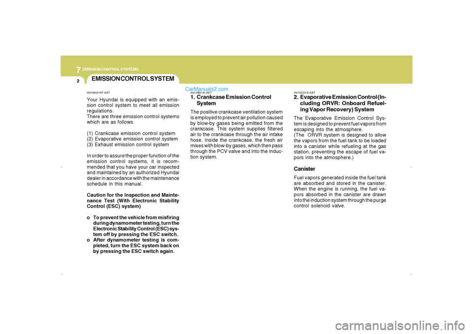
H010B01A-AAT1. Crankcase Emission Control
SystemThe positive crankcase ventilation system
is employed to prevent air pollution caused
by blow-by gases being emitted from the
crankcase. This system supplies filtered
air to the crankcase through the air intake
hose. Inside the crankcase, the fresh air
mixes with blow-by gases, which then pass
through the PCV valve and into the induc-
tion system.
H010A01NF-AATYour Hyundai is equipped with an emis-
sion control system to meet all emission
regulations.
There are three emission control systems
which are as follows.
(1) Crankcase emission control system
(2) Evaporative emission control system
(3) Exhaust emission control system
In order to assure the proper function of the
emission control systems, it is recom-
mended that you have your car inspected
and maintained by an authorized Hyundai
dealer in accordance with the maintenance
schedule in this manual.
Caution for the Inspection and Mainte-
nance Test (With Electronic Stability
Control (ESC) system)
o To prevent the vehicle from misfiring
during dynamometer testing, turn the
Electronic Stability Control (ESC) sys-
tem off by pressing the ESC switch.
o After dynamometer testing is com-
pleted, turn the ESC system back on
by pressing the ESC switch again.
H010C01S-AAT2. Evaporative Emission Control (In-
cluding ORVR: Onboard Refuel-
ing Vapor Recovery) SystemThe Evaporative Emission Control Sys-
tem is designed to prevent fuel vapors from
escaping into the atmosphere.
(The ORVR system is designed to allow
the vapors from the fuel tank to be loaded
into a canister while refueling at the gas
station, preventing the escape of fuel va-
pors into the atmosphere.)CanisterFuel vapors generated inside the fuel tank
are absorbed and stored in the canister.
When the engine is running, the fuel va-
pors absorbed in the canister are drawn
into the induction system through the purge
control solenoid valve.
Cmhma-7.p653/17/2006, 10:29 AM 2