2007 Hyundai Santa Fe height
[x] Cancel search: heightPage 73 of 355

1
FEATURES OF YOUR HYUNDAI
61
!
WARNING:
o Sitting improperly or out of position
can cause occupants to be shifted too
close to a deploying air bag, strike the
interior structure or be thrown from
the vehicle resulting in serious injury
or death.
o Always sit upright with the seatback
in an upright position, centered on the
seat cushion with your seat belt on,
legs comfortably extended and your
feet on the floor.
B240D02JM-AATAdditional Safety PrecautionsoNever let passengers ride in the cargo
area (trunk) or on top of a folded-down
back seat. All occupants should sit
upright, fully back in their seats with
their seat belts on and their feet on the
floor.
oPassengers should not move out of or
change seats while the vehicle is mov-
ing. A passenger who is not wearing a
seat belt during a crash or emergency
stop can be thrown against the inside of
the vehicle, against other occupants, or
out of the vehicle.
oEach seat belt is designed to restrain
one occupant. If more than one person
uses the same seat belt, they could be
seriously injured or killed in a collision.
oDo not use any accessories on seat
belts. Devices claiming to improve oc-
cupant comfort or reposition the seat
belt can reduce the protection provided
by the seat belt and increase the chance
of serious injury in a crash.
oPassengers should not place hard or
sharp objects between themselves
and the air bags. Carrying hard or sharp
objects on your lap or in your mouth can
result in injuries if an air bag inflates.oKeep occupants away from the air
bag covers. All occupants should sit
upright, fully back in their seats with
their seat belts on and their feet on the
floor. If occupants are too close to the air
bag covers, they could be injured if the
air bags inflate.
oDo not attach or place objects on or
near the air bag covers. Any object
attached to or placed on the front or side
impact air bag covers could interfere
with the proper operation of the air bags.
oDo not modify the front seats. Modifi-
cation of the front seats could interfere
with the operation of the supplemental
restraint system sensing components
or side impact air bags.
oDo not place items under the front
seats. Placing items under the front
seats could interfere with the operation
of the supplemental restraint system
sensing components and wiring har-
nesses.
oNever hold an infant or child on your
lap. The infant or child could be seri-
ously injured or killed in the event of a
crash. All infants and children should
be properly restrained in appropriate
child safety seats or seat belts in the rear
seat.
Adding Equipment to or Modifying
Your Air bag-Equipped Vehicle.If you modify your vehicle by changing
your vehicle's frame, bumper system, front
end or side sheet metal or ride height, this
may affect the operation of your vehicle's
air bag system.
Page 155 of 355

1
FEATURES OF YOUR HYUNDAI
143
FEATURES OF YOUR HYUNDAI
143143143143
CAUTION:
o Be sure to remove the antenna before
washing the car in an automatic car
wash or it may be damaged.
o Before entering a place with a low
height clearance, be sure to fold for-
ward or remove the roof mounted
antenna.
o When reinstalling your antenna, it is
important that it is fully tightened to
ensure proper reception.
!
ANTENNA
OCM052140A B870D02FC-GAT
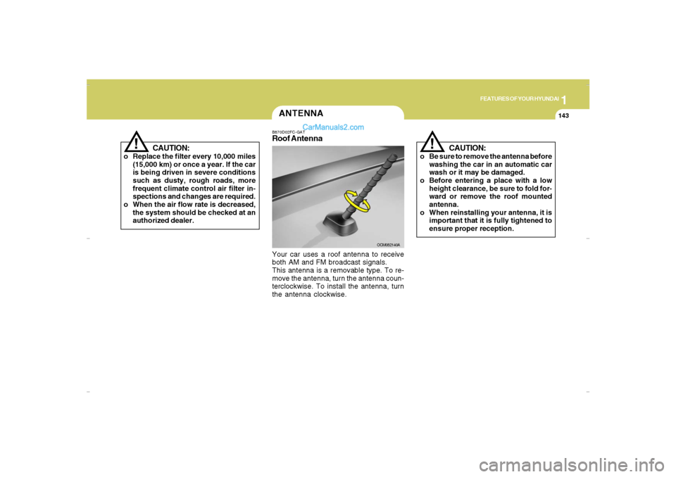
Roof AntennaYour car uses a roof antenna to receive
both AM and FM broadcast signals.
This antenna is a removable type. To re-
move the antenna, turn the antenna coun-
terclockwise. To install the antenna, turn
the antenna clockwise.
CAUTION:
o Replace the filter every 10,000 miles
(15,000 km) or once a year. If the car
is being driven in severe conditions
such as dusty, rough roads, more
frequent climate control air filter in-
spections and changes are required.
o When the air flow rate is decreased,
the system should be checked at an
authorized dealer.
!
Cmhma-1b.p653/20/2006, 5:00 PM 143
Page 226 of 355

2
DRIVING YOUR HYUNDAI
15
!
WARNING:
ABS (ESC) will not prevent accidents
due to improper or dangerous driving
maneuvers. Even though vehicle con-
trol is improved during emergency brak-
ing, always maintain a safe distance
between you and objects ahead. Vehicle
speeds should always be reduced dur-
ing extreme road conditions.
The braking distance for cars equipped
with an anti-lock braking system (Elec-
tronic Stability Control System) may be
longer than for those without it in the
following road conditions.
During these conditions the vehicle
should be driven at reduced speeds:
o Rough, gravel or snow-covered
roads.
o With tire chains installed.
o On roads where the road surface is
pitted or has different surface height.
The safety features of an ABS (ESC)
equipped vehicle should not be tested by
high speed driving or cornering. This
could endanger the safety of yourself or
others.
ANTI-LOCK BRAKE
SYSTEM (ABS)C120A01NF-AATThe Anti-Lock Brake System (ABS) is de-
signed to prevent wheel lock-up during
sudden braking or on hazardous road
surfaces. The ABS control module moni-
tors the wheel speed and controls the
pressure applied to each brake. Thus, in
emergency situations or on slick roads,
ABS will increase vehicle control during
braking.NOTE:o A click sound may be heard in the
engine compartment when the ve-
hicle begins to move after the engine
is started. These conditions are nor-
mal and indicate that the anti-lock
brake system (Electronic Stability
Control) is functioning properly.
o During ABS (ESC) operation, a pulsa-
tion may be felt in the brake pedal
when the brakes are applied. Also, a
noise may be heard in the engine
compartment while braking. These
conditions are normal and indicate
that the anti-lock brake system (Elec-
tronic Stability Control System) is
functioning properly.
ELECTRONIC STABILITY
CONTROL (ESC) SYSTEMC310A04JM-AAT(If installed)
!
WARNING:
Never drive too fast for the road condi-
tions or too quickly when cornering. Elec-
tronic stability control (ESC) will not pre-
vent accidents. Excessive speed in
turns, abrupt maneuvers and hydroplan-
ing on wet surfaces can still result in
serious accidents. Only a safe and at-
tentive driver can prevent accidents by
avoiding maneuvers that cause the ve-
hicle to lose traction. Even with ESC
installed, always follow all the normal
precautions for driving - including driv-
ing at safe speeds for the conditions.
Page 331 of 355

8
CONSUMER INFORMATION, REPORTING SAFETY DEFECTS & BINDING ARBITRATION OF WARRANTY CLAIMS6
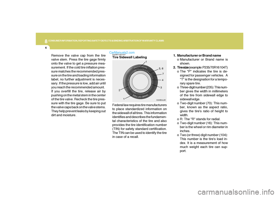
1. Manufacturer or Brand name
o Manufacturer or Brand name is
shown.
2. Tire size (example: P235/70R16 104T)
o The "P" indicates the tire is de-
signed for passenger vehicles. A
"T" is the designation for a tempo-
rary spare tire.
o Three-digit number (235): This num-
ber gives the width in millimeters
of the tire from sidewall edge to
sidewall edge.
o Two-digit number (70): This num-
ber, known as the aspect ratio,
gives the tire's ratio of height to
width.
o R: The "R" stands for radial.
o Two-digit number (16): This num-
ber is the wheel or rim diameter in
inches.
o Two (or three) digit number (104):
This number is the tire's load in-
dex. It is a measurement of how
much weight each tire can sup-
port.
Federal law requires tire manufacturers
to place standardized information on
the sidewall of all tires. This information
identifies and describes the fundamen-
tal characteristics of the tire and also
provides the tire identification number
(TIN) for safety standard certification.
The TIN can be used to identify the tire
in case of a recall.I030B01CM-AATTire Sidewall Labeling
I030B04JM
1
234 5, 6
7
1
Remove the valve cap from the tire
valve stem. Press the tire gage firmly
onto the valve to get a pressure mea-
surement. If the cold tire inflation pres-
sure matches the recommended pres-
sure on the tire and loading information
label, no further adjustment is neces-
sary. If the pressure is low, add air until
you reach the recommended amount.
If you overfill the tire, release air by
pushing on the metal stem in the center
of the tire valve. Recheck the tire pres-
sure with the tire gage. Be sure to put
the valve caps back on the valve stems.
They help prevent leaks by keeping out
dirt and moisture.
Page 333 of 355

8
CONSUMER INFORMATION, REPORTING SAFETY DEFECTS & BINDING ARBITRATION OF WARRANTY CLAIMS8
Intended Outboard Sidewall: The side
of an asymmetrical tire, that must al-
ways face outward when mounted on a
vehicle.
Kilopascal (kPa): The metric unit for
air pressure.
Load Index: An assigned number rang-
ing from 1 to 279 that corresponds to
the load carrying capacity of a tire.
Maximum Inflation Pressure: The
maximum air pressure to which a cold
tire may be inflated. The maximum air
pressure is molded onto the sidewall.
Maximum Load Rating: The load rat-
ing for a tire at the maximum permis-
sible inflation pressure for that tire.
Maximum Loaded Vehicle Weight:
The sum of curb weight; accessory
weight; vehicle capacity weight; and
production options weight.
Normal Occupant Weight: The num-
ber of occupants a vehicle is designed
to seat multiplied by 150 pounds (68
kg). Cold Tire Pressure: The amount of air
pressure in a tire, measured in pounds
per square inch (psi) or kilopascals
(kPa) before a tire has built up heat from
driving.
Curb Weight: This means the weight of
a motor vehicle with standard and op-
tional equipment including the maxi-
mum capacity of fuel, oil and coolant,
but without passengers and cargo.
DOT Markings: A code molded into the
sidewall of a tire signifying that the tire
is in compliance with the U.S. Depart-
ment of Transportation motor vehicle
safety standards. The DOT code in-
cludes the Tire Identification Number
(TIN), an alphanumeric designator which
can also identify the tire manufacturer,
production plant, brand and date of
production.
GVWR: Gross Vehicle Weight Rating
GAWR FRT: Gross Axle Weight Rating
for the front Axle.
GAWR RR: Gross Axle Weight Rating
for the rear axle.
I030D01JM-AATTire Terminology And Definitions
Air Pressure: The amount of air inside
the tire pressing outward on the tire. Air
pressure is expressed in pounds per
square inch (psi) or kilopascal (kPa).
Accessory Weight: This means the
combined weight of optional accesso-
ries. Some examples of optional ac-
cessories are, automatic transmission,
power seats, and air conditioning.
Aspect Ratio: The relationship of a
tire's height to its width.
Belt: A rubber coated layer of cords that
is located between the plies and the
tread. Cords may be made from steel or
other reinforcing materials.
Bead: The tire bead contains steel
wires wrapped by steel cords that hold
the tire onto the rim.
Bias Ply Tire: A pneumatic tire in which
the plies are laid at alternate angles
less than 90 degrees to the centerline of
the tread.
Page 345 of 355

9
VEHICLE SPECIFICATIONS2
J050A01CM-AATBRAKE
Dual hydraulic with brake booster
Ventilated disc
Disc type
Cable operated on rear wheel Type
Front brake type
Rear brake type
Parking brake
J040A01CM-AATELECTRICALItem
Battery
Generator2.7L Gasoline
3.3L Gasoline
CMF 68L
130A (13.5 V) 183.1 (4650)
184.1 (4675)
74.4 (1890)
67.9 (1725)
70.7 (1795)
106.3 (2700)
63.6 (1615)
63.8 (1620)
J010A01CM-AATDIMENSIONSOverall length
Overall width
Overall height
Wheel base
Wheel tread
in. (mm)
Standard
Option
Standard
with Roof Rack
Front
Rear
J060A01CM-AATFUEL SYSTEM
Engine
2.7L / 3.3LFuel tank capacity
19.8 us.gal (16.5 imp.gal, 75 liter)
J030A01CM-AATTIRE
Full
Temporary
Size Type
Inflation pressure kPa (psi)
235/70R16
235/60R18
T165/90R17NORMAL
LOADMAXIMUM
LOAD
220(32)
420(60) 210(30)
420(60)
Cmhma-9.p653/17/2006, 10:30 AM 2