Page 318 of 355

6
DO-IT-YOURSELF MAINTENANCE
32
FUSE PANEL DESCRIPTIONG200C01CM-AATEngine Compartment
OCM055023N
Note:Not all fuse panel descriptions in this manual may be applicable to your vehicle. It is accurate at the time of printing. When you
inspect the fuse box on your vehicle, refer to the fuse box label.
FUSE RATING
150A
10A
30A
40A
50A
40A
40A
20A
15A
40A
15A
20A
15A
40A
30A
15A
10ACIRCUIT PROTECTED
GENERATOR
A/CON RELAY
RR HTD RELAY
I/PJUNCTION BOX
I/PJUNCTION BOX
I/PJUNCTION BOX
ABS CONTROL MODULE, ESC CONTROL MODULE, MULTIPURPOSE CHECK
CONNECTOR
ABS CONTROL MODULE, ESC CONTROL MODULE, MULTIPURPOSE CHECK
CONNECTOR
DEICER RELAY
ENGINE CONTROL RELAY
HORN RELAY
IGNITION COIL #1~#6(GASOLINE), CONDENSOR(GASOLINE)
PURGE CONTROL SOLENOID VALVE(GASOLINE), VARIABLE INTAKE MANIFOLD
VALVE(GASOLINE), PCM(GASOLINE), OIL CONTROL VALVE(GASOLINE)
RAD FAN RELAY
CON FAN #1 RELAY, CON FAN #2 RELAY
MASS AIR FLOW SENSOR(GASOLINE), OXYGEN SENSOR #1~#4(GASOLINE),
PCM(GASOLINE)
IMMOBILIZER MODULE, INJECTOR #1~#6(GASOLINE), PCM(GASOLINE), A/
CON RELAY, FUEL PUMP RELAY
ALT
A/CON
RR HTD
BLR
BATT
P/WDW
ESC #1
ESC #2
DEICER
ECU MAIN
HORN
IG COIL
SENSOR #3
RAD FAN
CON FAN
SENSOR #2
SENSOR #1FUSE
Page 319 of 355

6
DO-IT-YOURSELF MAINTENANCE
33
FUSE RATING
15A
15A
15A
10A
10A
25A
20A
10A
40A
40A
50A
20A
15A
10A
10A
10A
10A
10A
10A
10A
10A
15A
20A
25A
30ACIRCUIT PROTECTED
FUEL PUMP RELAY
H/LP LO LH RELAY
H/LP LO RH RELAY
FR FOG RELAY
I/P JUNCTION BOX
FR WIPER RELAY, RAIN SNSR RELAY, FRONT WIPER MOTOR, MULTIFUNCTION SWITCH
H/LP HI RELAY
HEAD LAMP, INSTRUMENT CLUSTER
IGNITION SWITCH
IGNITION SWITCH, START RELAY
I/P JUNCTION BOX
ATM RELAY(GASOLINE), AWD ECM
PCM(GASOLINE)
GENERATOR
VEHICLE SPEED SENSOR, PCM(GASOLINE), SEMI ACTIVE CONTROL MODULE(GASOLINE)
CON FAN #1 RELAY, CON FAN #2 RELAY
INPUT SPEED SENSOR, OUTPUT SPEED SENSOR, TRANSAXLE RANGE SWITCH, BACK-UP LAMP SWITCH
ABS CONTROL MODULE, ESC CONTROL MODULE, YAW RATE SENSOR, AWD ECM, STOP LAMP SWITCH(GASOLINE), MULTIPURPOSE
CHECK CONNECTOR
REAR COMBINATION LAMP LH, POSITION LAMP LH
REAR COMBINATION LAMP RH, POSITION LAMP RH
GLOVE BOX CAMP, ICM RELAY BOX
-
-
-
-
-
FUEL PUMP
H/LP LO LH
H/LP LO RH
FR FOG
H/LP
FR WIPER
H/LP HI
H/LP HI IND
IGN #1
IGN #2
BATT
AT M
TCU
ALT DSL
ECU
COOLING
B/UP UP
ESC
TAIL LH
TAIL RH
SPARE
SPARE
SPARE
SPARE
SPAREFUSE
Page 323 of 355

7
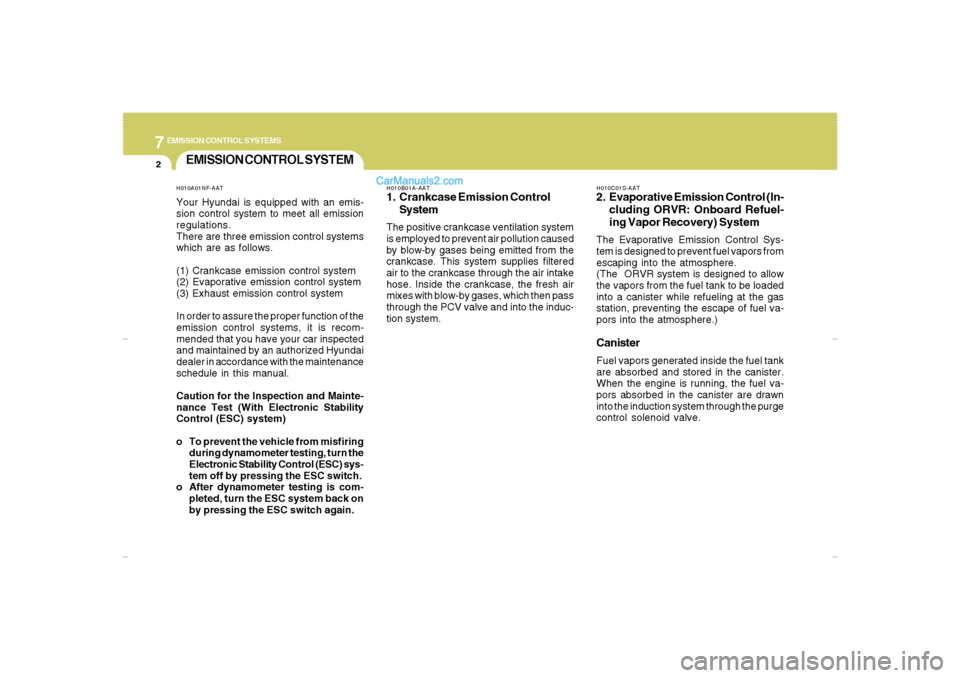
EMISSION CONTROL SYSTEMS2
EMISSION CONTROL SYSTEM
H010B01A-AAT1. Crankcase Emission Control
SystemThe positive crankcase ventilation system
is employed to prevent air pollution caused
by blow-by gases being emitted from the
crankcase. This system supplies filtered
air to the crankcase through the air intake
hose. Inside the crankcase, the fresh air
mixes with blow-by gases, which then pass
through the PCV valve and into the induc-
tion system.
H010A01NF-AATYour Hyundai is equipped with an emis-
sion control system to meet all emission
regulations.
There are three emission control systems
which are as follows.
(1) Crankcase emission control system
(2) Evaporative emission control system
(3) Exhaust emission control system
In order to assure the proper function of the
emission control systems, it is recom-
mended that you have your car inspected
and maintained by an authorized Hyundai
dealer in accordance with the maintenance
schedule in this manual.
Caution for the Inspection and Mainte-
nance Test (With Electronic Stability
Control (ESC) system)
o To prevent the vehicle from misfiring
during dynamometer testing, turn the
Electronic Stability Control (ESC) sys-
tem off by pressing the ESC switch.
o After dynamometer testing is com-
pleted, turn the ESC system back on
by pressing the ESC switch again.
H010C01S-AAT2. Evaporative Emission Control (In-
cluding ORVR: Onboard Refuel-
ing Vapor Recovery) SystemThe Evaporative Emission Control Sys-
tem is designed to prevent fuel vapors from
escaping into the atmosphere.
(The ORVR system is designed to allow
the vapors from the fuel tank to be loaded
into a canister while refueling at the gas
station, preventing the escape of fuel va-
pors into the atmosphere.)CanisterFuel vapors generated inside the fuel tank
are absorbed and stored in the canister.
When the engine is running, the fuel va-
pors absorbed in the canister are drawn
into the induction system through the purge
control solenoid valve.
Cmhma-7.p653/17/2006, 10:29 AM 2