Page 202 of 284

44IN CASE OF EMERGENCY
26
4. Check to see if the water pump drivebelt is missing. If it is not missing, check to see that it is tight. If the drive belt seems to be satisfactory, check for engine coolant leakingfrom the radiator, hoses or under the car. (If the air conditioning had been in use, it is normal for coldwater to be draining from it when you stop).
!WARNING:
While the engine is running, keep hair, hands, long hair and clothing away from moving parts such as the fan and drive belts to preventinjury.
!WARNING (Diesel only):
Never work on injection system with engine running or within 30 sec- onds after shutting off engine. High pressure pump, rail, injectors andhigh pressure pipes are subject to high pressure even after the engine stopped. The fuel jet produced byfuel leaks may cause serious in- jury, if it touch the body. People using pacemakers should not movethan 30cm closer to the ECU or wiring harness within the engine room while engine is running, sincethe high currents in the Common Rail system produce considerable magnetic fields.
5. If the water pump drive belt is broken or engine coolant is leaking out, stop the engine immediately and call the nearest Hyundai dealer for assis- tance.!WARNING:
Do not remove the radiator cap when the engine is hot. This can allow coolant to be blown out of the open- ing and cause serious burns.
6. If you cannot find the cause of the overheating, wait until the engine temperature has returned to nor-mal. Then, if the engine coolant has been lost, carefully add coolant to the reservoir (page 8-12) to bringthe fluid level in the reservoir up to the halfway mark.
7. Proceed with caution, keeping alert for further signs of overheating. Ifoverheating happens again, call a Hyundai dealer for assistance.
CAUTION:
Serious loss of engine coolant indi-cates there is a leak in the coolingsystem and this should be checked as soon as possible by a Hyundai dealer.
!
Page 205 of 284

4
CORROSION PREVENTION AND APPEARANCE CARE
29
4
IN CASE OF EMERGENCY
29
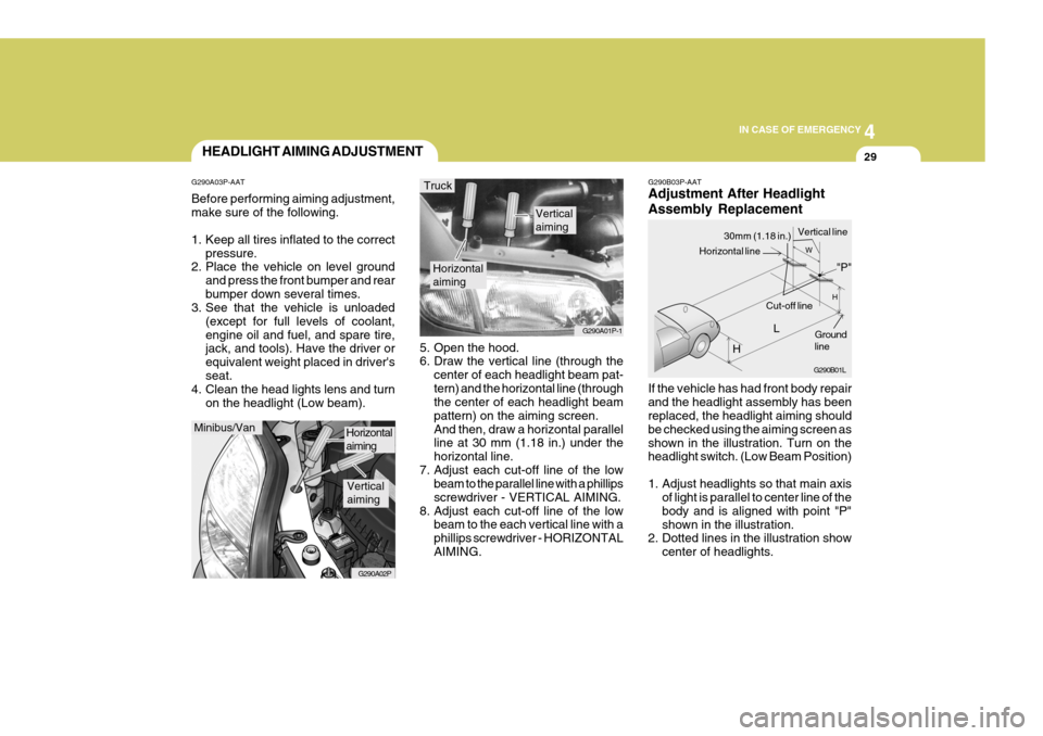
G290B03P-AAT Adjustment After Headlight Assembly Replacement If the vehicle has had front body repair and the headlight assembly has been replaced, the headlight aiming should be checked using the aiming screen asshown in the illustration. Turn on the headlight switch. (Low Beam Position)
1. Adjust headlights so that main axis
of light is parallel to center line of the body and is aligned with point "P"shown in the illustration.
2. Dotted lines in the illustration show
center of headlights.
5. Open the hood.
6. Draw the vertical line (through the
center of each headlight beam pat- tern) and the horizontal line (through the center of each headlight beam pattern) on the aiming screen.And then, draw a horizontal parallel line at 30 mm (1.18 in.) under the horizontal line.
7. Adjust each cut-off line of the low beam to the parallel line with a phillipsscrewdriver - VERTICAL AIMING.
8. Adjust each cut-off line of the low beam to the each vertical line with aphillips screwdriver - HORIZONTALAIMING.
Horizontal aiming
Verticalaiming
G290A01P-1
Truck
G290B01L
LW
H
H Cut-off line
Ground line
"P"
Horizontal line
30mm (1.18 in.) Vertical line
HEADLIGHT AIMING ADJUSTMENT
G290A03P-AAT Before performing aiming adjustment, make sure of the following.
1. Keep all tires inflated to the correct pressure.
2. Place the vehicle on level ground
and press the front bumper and rear bumper down several times.
3. See that the vehicle is unloaded
(except for full levels of coolant,engine oil and fuel, and spare tire, jack, and tools). Have the driver or equivalent weight placed in driver'sseat.
4. Clean the head lights lens and turn
on the headlight (Low beam).
Minibus/Van
G290A02P
Horizontal aiming
Verticalaiming
Page 207 of 284
4
CORROSION PREVENTION AND APPEARANCE CARE
31
4
IN CASE OF EMERGENCY
31
CAUTION:
Keep the lamps out of contact with petroleum products, such as oil,gasoline, etc.
!
4. Using a proper tool, remove the head- light assembly mounting bolts.
Replacement instructions:
1. Allow the bulb to cool. Wear eye protection.
2. Open the engine hood.
3. Always grasp the bulb by its plastic
base, avoid touching the glass. HSRFL270
G270A01P-GAT HEADLIGHT AND FRONT TURN SIGNAL LIGHT(Minibus/van)
Turn signal light
HSRFL271
Front position light
Headlight
HSRFL274
7. Push the bulb spring to remove the headlight bulb. HSRFL273
6. Turn the plastic cover counterclock- wise and remove it.
HSRFL272
5. Disconnect the power cord from the back of the headlight.
Page 216 of 284

44IN CASE OF EMERGENCY
40FUSE PANEL DESCRIPTION
G200B01P-GAT MINIBUS/VAN Engine Compartment (Diesel Engine)
G200A01P
NOTE: Not all fuse panel descriptions in this manual may be applicable to your vehicle. It is accurate at the time of printing. When you inspect the fuse box on your vehicle, refer to the fuse box label. AMPE-
RAGES
120A80A 30A30A30A40A30A 40A30A 30A 40A 50A
15A/20A
10A30A10A 10A 10A15A 10A 10A15A CIRCUIT PROTECTED
Generator
Glow relay, Glow control module (D4BB) ABS control module
Blower relay
Rear blower relay Fuse 16, 25, 26
Condenser fan main relay, Condenser fan relay (LOW)
Ignition switch, Generator, Start relay, COMP. Fuse, I/C FAN Fuse, ECU Fuse. ABS control module
Power window relay, Siren relay
Tail lamp relay, Head lamp relay
Front fog lamp relay, Hor n relay, Power connector
Inter cooler fan relay, Air temperature switch/Windshield glass defogger
A/C compressor relay
Main power relay (D4CB), Engine control relay, Fuel pump relay(Gasoline)
Illuminations, Left rear combination lamp, Left license lamp
Illuminations, Right rear combination lamp, Right license lamp
Left/Right horn
Front fog lamp switch, Left /Right front fog lampLeft head lamp
Right head lamp, Instrument cluster
Hazard relay, Fuse 23, 24
ALT
GLOW ABS
FR HTR
RR HTR DEF.
C/FAN
IGN
ABS P/W
TAIL
BATT
I/C FAN/FR HTD COMP.
ECU
T/LP(LH) T/LP(LH) HORN
FOG
H/LP(LH)
H/LP(RH)
FUSIBLE
LINK
FUSE
DESCRIPTION
POWER CONNECTOR
Page 217 of 284

4
CORROSION PREVENTION AND APPEARANCE CARE
41
4
IN CASE OF EMERGENCY
41
G200C01P-GAT (Gasoline Engine)
G200B01PAMPE-
RAGES
120A30A 30A30A40A30A 40A30A 30A 40A 50A
15A/20A
10A30A10A 10A 10A15A 10A 10A15A CIRCUIT PROTECTED
GeneratorABS control module
Blower relay
Rear blower relayFuse 16, 25, 26
Condenser fan main relay, Condenser fan relay (LOW)
Ignition switch, Generator, Start relay, COMP. Fuse,FR HTD Fuse,ECU Fuse. ABS control module
Power window relay, Siren relay
Tail lamp relay, Head lamp relay
Front fog lamp relay, Horn relay, Power connector
Inter cooler fan relay, Air temperature switch/Windshield glass defogger
A/C compressor relay
Main power relay (D4CB), Engine control relay, Fuel pump relay(Gasoline)
Illuminations, Left rear combination lamp, Left license lamp
Illuminations, Right rear combination lamp, Right license lamp
Left/Right horn
Front fog lamp switch, Left /Right front fog lamp Left head lamp
Right head lamp, Instrument cluster
Hazard relay, Fuse 23, 24
ALT
ABS
FR HTR
RR HTR
DEF.
C/FAN
IGN
ABS P/W
TAIL
BATT
I/C FAN/FR HTD
COMP.ECU
T/LP(LH) T/LP(LH) HORNFOG
H/LP(LH)
H/LP(RH)
FUSIBLE
LINK
FUSE
DESCRIPTION
POWER CONNECTOR
Page 220 of 284
44IN CASE OF EMERGENCY
44
G200E01P-GAT TRUCK Engine Compartment
G200E01P
NOTE: Not all fuse panel descriptions in this manual may be applicable to your vehicle. It is accurate at the time of printing. When you inspect the fuse box on your vehicle, refer to the fuse box label. AMPE-
RAGES
10080 303050404030 303030 10 1015 10 1010 15 1010 20 CIRCUIT PROTECTED
Generator
Glow control
Blower control
Power window control
Fog lamp, Horn, Power connector, Fuse 13, 14, 15
Ignition switch, Star t relay, Generator
Tail lamp relay, Head lamp fuse
TCI fuse, Compressor fuse
Condenser fan ABS control moduleABS control module
Idle up fan motor relay
A/C compressor relay
Engine control relay
Left tail lamp, Illumination
Right tail lamp, Illumination
Horn
Fog lamp Left head lamp Right head lampFuse 23, 24
LABEL ALT
GLOW
HTR
P/WINDOW
BATT
IGN
TAIL A/C
C/FAN ABS.1
ABS.2
TCI
COMP ECU
TAIL (LH)
TAIL (RH)
HORN
FOG
H/LP (LH)
H/LP (RH)DESCRIP- TION
FUSIBLE LINK
FUSE
POWER CONNECTOR
Page 221 of 284

4
CORROSION PREVENTION AND APPEARANCE CARE
45
4
IN CASE OF EMERGENCY
45
G200F01P-GAT Passenger Compartment
G200F01P CIRCUIT PROTECTED
Power outside mirror switch, Cigarette lighter, Digital clock
Audio
DRL, ABS control module, condenser fan relay
Wiper motor, Washer motor
Blower relay, Head lamp relay, Power window relay, Defogger relay, Mode actuator,
Rear fog relay, Head lamp leveling switch, Heater control panel, Left (Right) head
lamp leveling actuator
ECM, Neutral switch, Injection pump, Engine control relay, Intercooler fan relay, EGR
solenoid valve, SRS control module SRS control module
Back-up lamp switch, Vehicle speed sensor, ABS relay, Instrument cluster,
Pre-excitation resistor
Hazard switch
TA C M
Instrument cluster
A/C switch
Stop lamp switch
Hazard switch Not used. Not used.Not used.
Defogger relay
Rear fog lamp relay
Left power door lock actuator Not used.
ECM, Star t relay
Digital clock, Tachograph, Power antenna, Audio
Instrument cluster, Front (Rear) room lamp, TACM, Door warning switch & Key ill.
AMPERAGES 15A 10A10A 20A 10A 10A 15A10A10A 10A10A 10A 10A10A---
10A10A15A -
10A10A 10A
FUSE
123 4 5 6 7 8 9
10 1112 13 14 1516 17 1819 20 2122 23 24
Page 222 of 284
Washing/Waxing/Polishing ........................................... 5-2
Window Glass .............................................................. 5-3
Chassis and Underbody Protection .............................. 5-3
Engine Compartment .................................................... 5-4Tire............................................................................... 5-5
5
APPEARANCE CARE
5